
Related Manuals for Dakota NDT CMX1


Summary of Contents for Dakota NDT CMX1
- Page 1 OPERATION MANUAL Dakota NDT Material & Coating Thickness Gauge P/N P-170-0006 Rev 1.00, January 2024...
-
Page 3: Table Of Contents
CONTENTS CHAPTER ONE INTRODUCTION ..............1 1.1 D ......................... 1 ISCLAIMER CHAPTER TWO QUICK STARTUP GUIDE ............2 2.1 CMX1 O ........................ 2 VERVIEW 2.2 A ....................4 ROBE ECOGNITION 2.3 S ..................5 ELECTING THE RANSDUCER 2.4 P & C .................... - Page 4 9.5 I (CT) ............... 76 NTRODUCTION TO OATING EASUREMENT 9.6 T (CT) ................77 OINT OATING ALIBRATION CHAPTER TEN ADDITIONAL FEATURES OF THE CMX1 ......82 10.1 H ......................82 PEED 10.2 A ........................83 LARM 10.3 D ......................85 IFFERENTIAL 10.4 K...
- Page 5 12.1 C ................104 OMPUTER YSTEM EQUIREMENTS 12.2 I ..................... 104 NSTALLING 12.3 C CMX1 .................. 104 OMMUNICATING WITH THE 12.4 L ........................104 OWER 12.5 U CMX1 ....................104 PGRADING THE APPENDIX A - VELOCITY TABLE ..............106 APPENDIX B - SETUP LIBRARY ..............108 ...
-
Page 7: Chapter One Introduction
CHAPTER ONE INTRODUCTION The Dakota NDT model CMX1 is an ultrasonic thickness gauge that measures with extreme versatility. It has the ability to simultaneously measure coatings and material thicknesses while maintaining the ability to still locate pits, flaws and defects in the material. -
Page 8: Chapter Two Quick Startup Guide
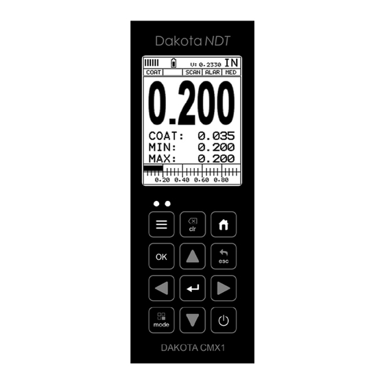
CHAPTER TWO QUICK STARTUP GUIDE Turn the CMX1 on and off using the switch located on the bottom right corner of the keypad. When CMX1 is initially turned on, a flash logo and blinking lights will be displayed, followed by attempting to identify the transducer(probe) currently plugged into the gauge. - Page 9 CMX1 Material & Coating Thickness Gauge B. Battery Icon – Indicates the amount of battery life the CMX1 has remaining. C. Velocity – The material velocity value the CMX1 is currently using or calibrated for. Displayed in both English or Metric units, depending on the what units the gauge is set for.
-
Page 10: Auto Probe Recognition
Dakota NDT 2.2 Auto Probe Recognition When the CMX1 is initially powered up, the gauge will automatically check to see if the transducer plugged into the gauge can be recognized. The steps that follow assume the CMX1 recognized the probe type:... -
Page 11: Selecting The Transducer Type
& Calibration section outlined below. 2.3 Selecting the Transducer Type If the CMX1 does not identify a specific transducer type on initial power up, the user will be required to select a type from a predefined list of types by diameter and frequency. - Page 12 Dakota NDT Selecting the Transducer Type 1) Press the keys to display the factory list of transducer types (by diameter and frequency). 2) Press the arrow keys to scroll through the transducer list until the appropriate type is highlighted.
-
Page 13: Probe Zero & Calibration
2.4 Probe Zero & Calibration The next steps are to perform a probe zero and calibrate the CMX1 to the material and transducer being used. If the sound velocity is unknown, the CMX1 can be calibrated to a known thickness sample. - Page 14 Coating Probe Identified Coating Probe Not Identified 3) The screens illustrated above will be briefly displayed followed by the main measurement screen. The CMX1 is ready to be calibrated.
- Page 15 CMX1 Material & Coating Thickness Gauge Performing a Manual Probe Zero (On Block) Note: When the zero probe option is set to manual, the probe zero disk (battery cap) located on the top of the gauge, will be used as a zero standard and the warning screen illustrated above will be displayed.
- Page 16 Note: The value that is displayed will change depending on the current velocity setting in the CMX1. Disregard the number that is displayed. It is not important. What is important is accurately performing the steps outlined above to insure reliability of the probe zero calculation.
- Page 17 CMX1 Material & Coating Thickness Gauge Using a Known Thickness Note: Be sure that the probe zero procedure has been performed prior to performing this calibration procedure. 1) Physically measure an exact sample of the material or a location directly on the material to be measured using a set of calipers or a digital micrometer.
-
Page 18: Zero Coating
If the thickness is not correct, repeat the steps above. 2.5 Zero Coating In order to account for very slight electronic differences in transducers of the same type, frequency, and diameter, the CMX1 has been equipped with a “zero coating” feature. This enables the CMX1... - Page 19 CMX1 Material & Coating Thickness Gauge eliminating potential errors incurred from slight differences in the manufacturing processes. The procedure is outlined below: Performing a Coating Zero 1) Press the key once to activate the measurement mode options. 2) Use the arrow keys to scroll through the sub menu items until Coating Only (CT) mode is highlighted.
-
Page 20: Coating Calibration
If the velocity of the coating is known, and different than the above default setting, the user can simply enter the coating velocity into the CMX1. However, if the velocity is unknown, the CMX1 can also be calibrated to a specific... - Page 21 If the coating velocity is known, the user may wish to simply enter the velocity number into the CMX1, rather than have the CMX1 calculate the velocity value using a known thickness on a coating sample. The steps for entering the velocity are...
- Page 22 It would be very handy to carry a set of mechanical calipers to use in conjunction with the CMX1 for calibration in the field: Using a Coating Sample to Calibrate 1) Physically measure a location on a coating sample using a set of calipers or a digital micrometer.
- Page 23 CMX1 Material & Coating Thickness Gauge Note: In PECT (pulse-echo coating) mode, the coating sample must be coupled to metal in order to calibrate successfully. Simply place a drop of couplant on a piece of metal, lay the coating sample over the couplant on the metal and proceed to step 2.
-
Page 24: Measure
If the thickness is not correct, repeat the steps above. 2.7 Measure The CMX1 is now ready to measure. There are two different measurement view options, each with a specific purpose – Digits & B-Scan. The steps below outline how to toggle between the different view mode options:... - Page 25 DIGITS: Displays the digital thickness value using a large font size. This view is useful when the CMX1 is being used as a basic thickness gauge. BSCAN: The Time Based B-Scan provides the user with a cross sectional view of the material being tested.
- Page 26 Dakota NDT 1) Press the key once to activate the menu items tab. Press the key multiple times to tab right and the key multiple times to tab left until the DISP menu is highlighted and displaying the submenu items.
- Page 27 CMX1 Material & Coating Thickness Gauge 1) Use the arrow keys to scroll through the sub menu items until B-START or B-DEPTH is highlighted. 2) Press the key to display the digits edit box. 3) Press the arrow keys to scroll the highlighted value.
- Page 28 65 measurements a second in scan mode. When the CMX1 is idle, only the left vertical bar will be displayed. However, when the CMX1 is making a measurement, four or five of the bars should be displayed on the repeatability indicator.
-
Page 29: Chapter Three Keyboard, Menu, & Connector Reference
CHAPTER THREE KEYBOARD, MENU, & CONNECTOR REFERENCE 3.1 Menu Key (Operation & Sub Menus) The Menu key activates the primary menu structure containing 8 menu tab groups. These tab groups then contain sub menu items, or functions. The sub menu items have been organized in tab groups according to how closely they are related to the individual tab group names. - Page 30 Dakota NDT Activating and Getting Around in the Menu Items 1) Press the key once to activate the menu items tab. Press the key multiple times to tab right, and the key multiple times to tab left until the desired tab group is highlighted and displaying the submenu items.
-
Page 31: Probe - Menu
If the CMX1 is not zeroed correctly, all of the measurements made using the CMX1 may be in error by some fixed value. The CMX1 is equipped with an optional automatic or manual zero feature. Refer to the section on page 41, for an explanation of this important procedure. -
Page 32: Disp (Display) - Menu
Refer to page 77 for further info. COATING VEL: Function to calibrate the CMX1 to a specific coating material type by entering a coating velocity. Refer to page 15 or 73 for further info. -
Page 33: Setup - Menu
Refer to page 100 for further info. DEFAULT SETUP: Loads a basic default setup. Use only as a last resort when the setups in the CMX1 have been corrupted and a computer is not accessible. Refer to page 101 for further info. -
Page 34: Xfer (Transfer) - Menu
CMX1. Refer to page 88 for further info. SHOW DATE: Gives the user the ability to display the date and time in the waveform area of the CMX1. The options are OFF, DATE, TIME, BOTH. Refer to page 89 for further info. -
Page 35: Esc Key
The modes can be all or a combination of the entire set of modes the CMX1 offers, depending on which transducer is being used as follows: Coating Off (P-E), Coating On (PECT), Temp Comp (PETP), Thru-Coat (E-E), Thru Coat Verify (E-EV), and Coating Only (CT). - Page 36 C female connector. It is designed to connect directly from the CMX1 to a standard USB type A port on a PC. The cable supplied with the CMX1 is a USB type C to a USB type A (pt# N-003-0330).
-
Page 37: Chapter Four Principals Of Ultrasonic Measurement
CHAPTER FOUR PRINCIPALS OF ULTRASONIC MEASUREMENT 4.1 Time versus thickness relationship Ultrasonic thickness measurements depend on measuring the length of time it takes for sound to travel through the material being tested. The ratio of the thickness versus the time is known as the sound velocity. In order to make accurate measurements, a sound velocity must be determined and entered into the instrument. -
Page 38: Temperature
CMX1, and a key is pressed to establish a zero point for the particular transducer. If the Auto Zero feature is enabled, a simple key press will perform an electronic zero to establish the same zero point. - Page 39 CMX1 Material & Coating Thickness Gauge barrier. This allows the transducer the ability to achieve very high sensitivity for detecting small defects. Also, the surface of the test material does not have to be as flat in order to obtain good measurements.
- Page 40 Dakota NDT is that a comparison is made, between the 2 and 3 echoes, to verify that a peak jump has not occurred, providing an additional level of confidence to the measurement. The disadvantage is that 3 reflections are needed which requires the use of gates with controllable thresholds to adjust for sensitivity over a given measurement range.
-
Page 41: Chapter Five Selecting The Measurement Mode
SELECTING THE MEASUREMENT MODE 5.1 The setup library The CMX1 contains 64 user configurable preset locations to store custom setups for easy recall. These setups can be optimized for the user’s specific application needs and can also be stored on a PC and transferred bi-directionally using Dakota’s PC interface software included with the instrument. - Page 42 This mode can also be used as a stand alone coating thickness gauge, where the coating has not been applied to another material surface. An auto identified coating probe must be attached to the CMX1 in order to enable this mode.
-
Page 43: Factory Setup Chart
CMX1 Material & Coating Thickness Gauge 5.3 Factory Setup Chart Name Comment 1 Gn/AGC Velocity Enter Custom Name … … … … … … …... -
Page 44: Chapter Six Making Measurements
In this case the reference disk mounted to the CMX1 is not used. This is called two- point calibration and is described on page 49. - Page 45 CMX1 Material & Coating Thickness Gauge Note: If the transducer is not identified on power up, be sure the transducer type selected is the same as the transducer plugged into the CMX1. Failure to do this will result in erroneous measurements:...
- Page 46 Dakota NDT 3) Press the arrow keys to toggle the coating option on/off. 4) Wipe all couplant from the transducer face and proceed to the Probe Zero section that follows. In this second example the transducer was not identified and will force the user to...
-
Page 47: Probe Zero
The next step is to perform a probe zero. The zero function is a very important and necessary function that must be done prior to calibration. It should be done on a regular basis. In fact, the CMX1 has been programmed to force this issue at regular... - Page 48 However, when the manual zero is being used, the CMX1 must be in pulse-echo mode in order to perform the zero. The CMX1 will also see to it that this occurs by simply forcing the gauge into this mode when zero. Therefore, if the CMX1 is in the echo-echo measurement mode and a manual zero is being performed, the CMX1 will put the gauge into pulse-echo mode automatically before performing the zero.
- Page 49 Coating Probe Not Identified 3) The screens illustrated above will be briefly displayed followed by the main measurement screen. The CMX1 is ready to be calibrated. Performing a Manual Probe Zero (On Block) Note: When the zero probe option is set to manual, the probe zero disk (battery cap) located on the top of the gauge will be used as a zero standard and the warning screen illustrated above will be displayed.
- Page 50 Dakota NDT 1) Press the keys to enter the main measurement screen and begin the manual zero process. 2) Apply a drop of couplant on the transducer and place the transducer in steady contact with the probe zero disk and obtain a steady reading.
-
Page 51: Material Calibration
6.3 Material Calibration In order for the CMX1 to make accurate measurements, it must be set to the correct sound velocity of the material being measured. Different types of materials have different inherent sound velocities. For example, the velocity of sound through steel is about 0.233 inches per microsecond, versus that of aluminum, which is about... - Page 52 Dakota NDT 1) Press the key once to activate the menu items tab. Press the key multiple times to tab right and the key multiple times to tab left until the CAL menu is highlighted and displaying the submenu items.
- Page 53 As previously discussed, the CMX1 has a one or two point calibration option. The one point calibration option is most suited for linearity over large ranges, as noted above.
- Page 54 Dakota NDT 1) Physically measure an exact sample of the material or a location directly on the material to be measured using a set of calipers or a digital micrometer. 2) Apply a drop of couplant on the transducer and place the transducer in steady contact with the sample or actual test material.
- Page 55 (6.35mm), the user would perform a one point calibration on a known thickness sample close to .250” (6.35mm), followed by a two point calibration close to .080” (2.03mm). When a two point calibration is performed, the CMX1 calculates the zero and the velocity. The following steps outline this procedure:...
- Page 56 Dakota NDT 2) Apply a drop of couplant on the transducer and place the transducer in steady contact with the sample or actual test material. Be sure that the reading is stable and the repeatability indicator, in the top left corner of the display, is fully lit and stable.
- Page 57 CMX1 Material & Coating Thickness Gauge 9) Finally, press the key to return to the measurement screen and begin taking readings. Note: CHECK YOUR CALIBRATION! Place the transducer back on the calibration point. The thickness reading should now match the known thickness.
- Page 58 Dakota NDT 2) Use the arrow keys to scroll through the sub menu items until MAT is highlighted. 3) Press the key to display the list of material types. 4) Press the arrow keys to scroll through the material list until the appropriate material is highlighted.
- Page 59 CMX1 Material & Coating Thickness Gauge To calibrate the CMX1 for a specific type of coating using samples with known thicknesses, please refer to the chapter 9 – Pulse-Echo Coating (PECT) or Coating (CT) for a complete explanation of using the CMX1 for coating...
-
Page 60: Chapter Seven Using The Digits & B-Scan Displays
CMX1. We’ll take a better look at these options in this chapter. Note: In order to recall and use the new adjustments made to the CMX1 at a later time, the user must save the modified settings in one of the setup locations. Refer page 94 for more information on setups. - Page 61 When all the vertical bars are fully illuminated and the last digit on the digital thickness value is stable, the CMX1 is reliably measuring the same value 3 to 200 times per second, depending on which measurement mode and features are enabled.
- Page 62 When all the vertical bars are fully illuminated and the last digit on the digital thickness value is stable, the CMX1 is reliably measuring the same value 3 to 200 times per second, depending on which measurement mode and features are enabled.
- Page 63 CMX1 Material & Coating Thickness Gauge High Speed Scan Mode (ON/OFF) Alarm Mode (ON/OFF/AUDIBLE) Gain Setting (VLOW, LOW, MED, HI, VHI) E. Digital Material Thickness Value – Smaller font size when the B-Scan display view is enabled.
-
Page 64: Activating B-Scan View
Dakota NDT 7.2 Activating B-Scan View To use the B-Scan feature it must be enabled in the display menu. The following steps will help you do just that: Enabling the B-Scan Feature 1) Press the key once to activate the menu items tab. Press the... -
Page 65: Adjusting The B-Scan Start (B-Start) & Depth (B-Depth)
CMX1 Material & Coating Thickness Gauge 7.3 Adjusting the B-Scan Start (B-START) & Depth (B-DEPTH) In order to use the B-Scan and Scan Bar features of the CMX1 effectively, the starting depth and overall depth must be setup correctly. This can be adjusted using the B-START and the B-DEPTH features of the CMX1. - Page 66 Dakota NDT Adjusting the Starting Depth (B-START) 1) Press the key once to activate the menu items tab. Press the key multiple times to tab right, and the key multiple times to tab left, until the DISP menu is highlighted and displaying the submenu items.
- Page 67 CMX1 Material & Coating Thickness Gauge 5) Press the arrow keys to scroll the highlighted value. 6) Press the arrow keys to scroll the digit locations. 7) Repeat steps 5 & 6 until the B-Start value is correctly displayed. 8) Press the key to set the B-Start value and return to the menu screen, to cancel entering the B-Start.
- Page 68 Dakota NDT 2) Use the arrow keys to scroll through the sub menu items until B-DEPTH is highlighted. 3) Press the arrow keys to scroll the value. When the correct width is being displayed, proceed to step 8. 4) Alternatively, press the key to display the Digits Edit Box.
- Page 69 CMX1 Material & Coating Thickness Gauge The CMX1 has the capability to adjust the the scrolling speed of the time based B- Scan displayed in the gauge. The procedures to adjust the speed are outlined below: Adjusting the B-Scan Speed 1) Press the key once to activate the menu items tab.
-
Page 70: Gain
7.4 Gain The gain, or amplification of the return echoes, can be adjusted in the CMX1 to accommodate a variety of applications. The setting of the gain is crucial in order to obtain valid readings during the measurement process. Too much gain may result in erroneous measurements, by detecting on noise rather than the actual material back wall itself. - Page 71 CMX1 Material & Coating Thickness Gauge Note: When the echo-echo thru-paint measurement mode is selected, the manual gain feature is disabled and grayed out in the menu items. In this mode, the CMX1 switches to an automatic gain mode (AGC) that optimizes the gain setting automatically in the hardware of the CMX1.
-
Page 72: Chapter Eight Thru Paint Measurement Technique
The CMX1 can also be configured for thru paint applications by selecting a factory setup stored in the list of setups in the CMX1. Refer to page 94 for information on recalling a setup. Once either the transducer type or setup has been selected, the... -
Page 73: Chapter Nine Pulse-Echo Coating & Coating Techniques
The CMX1 is preset to a coating velocity of 0.0850 in/µsec (2159 m/sec) from the factory. This velocity is a very close approximation of the common coating velocities found in the field. - Page 74 Dakota NDT 3) From the tabbed menus under TUNE, MEASURE MODE. The steps that follow will demonstrate all three methods in the order listed above: Probe Automatically Recognized (PECT only) 1) Press the key once to use the identified probe, or to display a list of optional transducers.
- Page 75 CMX1 Material & Coating Thickness Gauge 3) Press the arrow keys to toggle the coating option on/off. Multi Mode Key Pressed (PECT & CT) Applied to Metals Not Applied to Metals 1) Press the key located on bottom left of the keypad to display the MEASURE MODE options menu.
- Page 76 Dakota NDT 3) Press the key to enable the coating option, or to cancel changing the measure mode, and return to the main measurement screen. Measure Mode (Tabbed Menus) – (PECT & CT) Applied to Metals Not Applied to Metals 1) Press the key once to activate the menu items tab.
-
Page 77: Zero Coating
CMX1 Material & Coating Thickness Gauge 9.3 Zero Coating In order to account for very slight electronic differences in transducers of the same type, frequency, and diameter, the CMX1 has been equipped with a “zero coating” feature. This enables the CMX1... - Page 78 Dakota NDT 5) Press the key once to activate the menu items tab. Press the key multiple times to tab right and the key multiple times to tab left until the PRB menu is highlighted and displaying the submenu items.
-
Page 79: Coating Calibration (Pect)
If the coating velocity is known, the user may wish to simply enter the velocity number into the CMX1, rather than have the CMX1 calculate the velocity value using a known thickness on a coating sample(s). The steps for entering the velocity are... - Page 80 As previously discussed, the CMX1 offers a one point calibration option for coating in PECT measurement mode. It is also import to reiterate that the coating sample must be coupled to a metallic material in order to perform the calibration.
- Page 81 CMX1 Material & Coating Thickness Gauge Note: It’s always handy to carry a set of mechanical calipers to use in conjunction with the CMX1 for calibration in the field: One Point Calibration Note: Be sure that the probe zero procedure has been performed prior to performing this calibration procedure.
-
Page 82: Introduction To Coating Measurement (Ct)
Dakota NDT 3) Use the arrow keys to scroll through the sub menu items until COATING 1PT is highlighted. 4) Press the key to display the Digits Edit Box. 5) Press the arrow keys to scroll the highlighted value. 6) Press the arrow keys to scroll the digit locations. -
Page 83: Two Point Coating Calibration (Ct)
In the previous sections we’ve discussed how to setup and use the coating feature for use in conjunction with material thickness and flaw and pit detection. The CMX1 also has the capability to be used for general coating measurements. This measurement mode is called Coating (CT) and can be enabled using the same methods as described in a previous section above. - Page 84 Dakota NDT 1) Physically measure the thicker of the two samples of coating, as close as possible to the maximum expected coating measurement range, using a set of calipers or a digital micrometer. Very Important: If coating measurements will be made with the coating applied to a metal surface, the calibration must be done in the same manner, with the samples coupled to a metal surface.
- Page 85 CMX1 Material & Coating Thickness Gauge 4) Press the key to display the Digits Edit Box. 5) Press the arrow keys to scroll the highlighted value. 6) Press the arrow keys to scroll the digit locations. 7) Repeat steps 5 & 6 until the known thickness value is correctly displayed.
- Page 86 Dakota NDT Very Important: If coating measurements will be made with the coating applied to a metal surface, the calibration must be done in the same manner, with the samples coupled to a metal surface. However, if the coating will be measured as a stand alone material, the calibration must be performed the same way.
- Page 87 CMX1 Material & Coating Thickness Gauge 6) Press the arrow keys to scroll the digit locations. 7) Repeat steps 5 & 6 until the known thickness value is correctly displayed. 8) Press the key to calculate the velocity and return to the menu screen, to cancel the coating one point calibration.
-
Page 88: Chapter Ten Additional Features Of The Cmx1
ADDITIONAL FEATURES OF THE CMX1 10.1 High Speed Scan The High Speed Scan feature of the CMX1 increases the overall repetition rate to a maximum of 140Hz with a high speed screen refresh rate of 25 times a second. This... -
Page 89: Alarm Mode
There are two limits, or alarm values, that can be setup in the CMX1 – ALARM LOW and ALARM HIGH limits. However, the user may choose to activate and utilize only one of the limit values, depending on their specific application requirements. - Page 90 Dakota NDT Setting the Alarm Low Limit 1) Assuming the ALARM is ON, use the arrow keys to scroll through the sub menu items until ALARM LOW is highlighted. 2) Press the arrow keys to scroll the value. When the correct alarm value is being displayed, proceed to step 7.
-
Page 91: Differential Mode
ALARM HIGH limit. 10.3 Differential Mode The Differential Mode of the CMX1 provides the user with the ability to set a nominal value, according to what the expected thickness should be, and measure the +/- difference from the nominal value entered. This feature is typically used in QA incoming inspections on pipes, plate stock, coils, etc. - Page 92 Dakota NDT 3) Use the arrow keys to toggle the DIFFERENTIAL on. A value will appear to the right of DIFFERENTIAL. 4) Continue on to the next section “Setting the Differential Value”. Setting the Differential Value 1) Assuming DIFFERENTIAL has been enabled and a value is being displayed...
-
Page 93: Key Click
10.4 Key Click When a key is pressed on the CMX1 keypad, the user can control whether or not an audible beep is sounded and at what volume level, if any. The procedure for this feature/preference is outlined below:... -
Page 94: Set Date
Dakota NDT 10.5 Set Date The CMX1 is equipped with an internal clock to time and date stamp the log, setup and screen capture files for reporting/documentation purposes. The procedures for setting the time and date are outlined below: Setting Date & Time 1) Press the key once to activate the menu items tab. -
Page 95: Show Date & Time
CMX1 Material & Coating Thickness Gauge 4) Press the , & arrow keys to scroll the field locations. 5) Press the arrow keys multiple times to scroll the value. 6) Repeat steps 4 & 5 until the Time & Date is correctly displayed. -
Page 96: Freeze & Capture
.tif (tagged image) file format that can be opened using any graphics viewer. With the storage capacity of the CMX1 the user can store as many screens shots as needed. It should also be mentioned that this feature is immediately activated on boot up. -
Page 97: Capture Viewer
The capture viewer enables a user to view any of the saved screen captures on the SD card, using the CMX1. This is handy if a PC isn’t available, but the user has a need to review the screen shots captured. - Page 98 Dakota NDT Using the Viewer 1) Press the key once to activate the menu items tab. Press the key multiple times to tab right and the key multiple times to tab left until the XFER menu is highlighted and displaying the submenu items.
- Page 99 CMX1 Material & Coating Thickness Gauge 5) Press the key to display the image. 6) Press the key to return to the measurement screen.
-
Page 100: Chapter Eleven Setups - Create, Store, Edit, & Recall
11.2 Opening a Setup The CMX1 is loaded with a number of setups from the factory. These setups can be opened, edited, and saved to any one of 64 setup locations. If a factory setup is written over, the user can simply reload the default factory setups at anytime using the utility software included with the CMX1. - Page 101 CMX1 Material & Coating Thickness Gauge Opening a Setup 1) Press the key once to activate the menu items tab. Press the key multiple times to tab right and the key multiple times to tab left until the SETUP menu is highlighted and displaying the submenu items.
-
Page 102: Saving A Setup
11.3 Saving a Setup Once the CMX1 parameters and features have be adjusted for an application, the user may elect to save these setting to a specific setup location for future use. This can potentially save time and reduce error between users. - Page 103 CMX1 Material & Coating Thickness Gauge Saving a Setup 1) Press the key once to activate the menu items tab. Press the key multiple times to tab right and the key multiple times to tab left until the SETUP menu is highlighted and displaying the submenu items.
- Page 104 Dakota NDT 5) When the parameter to edit is highlighted, press the key to activate the Alpha Edit Box. 6) Use the , and arrow keys to scroll through the characters, the key to select characters, and the key to backspace through the characters, until the Name or Note fields have been edited.
- Page 105 CMX1 Material & Coating Thickness Gauge 10) Press the key to activate the Setup List Box. 11) Use the arrow keys to scroll through the setups until the target location to save the Setup is highlighted. 12) Press the key to activate the confirmation screen.
-
Page 106: Deleting A Saved Setup
Dakota NDT 11.4 Deleting a Saved Setup This option allows a user to delete setup files that were previously saved and no longer needed. It’s a simple feature to allow the user to do a bit of “house cleaning”. Deleting a Setup 1) Press the key once to activate the menu items tab. -
Page 107: Using The Default Setup
11.5 Using the Default Setup The default setup feature was added to the CMX1 to use, as a last resort, if there are no setups stored in the gauge –factory or otherwise. The only time this might... - Page 108 Dakota NDT Using the Default Setup 1) Press the key once to activate the menu items tab. Press the key multiple times to tab right and the key multiple times to tab left until the SETUP menu is highlighted and displaying the submenu items.
-
Page 109: Selecting A Language
CMX1 Material & Coating Thickness Gauge 11.6 Selecting a Language The CMX1 is equipped with a language option. Currently, the only languages supported are English, Spanish, German, French, Hungarian, Czech, however the list continues to grow. The steps to select one of these languages are outlined as... -
Page 110: Chapter Twelve Using The Utility Software
12.5 Upgrading the CMX1 The CMX1 can be upgraded to the latest revision of firmware at any time. Simply download the latest version posted on the Dakota NDT website, copy the upgrade file... - Page 111 CMX1 Material & Coating Thickness Gauge to the main drive directory CMX1, and use the upgrade utility located in the XFER menu. The process is very easy and convenient, allowing our users to stay current with updated feature additions and bug fixes. The procedure to upgrade your CMX1...
-
Page 112: Appendix A - Velocity Table
APPENDIX A - VELOCITY TABLE Material sound velocity sound velocity in/us Aluminum 0.2510 6375 Beryllium 0.5080 12903 Brass 0.1730 4394 Bronze 0.1390 3531 Cadmium 0.1090 2769 Columbium 0.1940 4928 Copper 0.1830 4648 Glass (plate) 0.2270 5766 Glycerine 0.0760 1930 Gold 0.1280 3251 Inconel... - Page 113 CMX1 Material & Coating Thickness Gauge 0.1310 3327 Titanium 0.2400 6096 Tungsten 0.2040 5182 Uranium 0.1330 3378 Water 0.0580 1473 Zinc 0.1660 4216 Zirconium 0.1830 4648...
-
Page 114: Appendix B - Setup Library
APPENDIX B - SETUP LIBRARY Name Comment 1 Gn/AGC Velocity Enter Custom name … … … … … … …... - Page 115 Warranty Statement Dakota NDT warrants the CMX1 against defects in materials and workmanship for a period of two years from receipt by the end user. Additionally, Dakota NDT warrants transducers and accessories against such defects for a period of 90 days from receipt by the end user.
Need help?
Do you have a question about the CMX1 and is the answer not in the manual?
Questions and answers