Haier HSU12VHJ - annexe 1 Installation Manual
Hide thumbs
Also See for HSU12VHJ - annexe 1:
- Installation manual (13 pages) ,
- Service manual (117 pages) ,
- Operational manual (22 pages)
Table of Contents
Advertisement
Available languages
Available languages
Quick Links
Download this manual
See also:
Service Manual
Installation Manual of Room Air Conditioner
Preparation
Necessary Tools for Installation
Hammer
Nipper
Hacksaw
Hole core drill
Spanner(17,19 and 26mm)
Gas leakage detector or
soap-and-water solution
Power Source
Before inserting power plug into receptacle, check the voltage without fail.
The power source is the same as the corresponding name plate.
Install an exclusive branch circuit of the power.
A receptacle shall be set up in a distance where the power cable can be
reached.Do not extend the cable by cutting it.
Drawing for the installation of indoor and outdoor units
The models adopt HC FC free refrigerant R410A
more than 5cm
more than
10cm
Arrangement of piping
directions
Rear left
Rear
Left
right
Right
Below
more than 10cm
The marks from
to
A
in the figure are the
G
parts numbers.
The distance between
the indoor unit and the
floor should be more
than 2m.
more than 60cm
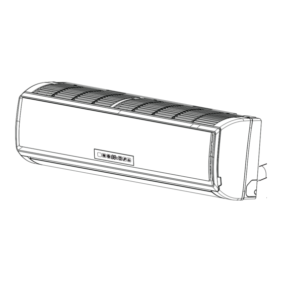
The above picture is for your reference only. Your product may look different.
Read this manual before installation.
Explain the operation or the unit to the user according to this manual.
NO.0010526879
Torque wrench
(17mm,22mm,26mm)
Pipe cutter
Flaring tool
Knife
Measuring tape
Reamer
Attention must be paid to
the rising up of drain hose
more than 10cm
more than
10cm
Selection of Installation Place
Indoor Unit - Select a plocation that is
Robust not causing vibration, where the body can be supported sufficiently.
Not affected by heat or steam generated in the vicinity, where inlet and outlet of the
unit are not disturbed.
Possible to drain easily, where piping can be connected with the outdoor unit.
Where cold air can be spread in a room evenly.
Nearby a power receptacle. (Refer to drawings).
Place where the distance of more than lm from televisions, radios, wireless apparatuses
and fluorescent lamps can be left.
In the case of fixing the remote controller on a wall, place where the indoor unit can
receive signals when the fluorescent lamps in the room are lightened.
Outdoor Unit - Select a plocation that is
Not less affected by rain or direct sunlight and is sufficiently ventilated.
Strong enough to bear the unit, where vibration and noise are not increased.
Place, where discharged wind and noise do not cause a nuisance to the neighbors.
Place, where a distance marked
G
F
Floor fixing dimensions of the
A
outdoor unit (Unit:mm)
C
Fixing of outdoor unit
D
E
more than15cm
is available as illustrated in the above figure.
Optional parts for piping
Non-adhesive tape
A
Adhesive tape
B
Saddle (L.S) with screws
C
Connecting electric cable
D
for indoor and outdoor
E
Drain hose
F
Heating insulating material
Piping hole cover
G
Fix the unit to concrete or block
with bolts (10mm) and nuts firmly
and horizontally.
When fitting the unit to wall
surface, roof or rooftop, fix
a supporter securely with nails
or wires in consideration of
earthquake and strong wind.
If vibration may affect the
house, fix the unit by attaching a
vibration-proof mat.
Advertisement
Table of Contents

Subscribe to Our Youtube Channel
Related Manuals for Haier HSU12VHJ - annexe 1


Summary of Contents for Haier HSU12VHJ - annexe 1
-
Page 1: Installation Manual Of Room Air Conditioner
fluorescent lamps can be left. Power Source In the case of fixing the remote controller on a wall, place where the indoor unit can receive signals when the fluorescent lamps in the room are lightened. Before inserting power plug into receptacle, check the voltage without fail. -
Page 2: Indoor Unit
When connecting the cable before installing the indoor unit Ø60mm Insert the cord from the back side of the unit, then pull it out on the front side. Fasten the unit wire harness to the conduit holder using the lock nut. -
Page 3: Outdoor Unit
Ensure that on dirt or debris enters the pipe. Outdoor unit The standard pipe length is 5m. If it is over 7m, the function of the unit will be affected. If the pipe has to be lengthened, the refrigerant should be charged, according to 20 g/m. -
Page 4: Refrigerant Charge Label
The end is imm- It waves. The gap with the There is the bad To prevent the gas leakage, turn the service port’s cap, the valve rod’s cap for 2-way high midway. ersed in water. ground is too small smell from a ditch valve and 3-way’s a little more than the point where the torque increases suddenly. - Page 5 15cm La ilustración anterior debe utilizarse solamente como referencia. Puede que su aparato no coincida exactamente con ella. Lea este manual antes de la instalación Explique el uso del aparato al usuario siguiendo las instrucciones de este manual.
- Page 6 1. Pase la manguera aislante a través del hueco de los materiales de aislamiento Accesorios de calor de la unidad interior. 2. Inserte los cables eléctricos de interior / exterior a través de la parte trasera de la unidad interior y tire de ellos desde la parte delantera. A continuación, conéctelos. Manguera de Control remoto (1) 3.
- Page 7 1. Retire el tapón del puerto de mantenimiento de la válvula de 3 vías, el tapón del vástago de la válvula de 2 vías y 3 vías, y conecte el puerto de mantenimiento a la Conexión de los tubos manguera de proyección de carga (inferior) del colector.
- Page 8 7. Para evitar fugas de gas, gire el tapón del puerto de mantenimiento y el tapón del vástago de las válvulas de 2 y 3 vías un poco por encima del punto en el que la Deposite agua en la bandeja de drenaje de la unidad interior y confirme que el torsión aumenta súbitamente.
- Page 9 60cm plus de 15cm L'illustration ci-dessus est indiquée à titre de référence uniquement. Il est possible que votre produit soit différent. Lisez ce manuel avant de procéder à l'installation. Communiquez à l'utilisateur suffisamment d'informations sur l'exploitation de l'unité selon ce manuel.
- Page 10 REMARQUE : L’épaisseur de la paroi des tuyaux doit être d’au moins 0,8 mm. direction de la tuyauterie et cintrez ensuite le tuyau selon la position du trou dans le mur. Lors du cintrage, prenez soin de ne pas écraser les tuyaux.
-
Page 11: Unité Extérieure
Assurez-vous qu'aucune impureté ni débris ne sont entrés dans le tuyau. La longueur standard du tuyau est de 5 m. Au delà de 7 m, l'unité ne fonctionnera pas Unité extérieure correctement. S'il faut rallonger le tuyau, le réfrigérant doit être chargé selon 20 g/m. - Page 12 Tournez le robinet de la vanne dans le sens antihoraire. 7. Pour empêcher toute fuite de gaz, tournez le capuchon de l'orifice d'entretien, le capuchon du robinet des vannes à 2 et 3 voies un peu au-delà du point où le couple augmente brusquement.
Need help?
Do you have a question about the HSU12VHJ - annexe 1 and is the answer not in the manual?
Questions and answers