
Subscribe to Our Youtube Channel
Related Manuals for BLAUBERG S37


Summary of Contents for BLAUBERG S37
- Page 1 AutomAtic control system for BlAuAir S37 (KVENT Medium) S38 (KVENT Medium, TH-TUNE) S39 (KVENT Medium, PGDE) USER'S MANUAL...
-
Page 2: Table Of Contents
Control ......................................... 23 This user’s manual is a main operating document intended for technical, maintenance, and operating staff. The manual contains information about purpose, technical details, operating principle, design, and installation of the S37, S38, S39 unit and all its modifications. -
Page 3: Purpose
THE PRODUCT MUST BE DISPOSED SEPARATELY AT THE END OF ITS SERVICE LIFE. DO NOT DISPOSE THE UNIT AS UNSORTED DOMESTIC WASTE. PURPOSE The automatic control system is designed to control a range of different ventilation system configurations. -
Page 4: S37 (Kvent Medium) Control Unit
S37 (KVENT MEDIUM) CONTROL UNIT Control unit for single-phase units connectible with RNS-5.1... - Page 5 Designation Control panel Function Value Supply fan's power supply protection 1.6A Extract fan's power supply protection 1.6A Circulation pump and temperature controller’s power supply protection 2.5A Controller, sensor and actuators’ 24 VAC power supply protection 3.15A S37-1P-.170/.170 s/f...
- Page 6 Control unit for single-phase units connectible with RNS-12 Q1 Q2...
- Page 7 Designation Control panel Function Value Supply fan's power supply protection 1.6A Extract fan's power supply protection 1.6A Circulation pump and temperature controller’s power supply protection 2.5A S37-1/3P-.170/.170 s/f Controller, sensor and actuators’ 24 VAC power supply protection 3.15A...
- Page 8 Control unit for three-phase units connectible with RNS-12 Q1 Q2...
- Page 9 Designation Control unit Function Value Power supply protection of the supply and exhaust fans Circulation pump and temperature controller’s power supply protection 2.5A Controller, sensor and actuators’ 24 VAC power supply protection 3.15A S37-3P-1.32/1.32 s/f Power supply protection of the 230 VAC discrete outputs and actuators...
- Page 10 Table of single-phase units connectible with RNS-5.1 Automation system Ventilation unit Electr. parameters Control unit BL-B190B-EC03 230 VAC, 170 W, 1.3 A CF 500 BL-B190B-EC03 230 VAC, 170 W, 1.3 A BL-B190B-EC03 230 VAC, 170 W, 1.3 A...
- Page 11 Table of single-phase units connectible with RNS-12 Automation system Ventilation unit Electr. parameters Control unit BL-B190B-EC03 230 VAC, 170 W, 1.3 A CF 500 BL-B190B-EC03 230 VAC, 170 W, 1.3 A BL-B190B-EC03 230 VAC, 170 W, 1.3 A...
- Page 12 Replacement table of fuses and their analogs for single-phase fan power supply Rated current [A] Manufacturing factory LITTELFUSE EATON/BUSSMANN ESKA Equipment code 0218002.MXP BK1-S506-2-R 522.520 Breaking current Circuit breaker size 5x20mm Circ. breaker characteristic Slow Rated current [A] 3.15...
- Page 13 Replacement table of fuses and their analogs for three-phase fan power supply Rated current [A] Manufacturing factory DF ELECTRIC Equipment code 2610005 420506 Breaking current 50 kA 20 kA Circuit breaker size 8X31 mm Circ. breaker characteristic...
- Page 14 S37 (KVENT Medium) controller inputs / outputs Display FieldBus2 FieldBus1 port/BMS /BMS Display port Ethernet Field bus +Vdc NO10 NO11 NO12 EEV2 EEV1 ID10 Pos. Description Pos. Description Digital inputs Micro USB to update applications, import and export settings and error log...
-
Page 15: Wiring
WIRING DISCONNECT THE POWER SUPPLY PRIOR TO ANY OPERATIONS WITH THE UNIT. THE UNIT MUST BE CONNECTED TO POWER MAINS BY A QUALIFIED ELECTRICIAN. ANY TAMPERING WITH THE INTERNAL CONNECTIONS IS PROHIBITED AND WILL VOID THE WARRANTY. - Page 16 External wiring diagram for single-phase units connectible with RNS-5.1 ~230V Reserve AI 4..20mA N L L1 N L L1 -t° -t° -t° POWER **M1 **M2 SM1(2) FCP1 DPT1 ~230V Control board CCU1 ~ Y U ~ Y U...
- Page 17 External wiring diagram for single-phase units connectible with RNS-12 ~400V Reserve AI 4..20mA N L L1 N L L1 -t° -t° -t° POWER **M1 **M2 SM1(2) FCP1 DPT1 ~400V Control board CCU1 ~ Y U ~ Y U...
- Page 18 External wiring diagram for single-phase units connectible with RNS-12 ~400V Reserve AI 4..20mA N L L1 N L L1 -t° -t° -t° POWER **M1 **M2 SM1(2) FCP1 DPT1 ~400V Control board CCU1 ~ Y U ~ Y U...
- Page 19 External wiring diagram designation key General equipment Designation Name Control terminal Inline CO2 sensor DPT1 Supply air flow sensor FCP1 Fire alarm (customer’s equipment) Supply air fan Extract air fan POWER Power supply from the customer's feeder...
-
Page 20: Th-Tune And Pgde Control Panels
TH-TUNE AND PGDE CONTROL PANELS TECHNICAL DATA Value Parameter th-Tune pGDE Storage temperature [°C] -20...+70 -20...+70 Storage humidity [%] 10...90 (no condensation) 10...90 (no condensation) Operation temperature [°C] -10...+60 -20...+60 Operation humidity [%] 10...90 (no condensation) 10...90 (no condensation) -
Page 21: Installation And Set-Up
INSTALLATION AND SET-UP Installation of the th-Tune control panel Use a mounting box of at least 65 mm in diameter and at least 31 mm deep to install the back side of the panel. 1. Use a screwdriver to separate the front and back sides of the 2. - Page 22 Installation of the pGDE control panel Connect the pGDE control panel to the controller using the 6P6C phone connector (PLUG-6P6C-P-C2). The maximum telephone cable length is 50 m. Route the telephone cable to the installation site to install the control panel on the wall.
-
Page 23: Control
CONTROL Th-Tune control Panel BUTTON FUNCTIONS Standby/auto mode. Disables the Boost function. (MODE) Unit change: ECO, PRECOMFORT, COMFORT, STOP. (FAN) To turn the schedule mode on/off: hit the button. To access the schedule menu, press and hold the button for 2 seconds. Use (CLOCK) the rotating handle to select options. - Page 24 The description of unit operation modes STOP – the fans are off, the protective functions are operating (the field 3 shows no indication). ECO – the fan speed is low, reduced power consumption and temperature. PRECOMFORT — medium fan speed, temperature and power consumption.
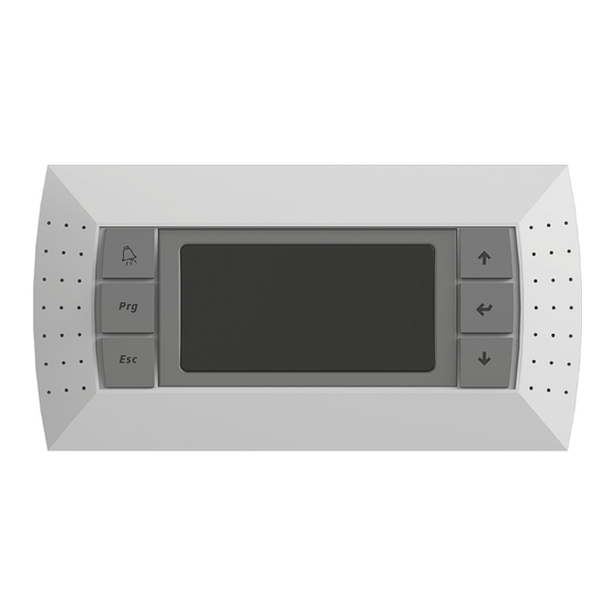
- Page 25 The panel has 6 buttons: (ALARM) — to manually reset alarm signals. (PRG) — to change the operating mode. (ESC) — to return to the previous menu screen. (UP, DOWN) — to switch between the display screens or increase / decrease values.
- Page 26 6. The preset indoor or supply duct temperature setpoint (based on the settings). 7. Indicates access to user menu by means of UP, DOWN and ENTER buttons for confirmation. INFO — displays the general status of devices, physical status of device and sensor inputs and outputs.
- Page 27 ALARMS In case of an alarm, the alarm signal screen is displayed. Item Description Alarm No. / Alarms total Date and time of alarm Alarm code Alarm description Alarm-triggered sensor value. Alarms can be reset manually, automatically, or automatically on a regular basis.
- Page 28 If control is performed via BMS, the I005 Enable thTune management parameter must be set to 0. Alarms Alarm Alarm description Reset Action code A000 Supply temperature probe not working Auto reset Stop unit A001 Cooling device alarm...
- Page 29 A035 Fans overload alarm Auto reset Stop unit A036 Supply humidity probe not working Auto reset Stop humidifier A037 Unit configuration not allowed Auto reset Stop unit A038 Supply fan - Offline Auto reset Stop unit...
- Page 30 A086 Extract fan - Earth-GND fault User reset Stop unit A087 Extract fan - Peak current error User reset Stop unit A088 Extract fan - Hall sensor error User reset Stop unit A089 Extract fan - Offline...
- Page 31 Password control There are three password levels: 1. Service: read only access to all parameters By default the password is 0000. 2. Maintenance: read only access to all parameters, but some can be modified. By default the password is 0001.
- Page 32 Standard configuration names For configurations equipped with a plate heat exchanger For configurations equipped with a rotary heat exchanger Configuration Filename Configuration Filename CFX-0-0 EXPORT_20 RX-0-0 EXPORT_30 CFX-0-CW EXPORT_21 RX-0-CW EXPORT_31 CFX-0-CDX EXPORT_22 RX-0-CDX EXPORT_32 CFX-HW-0...
- Page 33 The automated system can also operate autonomously with no remote controller. The control unit has an in-built WEB interface, and supports Modbus and Bacnet protocols through RS485 and Ethernet interfaces. The information on protocol settings is specified in the controller’s user manual.
- Page 34 www.blaubergventilatoren.de...
- Page 35 www.blaubergventilatoren.de...
- Page 36 www.blaubergventilatoren.de B280EN-01...
Need help?
Do you have a question about the S37 and is the answer not in the manual?
Questions and answers