Table of Contents
Advertisement
Quick Links
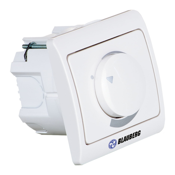
Speed controller CDT E/0-10
DESCRIPTION
The speed controller CDT E/0-10 (hereinafter the controller) is designed for smooth air flow
control in the ventilation unit. The air flow control is carried out from zero to the maximum
value by means of rotating the control knob.
TECHNICAL DATA
Parameter
Power supply voltage [V]
Control voltage outlet [V]
Cable cross section [mm
]
2
Temperature range [°C]
Max. humidity range [%]
IP on the front panel side
Weight [g]
CONTROLLER DESIGN
Modification for wall flush mounting
OVERALL AND CONNECTION DIMENSIONS
78
ELECTRIC CONNECTIONS
WARNING!
Turn off power supply prior to any operations with the unit. Any installation, extension, redesign and technical maintenance operations
must only be performed by qualified technicians possessing valid work permit for electrical works.
+48V
+10V
CTR
GND
Connection to DC mains with 10 V power voltage
Value
+48 or +10
0–10
0.5
+1...+35
80
IP40
120
68
Controller wiring diagrams
+10V DC
0-10V
GND
1
Modification for wall surface mounting
+48V
+10V
CTR
GND
Connection to DC mains with 48 V power voltage
80
+48V DC
0-10V
GND
Advertisement
Table of Contents

Subscribe to Our Youtube Channel
Related Manuals for BLAUBERG CDT E/0-10


Summary of Contents for BLAUBERG CDT E/0-10
- Page 1 Speed controller CDT E/0-10 DESCRIPTION The speed controller CDT E/0-10 (hereinafter the controller) is designed for smooth air flow control in the ventilation unit. The air flow control is carried out from zero to the maximum value by means of rotating the control knob.
- Page 2 The minimum fan rotation speed is set with the R3 potentiometer located on the control board of the speed controller. MOUNTING (based on the modification for the wall flush mounting) WARNING! Make sure that the speed controller is not damaged. Do not use a damaged controller! Do not install the controller on an uneven surface! Do not apply undue force while tightening the screws to avoid the unit deformation.
- Page 3 4. Connect the cable to the speed controller in compliance with the wiring diagram. Insert the speed controller in the mounting box using the self-tapping screws. 5. Install the front panel of the speed controller as follows: install the front panel, fix the front panel using a washer and a nut, fix the control knob.
- Page 4 DELIVERY SET Name Quantity Speed controller 1 pc. User’s manual 1 pc. Fastening kit 1 pc. Packing box 1 pc. MANUFACTURER’S WARRANTY Unit Type Speed controller Model CDT E/0-10 Serial Number Manufacture Date Purchase Date Warranty Period Seller Seller’s Stamp B20-2EN-04...
Need help?
Do you have a question about the CDT E/0-10 and is the answer not in the manual?
Questions and answers