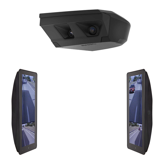
ARCOL eMirror System And Installation Manual
Camera monitor system
Hide thumbs
Also See for eMirror:
- User manual (6 pages) ,
- System and installation manual (22 pages) ,
- User manual (4 pages)
Table of Contents
Advertisement
Quick Links
Advertisement
Table of Contents

Related Manuals for ARCOL eMirror


Summary of Contents for ARCOL eMirror
- Page 1 Camera Monitor System System and Installation Manual English V 07/2023...
-
Page 2: Table Of Contents
9.4 eMirror System connection diagram Cat. II / IV / Va 9.4 eMirror System connection diagram Cat. II / IV / Va coupled monitor 9.4 eMirror System connection diagram Cat. II / IV / Va & VIa coupled monitor 9.7 Observations 10. -
Page 3: System Description
Camera cable Heated cable Heated cable 12V/24V power supply 12V/24V power supply Figure 1.1 Figure 1.2 eMirror system Cat. II / IV / V Class V Camera Monitor 12,3" Class IV Camera Class II Class II Camera Class IV Class V... - Page 4 Camera Monitor System System description eMirror system Cat. II / IV / Va coupled monitor eMirror system Cat. II / IV / Va & VIa coupled monitor Monitor 7" Monitor 7" Class II Class II Class V Class V&VI...
-
Page 5: Categories
Camera Monitor System 2. Categories 2.1. eMirror Class II The Class II field of vision of the main mirror device shows the driver a width of 5 m which is delimited by a plane parallel to the vertical longitudinal median plane and passing through the outermost point of the vehicle from a point 30 m behind the driver's ocular points towards the horizon. -
Page 6: Camera Unit Fixing Points
Camera Monitor System 3. Camera unit fixing points Left Side / Right Side Units en mm 8,9 (x3) Wire pass-through Scale 1:1 English V 07/2024 6 of 29... -
Page 7: Camera Unit
Camera Monitor System 4. Camera Unit 4.1 Vehicle mounting position The positioning and placement of the cameras is essential for the correct functioning of the system. It is recommended that the camera unit is fully coupled to the bodywork, avoiding leaving a gap between the two as elements may collide with it and become trapped causing damage to the system. -
Page 8: Mounting Instructions Camera Unit
Camera Monitor System Mounting Instructions Camera Unit 5.1 Camera unit mounting Cat. II / IV Right Side / Left Side Symmetrical Step 1 1.1 Pass cables through the bracket DIN 965 M4x10 (x2) DIN 965 M4x16 (x2) Minimum cable bending radius... - Page 9 Camera Monitor System 5.2 Camera unit mounting Cat. II / V Right Side / Left side UK version symmetrical Step 1 DIN 965 M4x10 (x2) 1.1 Remove Class V Camera DIN 965 M4x16 (x2) PH2-cross recess Step 2 2.1 Pass cables through the bracket...
- Page 10 Camera Monitor System Step 5 Step 6 5.1 Making connections 6.1 Fasten cables *System connection, see page 19 Step 7 7.1 Place cover 7.2 Fasten with PH2 (Phillips) DIN 965 M4x16 DIN 965 M4x10 Clipping system 10 of 29...
-
Page 11: Camera Unit Mounting Cat. Ii / Iv
Camera Monitor System 5.3 Camera unit mounting Cat. II / IV / V Right Side / Left side UK version symmetrical Step 1 DIN 965 M4x10 (x2) DIN 965 M4x16 (x2) 1.1 Remove Class V Camera PH2-cross recess Step 2 2.1 Pass cables through the bracket... - Page 12 Camera Monitor System Step 5 Step 6 5.1 Making connections 6.1 Fasten cables *System connection, see page 20 Step 7 7.1 Place cover 7.2 Fasten with PH2 (Phillips) DIN 965 M4x16 DIN 965 M4x10 Clipping system 12 of 29...
-
Page 13: Camera Unit Mounting Cat. Ii / Iv / Va
Camera Monitor System 5.4 Camera unit mounting Cat. II / IV / Va coupled monitor Right Side / Left side UK version symmetrical Step 1 DIN 965 M4x10 (x2) 1.1 Pass cables through the bracket DIN 965 M4x16 (x2) -
Page 14: Monitor
Camera Monitor System 6. Monitor 6.1 Mounting position The positioning and placement of the monitor is essential for the correct operation of the system. The position of both monitors, on the driver and passenger sides, should be perpendicular to the horizontal plane passing through the centres of the monitor and the driver's eyes (see Figure 6.1). -
Page 15: Monitor Assembly Instruction
3.1 Fasten cables 4.1 Insert the monitor into the stand 3.2 Place cover H2-cross recess Do not block the ventilation holes of the monitor **Optional VESA 35X75 fixing provided by Arcol Step 5 Step 6 5.1 Find the right position 6.1 Fasten... -
Page 16: Monitor Mounting 7" Class Va / Va & Via
Camera Monitor System 7.2 Monitor mounting 7" Class Va / Va & VIa The monitor has three possible fixing systems to the vehicle. *System Connection II / IV / Va, see page 21 and 22. Coupled monitor see page 23 and 24. -
Page 17: Monitor Mounting 7" System Coupled Monitor
Camera Monitor System 7.3 Monitor mounting 7" coupled monitor system *System connection II / IV / Va coupled monitor, see page 23 and 24 *System connection II / IV / Va & VIa coupled monitor, see page 25 and 26... -
Page 18: Connections
Camera Monitor System 8. Connections 8.1 eMirror category II / IV system connection Class II / IV power supply Terminal Colour Function Voltage Signal Blue Ground (-) Yellow Battery (+) 12V/24V KL 30 Brown System ON / OFF 12V/24V... -
Page 19: Emirror Category Ii / V System Connection
Camera Monitor System 8.2 eMirror category II / V system connection Class II / V power supply Terminal Colour Function Voltage Signal Blue Ground (-) Yellow Battery (+) 12V/24V KL 30 Brown System ON / OFF 12V/24V KL 15... -
Page 20: Emirror Category Ii / Iv / V System Connection
Camera Monitor System 8.3 eMirror category II / IV / V system connection Class II / IV / V power supply Terminal Colour Function Voltage Signal Blue Ground (-) Yellow Battery (+) 12V/24V KL 30 Brown System ON / OFF... -
Page 21: Emirror Category Ii / Iv / Va System Connection
Camera Monitor System 8.4 eMirror category II / IV / Va system connection Class II / IV / Va system connection Terminal Colour Function Voltage Signal Blue Ground (-) Yellow Battery (+) 12V/24V KL 30 Brown System ON / OFF... - Page 22 Camera Monitor System eMirror category II / IV / Va system connection Monitor 7" Power supply Terminal Colour Function Voltage Signal Black Ground (-) Battery (+) 12V/24V Power Gray Trigger 1 12V/24V Trigger 1 Green Trigger 2 12V/24V Trigger 2...
-
Page 23: Emirror Category Ii / Iv / Va Coupled Monitor System Connection
Camera Monitor System 8.5 eMirror category II / IV / Va coupled monitor system connection Class II / IV / Va with Monitor coupled system connection Terminal Colour Function Voltage Signal Blue Ground (-) Yellow Battery (+) 12V/24V KL 30... - Page 24 Camera Monitor System eMirror category II / IV / Va coupled monitor system connection Monitor 7" Power supply Terminal Colour Function Voltage Signal Black Ground (-) Battery (+) 12V/24V Power Blue Trigger 1 12V/24V Trigger 1 Green Trigger 2...
-
Page 25: Emirror Category Ii / Iv / Va & Via Coupled Monitor System Connection
Camera Monitor System 8.6 eMirror category II / IV / Va & VIa coupled monitor system connection Class II / IV / Va & VIa coupled monitor system connection Terminal Colour Function Voltage Signal Blue Ground (-) Yellow Battery (+) - Page 26 Camera Monitor System eMirror category II / IV / Va & VIa coupled monitor system connection Monitor 7" Power supply Terminal Colour Function Voltage Signal Black Ground (-) Battery (+) 12V/24V Power Blue Trigger 1 12V/24V Trigger 1 Green...
-
Page 27: Emirror System Connection Diagram
COAX. CABLE CAM CLASS IV------------------------------------------------------------------------------COAX. CABLE CAM CLASS IV COAX. CABLE CAM CLASS V------------------------------------------------------------------------------COAX. CABLE CAM CLASS V HEATER CAM-------------------------------------------------------------------------------HEATER CAM CLASS II ---HEATER CAM CLASS IV 9.5 eMirror System connection diagram Cat. II / IV / Va coupled monitor DIN MONITOR------------------------------------------------------------------------------DIN CAMERA GND------------------------------------------------------------------------------GND KL-15------------------------------------------------------------------------------KL-15 KL-30------------------------------------------------------------------------------KL-30 COAX. -
Page 28: Emirror System Connection Diagram Cat. Ii / Iv / Va & Via Coupled Monitor
---HEATER CAM CLASS IV 9.7 Observations The eMirror system must always be connected to the battery. The system will display the image in less than 7 seconds once the System ON/OFF signal goes from 0V to 12V/24V. The System ON/OFF line must remain in the ON position for 420 seconds after the vehicle is turned off. -
Page 29: Changelog File
Camera Monitor System 10. Changelog file V 06/2023: - Modification of the distances from the driver's eye to the monitors according to extension 01 of the eMirror system approval (see page 14) : Driver side: is 940 was 800 mm...
Need help?
Do you have a question about the eMirror and is the answer not in the manual?
Questions and answers