
Subscribe to Our Youtube Channel
Related Manuals for Smeg SA661X


Summary of Contents for Smeg SA661X
- Page 1 � � � � � � and operating technology with style instructions SA661X ceramic cooktop...
-
Page 2: Table Of Contents
Contents INSTRUCTIONS FOR PROPER USE ______________________________________ 19 SAFETY INSTRUCTIONS _______________________________________________ 20 KNOW YOUR HOB ____________________________________________________ 21 BEFORE FIRST USE___________________________________________________ 21 COOKING ZONES_____________________________________________________ 22 DESCRIPTION OF CONTROL ON THE FRONT CONTROL PANEL______________ 23 USE OF THE COOKING HOB____________________________________________ 24 CLEANING AND MAINTENANCE _________________________________________ 28 SOMETHING WRONG? ________________________________________________ 28 10. -
Page 3: Instructions For Proper Use
ELECTRICAL APPLIANCES BE INSTALLED AND SERVICED BY COMPETENT PERSONS, WHO WILL COMPLY WITH THE RELEVANT STANDARDS AND REGULATIONS. SMEG REGISTERED INSTALLERS UNDERTAKE TO WORK TO SATISFCTIORY STANDARDS. DISCONNECTION OF GAS AND ELECTRIC APPLIANCES SHOULD ALWAYS BE CARRIED OUT BY COMPETENT PERSONS... -
Page 4: Safety Instructions
Safety instruction 2. SAFETY INSTRUCTIONS INSTRUCTIONS FOR THE INSTALLER: THESE ARE INTENDED FOR THE QUALIFIED TECHNICIAN WHO MUST INSTALL THE APPLIANCE, SET IT FUNCTIONING AND CARRY OUT AN INSPECTION TEST. IT IS OBLIGATORY FOR THE ELECTRICAL SYSTEM TO BE GROUNDED ACCORDING TO THE METHODS REQUIRED BY SAFETY RULES. -
Page 5: Know Your Hob
Instructions for the user 3. KNOW YOUR HOB Glass surface of the appliance Single cooking zone Dual oval cooking zone Dual round cooking zone Timer controls Control panel Triple cooking zone Heating zone NOT ALL COMPONENTS DESCRIBED ARE PRESENT ON ALL MODELS 4. -
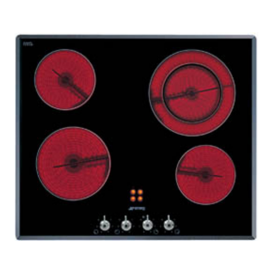
Page 6: Cooking Zones
Instructions for the user 5. COOKING ZONES The appliance features 4/5 cooking zones of different diameter and power. Their position is clearly indicated by circles and the heat given off is defined by the markings on the glass surface. The 5 cooking zones are of the HIGH-LIGHT type and come on after a few seconds of being activated. -
Page 7: Description Of Control On The Front Control Panel
Instructions for the user 6. DESCRIPTION OF CONTROL ON THE FRONT CONTROL PANEL All the hob controls are grouped together on the front panel. The table below provides a description of the symbols used. HOB IGNITION OVAL COOKING ZONE CONTROLS ON-OFF REAR RIGHT-HAND COOKING ZONE VALUE INCREASE BUTTON FRONT RIGHT-HAND COOKING... -
Page 8: Use Of The Cooking Hob
Instructions for the user 7. USE OF THE COOKING HOB 7.1 Hobs with knobs 7.1.1 Single cooking zones Each knob shows the cooking zone it is for. For example, the symbol identifies the knob that controls the rear right-hand cooking zone. To heat, turn the knob to the desired position (1 to 6). - Page 9 Instructions for the user 7.2 Hobs with touch-control buttons When an icon is pressed the unit beeps to confirm. To operate the panel of the hobs equipped with touch-controls, lightly press the icons printed on its surface. On first connection to the electrical mains, an operating check will be carried out automatically and all the indicator lights will come on for a few seconds.
- Page 10 Instructions for the user 7.2.8 Timer (on some models only) Some models are equipped with a 1 to 99-minute cooking timer. To use the timed cooking, first set the power level by following the instructions given in paragraphs “7.2.2 Single Cooking Zones” and “7.2.3 Dual Cooking Zones”. Now, with the hob NOT locked out (if it is locked out, press the key to enable the functions), press the symbol...
- Page 11 Instructions for the user 7.2.14 Switching off To switch the hob off, hold down for 1 second; this deactivates all cooking zones even if they are in use or the lock-out function is active, and the hob will turn off completely. If the cooking zones have just been used, will start flashing a few seconds after the hob is turned off to warn that they are still hot.
-
Page 12: Cleaning And Maintenance
Instructions for the user 8. CLEANING AND MAINTENANCE Before any intervention, disconnect the power supply of the device. 8.1 Cleaning the ceramic hob The hob should be regularly cleaned; preferably after every use, once the residual heat warning lights have gone off. Smudges from aluminium-bottom pans can be easily cleaned off with a cloth dampened in vinegar. -
Page 13: Installation
Instructions for the installer 10. INSTALLATION 10.1 Technical information Hob type See rating plate Electrical connections 220-240V~ 50/60Hz / 380-415V 2N∼ 50/60Hz / 380-415V 3N∼ 50/60Hz Electric HOB RATING Maximum electrical power See rating plate DIMENSIONS OF THE HOB Width (mm) Depth (mm) 10.2 The rating plate Make sure that the voltage and capacity of the power... - Page 14 Instructions for the installer ∼ For operation on 380-415 V 3N : use an - H05V2V2-F type five-core cable (5 x 1,5 mm ∼ For operation on 380-415 V 2N : use an - H05V2V2-F type four-core cable (4 x 2,5 mm ∼...
- Page 15 Instructions for the installer 10.4 POSITIONING OF THE HOB The following operation requires building and/or carpentry work so must be carried out by a competent tradesman. Installation can be carried out on various materials such as masonry, metal, solid wood or plastic laminated wood as long as they are heat resistant (T 90°C).
- Page 16 Instructions for the installer The diagrams illustrate the cutting sizes and additional shaping required for the installation hole if you decide to install the hob flush with the work-top surface. The work-top hole and shaping dimensions are purely guideline; it is essential to refer to your actual ceramic hob before making any cuts. After you have attached the adhesive strip supplied with the hob to the underside of the glass (A) position the hob precisely and centrally in the cut out, and mount it with the mounting brackets.
Need help?
Do you have a question about the SA661X and is the answer not in the manual?
Questions and answers