Table of Contents
Advertisement
Advertisement
Table of Contents

Related Manuals for Pioneer DJM-700


Summary of Contents for Pioneer DJM-700
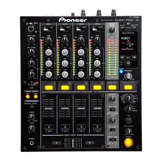
- Page 1 DJ MIXER DJM-700-S DJM-700-K Operating Instructions...
- Page 2 In some countries or regions, the shape of the power plug and power outlet may sometimes differ from that shown in the explanatory drawings. However the method of connecting and operating the unit is the same.
-
Page 3: Table Of Contents
Operating Environment We Want You Listening For A Lifetime Operating environment temperature and humidity: +5 ºC – +35 ºC (+41 ºF – +95 ºF); less than 85 %RH Used wisely, your new sound equipment will (cooling vents not blocked) provide a lifetime of fun and enjoyment. Since... -
Page 4: Confirm Accessories
Analog signals are transmitted by the shortest circuitry and Operating Instructions........1 converted to digital format at 96 kHz sampling rate via a 24-bit high quality A/D converter. -
Page 5: Connections
The sound level from these connectors is controlled independently by the BOOTH MONITOR LEVEL dial, regardless of the position of Use to set the sampling frequency of the digital output to 96 kHz/ the MASTER LEVEL dial. 24-bit format or 48 kHz/24-bit format. -
Page 6: Connecting Inputs
CONNECTIONS Always turn off the power switch and disconnect the power plug from its outlet when making or changing connections. CONNECTING INPUTS Pioneer DJ CD players Connect the ground wire from an analog turntable to the SIGNAL GND terminal of the DJM-700-S/DJM-700-K. -
Page 7: Connecting External Effectors, Output Connectors
DJ mixer’s L channel output. In this way, the mixed L+R audio Unbalanced output supporting RCA-type plug. The sound volume signal will be sent to the effector. In the same way, use a cable with for this output is controlled by the BOOTH MONITOR LEVEL dial, Ø6.3 mm phone plugs to connect the DJ mixer’s RETURN... -
Page 8: About Midi Connectors
– – – – – – MIDI OUT TALK OFF ON OVER FADER START CH-1 CH-2 CONNECTING THE POWER CORD Connect the power cord last. • After completing all other connections, connect the power plug to an ordinary AC outlet. -
Page 9: Names And Functions Of Parts
Microphone 1 level control dial (MIC 1 LEVEL) other than that from the microphone is attenuated by 20 dB. Use to adjust the volume of microphone 1. (adjustable range – to • When not using the TALK OVER function, it is recommended to 0 dB) set the switch to the [OFF] or [ON] position. - Page 10 1 and microphone 2 (if the effect selector is set to [SND/RTN], the RETURN input is also added). • When the CROSS FADER ASSIGN switch is set to the [A] or [B] position, fader start button operation is linked to the operation of 24 Master level indicator (MASTER L, R) the cross fader (and unlinked to channel fader).
- Page 11 MIDI snapshot SNAP The BPM is calculated from the intervals at which the TAP button is struck. If the TAP button is pressed in the AUTO mode, the mode When MIDI output function is ON MIDI On automatically switches to the TAP mode (manual input).
- Page 12 Beat display section indicator flashes. Although the display includes seven actual Displays the location of parameter 1 relative to BPM (1/1 beat). The indicators, the values of the two ends can also be considered to represent indicators, with the result that nine positions can be lower row is lighted constantly.
-
Page 13: Mixer Operations
OVER]. LEVEL TRIM • When the switch is set to [ TALK OVER ], any time a sound of over –15 dB is detected by the microphone, the output for all sound sources other than the microphone are attenuated by HI, MID, LOW 20 dB. -
Page 14: Fader Start Function
When the mixer’s channel fader lever or cross fader lever are • If a cue point has already been set, it is not necessary to set moved, the CD player is released from the pause mode and the CD player to standby at the cue point. - Page 15 Set the CD player to the desired cue point, and engage cue point standby. • If a cue point has already been set, it is not necessary to set the CD player to standby at the cue point. At the instant you wish to start playback, move the cross fader lever.
-
Page 16: Effect Functions
Auto TRANS SND/RTN) through beat effects linked to the BPM and manual In units of 1/16, 1/8, 1/4, 1/2, 1/1, 2/1, 4/1, 8/1, or 16/1 beat, the filters or effect frequency filters linked to the FREQUENCY dial. sound is automatically cut in synch with the rhythm. - Page 17 When ROBOT is applied to microphone sound, a voice- Example changer effect is produced. CRUSH Allows rapid creation of cyclically changing “crush sound effect” in beats of 1/4, 1/2, 1/1, 2/1, 4/1, 8/1, 16/1, 32/1, or 64/1. Original Example Effect ON Time...
-
Page 18: Producing Beat Effects
“1/1” (or “4/1”, depending on the effect selected), Rotating the LEVEL/DEPTH (PARAMETER 2) dial adjusts the and the time for 1 beat (1/4 notes) or 4 beats will be set as quantitative parameter for the selected effect. the effect time. -
Page 19: Manual Filter Operation
Press the FILTER button so that it lights. • When the beat effect type is set to ROLL, REVERSE ROLL, UP • Confirm that the FILTER button lights steadily. ROLL, or DOWN ROLL, the beat effect’s output sound becomes •... -
Page 20: Effect Parameters
(*1) When the effect channel selector is set to [CF.A], [CF.B], or [MASTER], even if the effect monitor is turned ON, if the selected channel’s sound is not output to the master output, the effect sound will not be heard. -
Page 21: Midi Settings
• Synch may not be achieved if the track’s BPM cannot be detected and measured stably. • BPM values set with the TAP mode can also be used to output the timing clock. =120 Press the MIDI START/STOP button. -
Page 22: Midi Messages
MIDI SETTINGS MIDI MESSAGES MIDI Message Category Switch Name Switch Type Commnets 0 to 127 0 to 127 0 to 127 BUTTON OFF=0, ON=127 FADER 0 to 127 CF ASSIGN 0, 64, 127 0 to 127 0 to 127 0 to 127... - Page 23 OFF=0, ON=127 EFFECT KIND See “PROGRAM CHANGE” below. CH SELECT TIME PARAMETER 1 value; FLANGER, PHASER, FILTER, CRUSH changed to 1/2 value; minus values are converted to positive. LEVEL/DEPTH 0 to 127 EFFECT ON/OFF BUTTON OFF=0, ON=127 0 to 127...
-
Page 24: Program Change
MASTER SNAPSHOT Once the DJM-700-S/DJM-700-K is setup with parameters for a given purpose, that set of parameters can be recorded as a snapshot. When snapshot of the current status is recorded, all messages for control change and program change are transmitted. -
Page 25: Troubleshooting
• MIDI sequencer is not supported type. • MIDI sequencers that do not support MIDI timing clock cannot be synchronized. Static electricity or other external interference may cause the unit to malfunction. To restore normal operation, turn the power off and then on again. -
Page 26: Specifications
A/D, D/A converter ........24 bits... -
Page 27: Block Diagram
BLOCK DIAGRAM BLOCK DIAGRAM... - Page 28 All rights reserved. PIONEER CORPORATION 1-1, Shin-ogura, Saiwai-ku, Kawasaki-shi, Kanagawa 212-0031, Japan PIONEER ELECTRONICS (USA) INC. P.O. BOX 1540, Long Beach, California 90801-1540, U.S.A. TEL: (800) 421-1404 PIONEER ELECTRONICS OF CANADA, INC. Industrial Products Department: 300 Allstate Parkway, Markham, Ontario L3R OP2, Canada...
Need help?
Do you have a question about the DJM-700 and is the answer not in the manual?
Questions and answers