Table of Contents
Advertisement
Quick Links
Advertisement
Table of Contents

Related Manuals for PCE Instruments PCE-PA 7500


Summary of Contents for PCE Instruments PCE-PA 7500
- Page 1 OPERATION MANUAL PCE-PA 7500 POWER ANALYZER...
-
Page 2: Table Of Contents
Table of Contents Chapter 1 Overview ....................1 Profile ......................1 Open package inspection ..............1 Use co n d i t i o n ..................... 2 1.3.1 Power connection ................2 1.3.2 Fuse ......................2 1.3.3 Environment ..................... 2 1.3.4 Preheat ....................2 Instrument and other characteristics ........... -
Page 3: Chapter 1 Overview
According to the different instrument models, some instruments do not have harmonic analysis functions. PCE-PA 7500 two channel power analyzer, It covers the advantages of a larger input bandwidth (10 ~ 100Hz). At the same time, the Handler interface, RS232C/ RS485 interface, and USBTMC and USBCDC interfaces of the instrument. -
Page 4: Use Condition
The front panel of the instrument is marked with the specific model and the main measurement scope of the instrument. Check whether the model you ordered is consistent. Please confirm it according to the packing list. Instrument models and basic functions in Table 1-1: Note: It is best to keep the packaging box properly after opening the box, to avoid the instrument causing unnecessary damage due to the unsuitable packaging box in the future transportation. -
Page 5: Chapter 2 The Front/Rear Panel Description And Entry Operation
Press to modify the corresponding parameter value. Model bar Shows device model, brand information POWER Power switch Figure 2-1 front panel description Rear panel description Figure 2-2 briefly description on the rear panel of the PCE-PA 7500... -
Page 6: Chapter 3 Basic Operation Instructions
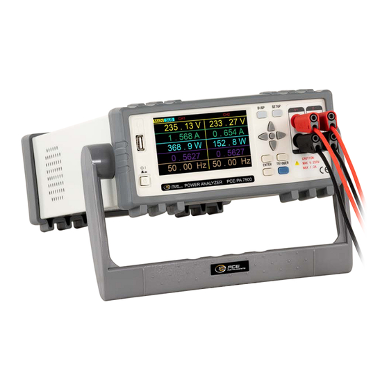
Figure 3-1 shows the display screen of PCE-PA 7500 Display area definition PCE-PA 7500 uses 24 -bit color 4.3 -inch color LCD screen with a resolution of 480 × 272. The content of the screen display is divided into the following display area,... - Page 7 3-1:Main parameter display screen 3-2:Sub-parameter display screen The meaning of each area is shown in Table 3-1 Channel 1 parameter This column shows the parameter of Channel 1 Channel 2 parameter This column shows the parameter of Channel 2 Voltage value This row shows the voltage value of each channel Current value This row shows the current value of each channel...
-
Page 8: Display Interface Switch
Display interface switch The DISP button and the Setup button are the most frequent two buttons in the page switching process, which are entrances to the test related page and setting related pages. 3.3.1 Measurement display button DISP Press DISP button, enter the measurement display homepage 3.3.2 Measurement setting button SETUP Press SETUP button, enter the system setting homepage... -
Page 9: Chapter 4 System Settings
Chapter 4 System settings Press SETUP key into the system settings interface 4.1 Electric energy automatically returns to zero settings: The instrument can set the electric energy automatically to zero, set ON or OFF, the user can set it according to their own needs, the setting steps are as follows: Use the cursor key to move the cursor to the AutoZero area, press the [ENTER] key, and then press the upper and lower keys to select, "ON"... -
Page 10: Key Sound
4.3 Key sound: ON or OFF the key sound. The setting steps are as follows: Use the cursor key to move the cursor to the Beeper area, press the [ENTER] key, and then press the upper and lower keys to select. After selecting, press the [ENTER] key to complete the settings. -
Page 11: Beep Alarm Switch
Set up the current limit, It will alarm if exceed this setting value. The setting range is 00.000 ~ 20.000A. The setting steps are as follows: Use the cursor key to move the cursor to ILimit area, press the [ENTER] key, and then press the upper and lower keys to select the value, ↑add value,↓... -
Page 12: Chapter 5 Wiring Method
Chapter 5 Wiring method PCE-PA 7500 instrument provides four test wiring input terminals, namely voltage high-end, voltage low-end, load high-end, load low-end. As shown in the above figure: connect the channel 1 voltage input into the terminal 5-6 (pay attention to distinguish L/N), connect the channel 1 load to the terminal 7-8 (pay attention to distinction L/N), then Channel 1 wire connection is finished. -
Page 13: Measurement Parameters And Symbols
The main structure of PCE-PA 7500 two channel single -phase power analyzer is to input the UUT system to the Power Analyzer through the voltage and current of the Power Analyzer by Difference input. Through the amplification, filtering, sampling, and AD conversion inside the instrument, the simulation signal of the upcoming voltage and current is converted into a digital amount Ui and Ii. - Page 14 I AC The maximum value of u(t) during a sampling cycle UPK+ The minimum value of u(t) during a sampling cycle UPK- The maximum value of i(t) during a sampling cycle I PK+ The minimum value of i(t) during a sampling cycle I PK- The ratio of the maximum sampling point absolute value and the Current valid value during a sampling cycle...
-
Page 15: Instrument Parameter
6.2 Instrument parameter Total harmonic calculation k harmonics percentage component calculation Explanation of the character meaning used in the two formulas above: C 1: The valid value of the fundamental harmonic (that is, the one -time harmonic) of U (voltage) or I (current); C k: The valid value of the K harmonics of U (voltage) or I (current);... - Page 16 For countries outside the EU, batteries and devices should be disposed of in accordance with your local waste regulations. If you have any questions, please contact PCE Instruments. 8 PCE Instruments contact information Germany...
Need help?
Do you have a question about the PCE-PA 7500 and is the answer not in the manual?
Questions and answers