
Related Manuals for SolaX Power A1-Micro 1 in 1


Summary of Contents for SolaX Power A1-Micro 1 in 1
- Page 1 A1-Micro 1 in 1 300 W / 400 W / 450 W / 500 W/ 600 W User Manual Version 0.0 www.solaxpower.com eManual in the QR code or at http://kb.solaxpower.com/...
- Page 3 No part of this manual may be reproduced, transmitted, transcribed, stored in a retrieval system, or translated into any language or computer language, in any form or by any means without the prior written permission of SolaX Power Technology (Zhejiang) Co., Ltd. Trademarks and other symbol or design (brand name, logo) that distinguishes the products or services offered by SolaX has been trademark protected.
- Page 4 About This Manual Scope of Validity This manual is an integral part of A1-Micro 1 in 1 Series. It describes the installation, electrical connection, commissioning, maintenance and troubleshooting of the product. Please read it carefully before operating. A1-Micro 300P A1-Micro 400P...
- Page 5 Conventions The symbols that may be found in this manual are defined as follows. Symbol Description Indicates a hazardous situation which, if not avoided, DANGER will result in death or serious injury. Indicates a hazardous situation which, if not avoided, WARNING could result in death or serious injury.
-
Page 6: Table Of Contents
Table of Contents Safety ......................1 1.1 General Safety ........................1 1.2 Safety Instructions ......................2 Product Overview ..................6 2.1 Microinverter System Description .................6 2.2 Highlights ..........................8 2.3 Appearance .........................8 2.3.1 Overview .........................8 2.3.2 Dimensions ......................9 2.3.3 Terminals of Microinverter ................9 2.3.4 Description of Symbols ..................10 Preparation before Installation ..............12 3.1 Unpacking and Inspection ....................12 3.1.1... - Page 7 5.4.2 Upgrading Firmware ....................38 Decommissioning ..................41 6.1 Disassembling the Microinverter .................41 6.2 Packing the Microinverter ....................41 6.3 Transportation and Storage ....................42 6.4 Disposal of the Microinverter ..................42 Technical Data ..................43 Appendix ....................45 8.1 INSTALLATION MAP ......................45 8.2 WIRING DIAGRAM –240VAC SPLIT PHASE: ...............46 8.3 WIRING DIAGRAM 240Vac Three-Phase ..............47 8.4 Minimum measurement...
-
Page 9: Safety
Safety General Safety This series microinverter has been meticulously designed and thoroughly tested to comply with the relevant state and international safety standards. Nevertheless, like all electrical and electronic equipment, safety precautions must be observed and followed during the installation of the microinverter to minimize the risk of personal injury and ensure a safe installation. -
Page 10: Safety Instructions
American and International safety standards. However, like all electrical and electronic equipment, safety precautions must be observed and followed during installation and operation of the A1-Micro 1 in 1 series microinverter to reduce the risk of personal injury and to ensure a safe installation. Installation, commissioning, service, and maintenance of A1-Micro 1 in 1 series microinverter must only be performed by authorized personnel that are licensed and/or satisfy state and local jurisdiction regulations. - Page 11 Safety WARNING! • Only accessories shipped with the microinverter are recommended for use. Using other accessories may result in a fire or injury to the user. WARNING! • Do not disassemble any parts of the microinverter which are not mentioned in the installation guide.
- Page 12 GFDI device as required by the Article 690 of the NationalElectrical Code for the installation location. CAUTION! • A1-Micro 1 in 1 series microinverter only supports a certain type of lithium-ion battery! (Manufacturer certified battery) CAUTION! •...
- Page 13 Safety CAUTION! • When accessing the internal circuit of the microinverter, it is very important to wait 5 minutes before operating the power circuit or demounting the electrolyte capacitors inside the device. Do not open the device beforehand since the capacitors require time to sufficiently discharge! NOTICE! •...
-
Page 14: Product Overview
PV module, which is known as Maximum Power Point Tracking (MPPT). The A1-Micro 1 in 1 is integrated with MPPT, which means that even though a PV module runs abnormally or is shaded, other modules won't be affected and can operate the unshaded string at maximum efficiency point. - Page 15 Product Overview PV module A PV Module is an assembly of photovoltaic cells, also known as solar cells. To achieve a required voltage and current, a group of PV modules are wired into strings which are called PV arrays. A PV module is the essential component of any PV system that converts sunlight directly into direct current electricity.
-
Page 16: Highlights
Product Overview Highlights • Max output power up to 600VA with one independent input channels(MPPT) • Up to 20A DC input current to be compatible with high power PV modules • Built-in industrial grade PLC module for high reliability • Safety protection relay integrated •... -
Page 17: Dimensions
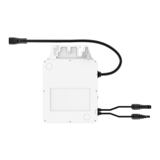
Product Overview 2.3.2 Dimensions 178 mm 34 mm Figure 2-3 Dimensions 2.3.3 Terminals of Microinverter Figure 2-4 Terminals of Microinverter... -
Page 18: Description Of Symbols
Product Overview Table 2-1 Description of terminals Item Description Spare ground For standby earth connection. cable clip AC terminal For AC connection. Indicator Show the status of the device. PV terminal For PV connection. A connection component for electrical devices which Earth lug need grounding (perferred grounding method). - Page 19 Product Overview Symbol Description Danger. Risk of electric shock! Danger to life due to high voltage. There is residual voltage in the microinverter which needs 5 min to discharge. • Wait for 5 min before you open the upper lid or the DC lid. Refer to the operating instructions.
-
Page 20: Preparation Before Installation
Preparation before Installation Unpacking and Inspection 3.1.1 Unpacking • The microinverter undergoes 100% testing and inspection before shipping from the manufacturing facility. However, transport damage may still occur. Before unpacking the Microinverter , please verify that the model and outer packing materials for damage, such as holes and cracks. -
Page 21: Packing Lists
Preparation before Installation Packing Lists Included in the box: Inverter × 1 Installation map × 1 Documents Sold separately: AC trunk port disconnect 1.2 m/ 1.6 m/ 2 m/ 2.4 m AC trunk end cap × 1 AC trunk connector × 1 tool ×... -
Page 22: Installation Angel Requirement
Preparation before Installation • Install the microinverter in a well-ventilated environment for heat dissipation; • Do not install the microinverter in areas with flammable, explosive and corrosive materials; • Do not install the microinverter in areas near combustibles and antennas; •... -
Page 23: Tools Requirement
Preparation before Installation Parallel to PV module Figure 3-1 Correct installation Tools Requirement 3.4.1 Recommended Equipment Installation tools include but are not limited to the following recommended ones. If necessary, use other auxiliary tools on site. Cable tie Multimeter Measuring tape Utility knife Torque screwdriver Marker... -
Page 24: Additional Required Material
Preparation before Installation Safety gloves Safety boots Safety goggles Anti-dust mask 3.4.2 Additional Required Material Table 3-4 Additional required material No. Required Material Requirements AC circuit breaker Current: 40 A for 10 AWG/32 A for 12 Guide rail At least two guid rails Sliding block Matching with the guide rail Screw... - Page 25 Preparation before Installation Maximum over A1-Micro 4500P A1-Micro 500P current protection device Maximum number per 10 AWG branch Maximum number per 12 AWG branch Maximum over current A1-Micro 600P protection device Maximum number per 10 AWG branch Maximum number per 12 AWG branch Note: An AC branch can connect to 1-in-1/2 in 1/4-in-1 microinverters at the same time, provided that the...
-
Page 26: Installation
Installation Accessories Figure 4-1 Accessories for single microinverter Figure 4-2 Other accessories for the whole system... -
Page 27: Microinverter Installation
Installation Description AC trunk cable PV cable AC trunk connector AC trunk end cap AC trunk port disconnect tool Female connector Male connector AC end cable NOTICE! • The above accessories are not included in the package and need to be purchased separately. - Page 28 Installation WARNING! • Pay attention to the earth lug. Risk of hand injury! Figure 4-4 Risk of hand injury Step 1: Rail Installation A) The installer has to install the rails on the roof and fix them with screws to ensure a stable installation environment for microinverters.
- Page 29 Installation C) Tighten the screws . 9±0.1 N·m NOTICE! • Choose the screwdriver according to the corresponding screws of the rail. Step 4: Place AC Trunk Cable on the Rail A) Place the AC trunk connector on the rail inwards (as shown below) and band it with cable ties.
- Page 30 Installation B ) Plug the male terminal of AC trunk cable into the female terminal of AC trunk connector. AC trunk cable Female Male C) Band the AC trunk cable with cable ties. In order to better fix the AC cable, it is recommended to use more cable ties to band the AC cable.
- Page 31 Installation E) Cover vacant AC ports with AC trunk end cap. Male Step 5: AC Trunk Cable Connection A) Plug the AC connector of the microinverter into the trunk cable connector. The connection is completed when you hear a "click". Click NOTICE! •...
- Page 32 Installation Step 7: Grounding methods We provide two grounding methods for this series of microinverters. If the earth lug doesn't touch the rail or the rail is not on the ground, please try method 2. Method 1 (major grounding method): Let the earth lug touch the rail. Let the earth lug touch the rail Method 2: Strip the PE cable, place the PE cable on the rail and fix it with screws.
- Page 33 Installation...
-
Page 34: Microinverter System Initiating
Installation Microinverter System Initiating 4.3.1 Initiate the System • Checking before Power-on » Check the device installed correctly and securely; » All AC cables are connected correctly and securely; » All DC cables are connected correctly and securely; » Make sure all photovoltaic panels are connected correctly and securely; »... -
Page 35: Setup Monitoring System
Scan the QR code to download SolaXCloud App. Step 2: Register an account and log in . XXXXXXXXX XXXXXXXXX NOTICE! • Before configurating network, please make sure that A1-Micro 1 in 1, ECC and ECC- PLC have been connected as a system. - Page 36 Installation Step 3: Add a site. XXXXXXX XXXXXXX XXXXXXX XXXXXXX NOTICE • Click the corresponding notice to know more details about how to Add Site. If you don't need reading these notices, click Skip.
- Page 37 Installation Step 4: Bind ECC in the added site. Step 5: Cofigurate network for ECC. xxxxxxxxxxxxxx xxxxxxxxxxxxxx XXXXXXXXXXXX...
- Page 38 Installation xxxxxxxx 是非成败转头 WIFI_XXXXXXX WIFI_XXXXXXX NOTICE • After ECC configuration succeeds, the connected ECC-PLC will show on the Gateway list. • Remember to switch to your home WiFi for the subsequent operation.
- Page 39 Installation Step 6: Enter the Device Detail interface, click Manage sub devices and collecting sub devices to bind A1-Micro 1 in 1.
- Page 40 Installation Step 7: After binding A1-Micro 1 in 1, click Chart to see more detail information. XXXXXXXXXXXXXX XXXXXXXXXXXXXX XXXXXXXXXXXXXX XXXXXXXXXXXXXX XXXXXXXXXXXXXX XXXXXXXXXXXX Step 8: Click Expand to check the data and graphics. XXXXXXXXXXXXX XXXXXXXXXXXXX XXXXXXXXXXXXX...
- Page 41 Installation Step 9: For advanced settings, please consult your distributor to get password.
-
Page 42: Troubleshooting And Maintenance
Troubleshooting and Maintenance LED Indicator Status Table 5-1 LED indicator status LED Indicator Status Description Microinverter startup. If the light flashes once in 1s, flashes in 10s or still flashes Yellow light flash after 10s, microinverter startup fails or DSP firmware is upgrading. Yellow light steady on Microinverter standby/self-checking. -
Page 43: Troubleshooting
Troubleshooting and Maintenance Troubleshooting This section contains information and procedures for resolving possible problems with the Microinverter , and provides the troubleshooting tips to identify and solve most problems that may occur. Please check the warning or fault information on the App and read the suggested solutions below when error occurs. - Page 44 Troubleshooting and Maintenance Code Faults Diagnosis and solutions Software Overcurrent Protection Fault. -Wait for a while to check if the microinverter is back to normal. IE0011 SW OCP Fault -Disconnect PV and grid, then reconnect. -Or seek help from us. Isolation Fault.
-
Page 45: On-Site Inspection (For Qualified Installer Only)
Troubleshooting and Maintenance On-Site Inspection (for qualified installer only) Follow the steps below to troubleshoot a malfunctioning microinverter. Step 1: Check the voltage and frequency of utility do not exceed the range described in Technical Data of this manual. Step 2: Check the connection to the utility grid. WARNING! •... -
Page 46: Maintenance Routines
Troubleshooting and Maintenance 5.4.1 Maintenance routines Item Check Notes Maintenance Inverval Safety check • Check the items mentioned in section 1 Every 12 months “Safety” • The safety check shall be performed by manufacturer’s qualified person who has adequate training, knowledge, and practical experience. - Page 47 Troubleshooting and Maintenance Upgrade steps Log into www.solaxcloud.com to upgrade the microinverter. Click Upgrade Firmware, Add, and fill in the information and upload firmware. Click Sure to finish firmware upgrade.
- Page 48 Troubleshooting and Maintenance Select Remote Upgrade, choose the microinverter you want to upgrade and click the upgrade icon. If you need batch upgrade, please select Equipment Classification, Applicable Model and Update program first. Then choose the models you want to upgrade, and click Batch Upgrade.
-
Page 49: Decommissioning
Decommissioning Disassembling the Microinverter To disassembling the microinverter » De-energize the AC breaker. » Dismount the PV module from the guide rail for meter detection. » Use a meter to check the DC cables and make sure no current flow exists in the wires between microinverter and module. -
Page 50: Transportation And Storage
Decommissioning Transportation and Storage If the microinverter is not put into use immediately, the transportation and storage requirements needs to be met: Transportation • Observe the caution signs on the packaging of microinverter before transportation. • Wear protective gloves when carrying the equipment by hand to prevent injuries. Storage •... -
Page 51: Technical Data
Technical Data • DC Input A1-Micro A1-Micro A1-Micro A1-Micro A1-Micro Model 300P 400P 450P 500P 600P Max. PV array input power 240 to 320 to 360 to 400 to 400 to [kWp] 410+ 550+ 600+ 670+ 670+ Max. PV voltage [d.c. V] MPPT voltage range [d.c. - Page 52 Technical Data • Efficiency, Standard and Environment limit A1-Micro A1-Micro A1-Micro A1-Micro A1-Micro Model 300P 400P 450P 500P 600P Peak efficiency [%] 96.50 CEC Eciency [%] 96.50 Nominal MPPT efficiency 99.50 Night power consumption < 63 [mW] UL 1741, UL 1741 SA, CSA C22.2 No.107.1-16, FCC Part 15 Compliance Class B, IEEE 1547, CA Rule 21 PV rapid shutdown...
-
Page 53: Appendix
Appendix INSTALLATION MAP... -
Page 54: Wiring Diagram -240Vac Split Phase
Appendix WIRING DIAGRAM –240VAC SPLIT PHASE:... -
Page 55: Wiring Diagram 240Vac Three-Phase
Appendix WIRING DIAGRAM 240Vac Three-Phase... -
Page 56: Minimum Measurement And Calculation Accuracy Requirements For Manufacturers
Appendix Minimum measurement and calculation accuracy requirements for manufacturers Time frame Steady-state measutements Minimum Measure-ment Parameter measurement Range window accuracy Voltage, (±1% Vnom) 10 cycles 0.5 p.u. to 1.2 pu Frequency 10 mHz 60 cycles 50 Hz to 66 Hz Active (±5% Srated) 10 cycles... -
Page 57: Voltage Trip Tests
Appendix Voltage Trip tests Low-Frequency ride-through tests&High-Frequency ride- through tests... -
Page 58: Frequency Trip
Appendix Frequency Trip... -
Page 59: P-Q
Appendix... - Page 60 Appendix...
-
Page 61: P-U
Appendix... - Page 62 Appendix...
-
Page 63: Constant Reactive Power
Appendix 8.10 Constant Reactive Power... -
Page 64: Volt-Var Mode
Appendix 8.11 Volt-Var Mode... -
Page 65: Prioritation
Appendix 8.12 Prioritation... - Page 66 Contact Information UNITED KINGDOM AUSTRALIA Unit C-D Riversdale House, Riversdale 21 Nicholas Dr, Dandenong South VIC 3175 Road, Atherstone, CV9 1FA +61 1300 476 529 +44 (0) 2476 586 998 service@solaxpower.com service.uk@solaxpower.com TURKEY GERMANY Fevzi Çakmak mah. aslım cd. no 88 A Am Tullnaupark 8, 90402 Nürnberg, Karatay / Konya / Türkiye Germany...
- Page 67 Warranty Registration Form For Customer (Compulsory) Name Country Phone Number Email Address State Zip Code Product Serial Number Date of Commissioning Installation Company Name Installer Name Electrician License No. For Installer Module ( If Any ) Module Brand Module Size(W) Number of String Number of Panel Per String Battery ( If Any )
- Page 68 EU member states. Safe distance warning Use the A1-Micro 1 in 1 in the environment with the temperature between -40°C to 70°C (-40°F to 158°F). The device complies with RF specifications when the device used at 20cm from your body.
- Page 69 E-mail: service.eu@solaxpower.com Tel: +31 (0)85 2737 932 SolaX Power Network Technology (Zhejiang) Co., Ltd. ADD.: No. 278, Shizhu Road, Chengnan Sub-district, Tonglu County, Hangzhou, Zhejiang, China E-mail: info@solaxpower.com www.solaxpower.com 320101099900 Copyright © SolaX Power Technology (Zhejiang) Co., Ltd. All rights reserved.
Need help?
Do you have a question about the A1-Micro 1 in 1 and is the answer not in the manual?
Questions and answers