Sign In
Upload
Download
Table of Contents
Contents
Add to my manuals
Delete from my manuals
Share
URL of this page:
HTML Link:
Bookmark this page
Add
Manual will be automatically added to "My Manuals"
Print this page
×
Bookmark added
×
Added to my manuals
Manuals
Brands
SeeedStudio Manuals
Controller
reComputer R1000
User manual
SeeedStudio reComputer R1000 User Manual
Edge iot controller
Hide thumbs
1
2
Table Of Contents
3
4
5
6
7
8
9
10
11
12
13
14
15
16
17
18
19
20
21
22
23
24
25
26
27
28
29
30
31
32
33
34
35
36
37
38
39
40
41
42
43
44
45
46
page
of
46
Go
/
46
Contents
Table of Contents
Bookmarks
Table of Contents
Revision History
Table of Contents
Contents
C1. Introduction
Overview
Feature
Specification
Dimension
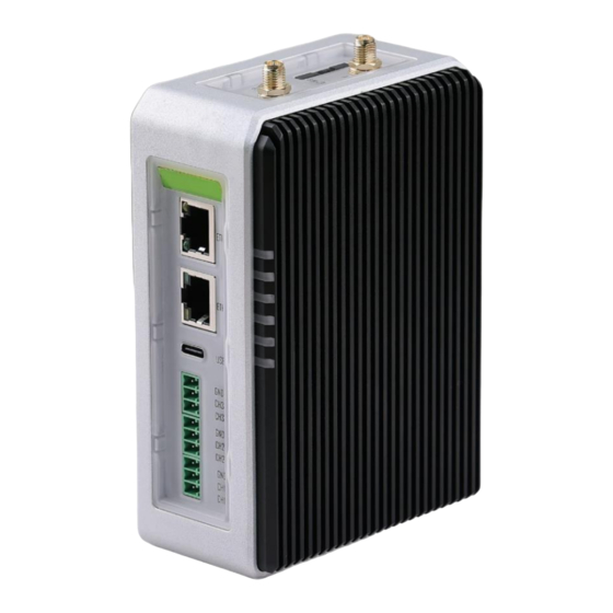
C2. Hardware Overview
System Overview
Interface Overview
Mainboard Overview
Power Diagram
Block Diagram
IIC Diagram
Interface Description
LED Indicator Status
Buzzer
Rs485
Boot Switch
Usb
SIM Slot
SSD Slot
Mini-Pcie Slot
Reset Hole
Ethernet RJ45
Hdmi
Rtc
Watchdog
Optional Interfaces and Module
Wi-Fi/Ble
Module
Lora® Module
Zigbee Module
Poe
Ssd
Encryption Chip TPM 2.0
Ups
Speaker
C3. Configuring System
Flashing Image
Query GPIO Mappings
GPIO Testing
SPI Communication Testing
Wi-Fi Scanning
Bluetooth Scanning
Lora ® over Mini-Pcie
Lora ® SPI
Lora ® USB
Cellular over Mini-Pcie
Zigbee over Mini-Pcie
RS485 Drivers
USB Hub Testing
MAC Address of Ethernet
Rtc
Watchdog
Buzzer
Speaker
Tpm 2.0
Atecc608A
Eeprom
Ssd
UPS for Safe Shut down
Installing Ubuntu on Recomputer R1000
Customized Linux: Yocto and Mender
Costomized Linux: Buildroot
C4. Assembly Guide
Disassembly Guide
Assemble SSD
Assemble Wi-Fi/Ble Antenna
Assemble 4G/Lora®/Zigbee Module and Antenna
Assemble TPM 2.0 Module
Assemble UPS and Poe Module
Mounting Guide
DIN-Rail Mounting Guide
Wall Mounting Guide
C5. Accessories List
C6. Warranty & Support
Warranty
Support
Advertisement
Quick Links
Download this manual
Table of
Contents
Previous
Page
Next
Page
1
2
3
4
5
Advertisement
Table of Contents
Need help?
Do you have a question about the reComputer R1000 and is the answer not in the manual?
Ask a question
Questions and answers
Related Manuals for SeeedStudio reComputer R1000
Controller SeeedStudio reComputer R1025-10 User Manual
Edge iot controller (46 pages)
Controller SeeedStudio CAN-BUS Shield V1.2 Manual
(14 pages)
Controller SeeedStudio EdgeBox-RPI-200 User Manual
Raspberry pi cm4 based edge computer (28 pages)
Controller SeeedStudio EdgeBox-RPI-200 User Manual
V1.0 raspberry pi cm4 based edge computer (25 pages)
This manual is also suitable for:
Recomputer r1035-10
Recomputer r1025-10
Recomputer r1024-10
Recomputer r1013-10
E24010521
113991314
...
Show all
113991274
113991294
113991295
Table of Contents
Print
Rename the bookmark
Delete bookmark?
Delete from my manuals?
Login
Sign In
OR
Sign in with Facebook
Sign in with Google
Upload manual
Upload from disk
Upload from URL


Need help?
Do you have a question about the reComputer R1000 and is the answer not in the manual?
Questions and answers