
Related Manuals for SeeedStudio EdgeBox-RPI-200


Summary of Contents for SeeedStudio EdgeBox-RPI-200
- Page 1 EdgeBox-RPI-200 User Manual — — — — — — — — — — — — — — — — — — — — — — — — — — — — — — — — — — — — —...
- Page 2 EdgeBox-RPI-200 User Manual Revision History Changes Revision Date...
-
Page 3: Table Of Contents
EdgeBox-RPI-200 User Manual Contents 1. Introduction ......................................4 1. 1 Features ......................................4 1.2 Interfaces ...................................... 5 1.3 Block Diagram .................................... 7 2. Installation ......................................8 2. 1 Mounting ...................................... 8 2.2 Connectors and Interfaces ................................9 2.2. 1 Power supply ................................... 9 2.2.2 Serial Port (RS232 and RS485) ............................ -
Page 4: Introduction
EdgeBox-RPI-200 User Manual 1. Introduction 1.1 Features... -
Page 5: Interfaces
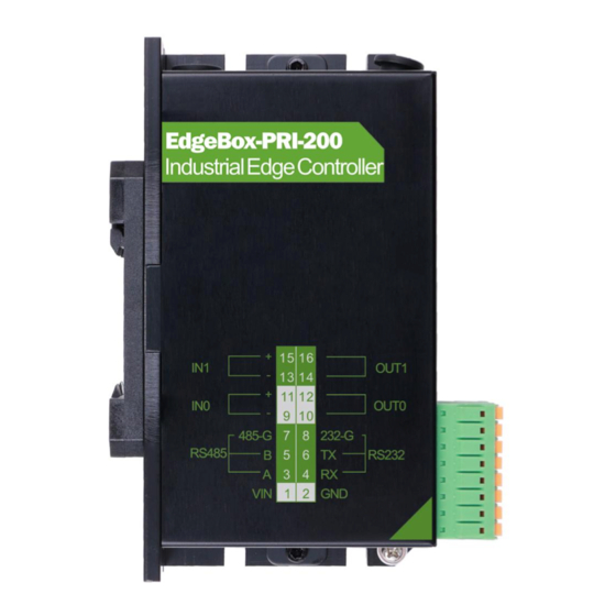
EdgeBox-RPI-200 User Manual 1.2 Interfaces Note Func name PIN # PIN# Func name Note... - Page 6 EdgeBox-RPI-200 User Manual NOTE:...
-
Page 7: Block Diagram
EdgeBox-RPI-200 User Manual 1.3 Block Diagram... -
Page 8: Installation
EdgeBox-RPI-200 User Manual 2. Installation 2.1 Mounting... -
Page 9: Connectors And Interfaces
EdgeBox-RPI-200 User Manual 2.2 Connectors and Interfaces 2.2.1 Power supply Signal Description Pin# 2.2.2 Serial Port (RS232 and RS485) Signal Description Pin#... -
Page 10: Di&Do
EdgeBox-RPI-200 User Manual Signal Description Pin# NOTE: 2.2.3 DI&DO Signal of Pin# PIN Level PIN of GPIO NOTE terminal from active BCM2711 NOTE:... -
Page 11: Hdmi
EdgeBox-RPI-200 User Manual NOTE: 2.2.4 HDMI Directly connected to the Raspberry PI CM4 board with TVS array. 2.2.5 Ethernet Ethernet interface is same as Raspberry PI CM4 , 1 0 / 1 0 0 / 1 0 0 0 - BaseT supported, available through the... -
Page 12: Usb Host
EdgeBox-RPI-200 User Manual 2.2.6 USB HOST NOTE: 2.2.7 Console(USB typeC) 2.2.8 LED LED1 LED2... - Page 13 EdgeBox-RPI-200 User Manual...
-
Page 14: Sma Connector
EdgeBox-RPI-200 User Manual 2.2.9 SMA Connector NOTES: 2.2.10 NANO SIM card slot... -
Page 15: Mini-Pcie
EdgeBox-RPI-200 User Manual NOTES: 2.2.11 Mini-PCIe The table below show all the signals. Full size Mini- PCIe card are supported. Signal Signal PIN# PIN# USIM_ PWR USIM_ PWR USIM_ DATA USIM_ CLK USIM_RESET#... - Page 16 EdgeBox-RPI-200 User Manual PERST# 4G_PWR UART_PCIE_TX UART_PCIE_RX USB_ DM 4G_PWR 4G_ LED USIM_ DET SPI1_SCK SPI1_ MISO SPI1_ MOSI SPI1_SS 4G_ PWR NOTE 1: NOTE 2 : NR3015T2R2M 4 G_ PWR ind_lps3015 10uF SY8089 C0603 sot_23_5 VCC_ 3V3 18pF R0402...
-
Page 17: Drivers And Programming Interfaces
EdgeBox-RPI-200 User Manual 3. Drivers and Programming Interfaces 3.1 LED... -
Page 18: Serial Port (Rs232 And Rs485)
EdgeBox-RPI-200 User Manual Serial Port (RS232 and RS485) 3.3 Cellular over Mini-PCIe Insert the EC20 into Mini-PCIe socket and micro sim card in related slot, connect the antenna. Log in the system via console use pi/raspberry. Turn on the power of Mini-PCIe socket and release the reset signal. - Page 19 EdgeBox-RPI-200 User Manual How to use AT command...
- Page 20 EdgeBox-RPI-200 User Manual...
- Page 21 EdgeBox-RPI-200 User Manual How to dial Add the router path...
-
Page 22: Wdt
EdgeBox-RPI-200 User Manual 3.4 WDT 3.4.1 Block Diagram of WDT The WDT module have three terminals, input , output and LED indicator. LED GREEN Note: 3.4.2 How it works 3.5 RTC 3.5.1... -
Page 23: Ups For Safe Shut Down
EdgeBox-RPI-200 User Manual 3.5.2 Note 3.10 UPS for safe shut down... - Page 24 EdgeBox-RPI-200 User Manual NOTE:...
-
Page 25: Electrical Specifications
EdgeBox-RPI-200 User Manual 4. Electrical specifications Power consumption Note: Mode of Current(ma) Power Remark operation backup time of UPS module is very depend on the system load of the system. Some typical conditions are listed below. The test module of CM4 is 4GB LPDDR4,32GB eMMC with Wi- FI module.
Need help?
Do you have a question about the EdgeBox-RPI-200 and is the answer not in the manual?
Questions and answers