Advertisement
Quick Links
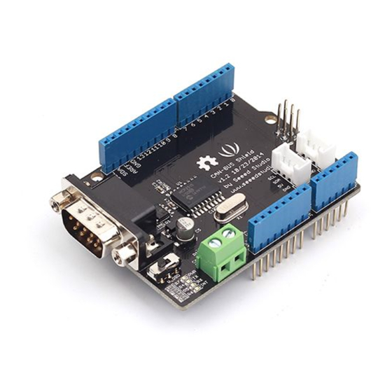
CAN-BUS Shield V1.2
Introduction
CAN-BUS is a common industrial bus because of its long travel distance, medium
communication speed and high reliability. It is commonly found on modern machine
tools and as an automotive diagnostic bus.
This CAN-BUS Shield adopts MCP2515 CAN Bus controller with SPI interface
and MCP2551CAN transceiver to give your Arduino/Seeeduino CAN-BUS capability.
With an OBD-IIconverter cable added on and the OBD-II library imported, you are
ready to build an onboard diagnostic device or data logger.
Version
This document applies to the following version of products:
What's new in CAN BUS Shield V1.2 Pads on the back of PCBA Change terminal
resistor to 120 Ohm
Advertisement

Related Manuals for SeeedStudio CAN-BUS Shield V1.2


Summary of Contents for SeeedStudio CAN-BUS Shield V1.2
- Page 1 CAN-BUS Shield V1.2 Introduction CAN-BUS is a common industrial bus because of its long travel distance, medium communication speed and high reliability. It is commonly found on modern machine tools and as an automotive diagnostic bus. This CAN-BUS Shield adopts MCP2515 CAN Bus controller with SPI interface and MCP2551CAN transceiver to give your Arduino/Seeeduino CAN-BUS capability.
-
Page 2: Hardware Overview
Features • Implements CAN V2.0B at up to 1 Mb/s • SPI Interface up to 10 MHz • Standard (11 bit) and extended (29 bit) data and remote frames • Two receive buffers with prioritized message storage • Industrial standard DB-9 connector •... - Page 3 1. DB9 Interface - to connect to OBDII Interface via a DBG-OBD Cable. 2. V_OBD - If get power from OBDII Interface (from DB9) 3. Led Indicator: • PWR: power • TX: blink when the data is sending • RX: blink when there’s data coming •...
- Page 4 Note The pin FREE is available for the other usages. DB9&OBDii Interface CS pin SPI_CS pin of V1.2 is default to D9. If you want to change it to D10. • Step1: Take a look at the back of the PCBA, you will find a pad named CS.
- Page 5 • Step2: Cut the wire that connect pad9 and the middle pad • Step3:Solder the middle pad and pad 10.
-
Page 6: Getting Started
Warning Be careful with the box cutter, it’s easy to hurt yourself or the PCBA. SPI pins The SPI pins (SCK, MISO, MOSI) is default to the ICSP pins. But for some Boards, maybe the SPI pins is at D11~D13, if so you need to change something in the PCBA. Take a look that the back of the PCBA, there’re three pads, MOSI, MISO and SCK, they are default to A. - Page 7 STEP2: Hardware Connection Insert each CAN-BUS Shield to Seeeduino V4.2, and connect the 2 CAN-BUS Shield together via 2 jumper wires. Shown as below images. Note CAN_H to CAN_H, CAN_L to CAN_L STEP3: Software Click on the below button to download the library. Install the library to your Arduino IDE when it is downloaded.
- Page 8 Note Each node can act at master before the code is uploaded. Open the send example (File > Examples > CAN_BUS_Shield-master > send) and upload to the master. Open the receive_check example (File > Examples > CAN_BUS_Shield-master > receive_check) and upload to the slaver. STEP4: View Result Open the Serial Monitor of Arduino IDE(slaver), you will get the data sent from the master.
- Page 9 APIs 1. Set the Baud rate This function is used to initialize the baud rate of the CAN Bus system. The available baud rates are listed as follows: #define CAN_5KBPS #define CAN_10KBPS #define CAN_20KBPS #define CAN_25KBPS #define CAN_31K25BPS 5 #define CAN_33KBPS #define CAN_40KBPS #define CAN_50KBPS #define CAN_80KBPS...
- Page 10 We provide two functions for you to utilize these mask and filter registers. They are: Mask: init_Mask(unsigned char num, unsigned char ext, unsigned char ulData); Filter: init_Filt(unsigned char num, unsigned char ext, unsigned char ulData); • num represents which register to use. You can fill 0 or 1 for mask and 0 to 5 for filter. •...
-
Page 11: Receive Data
• len represents the length of this frame. • data_buf is the content of this message. For example, In the ‘send’ example, we have: unsigned char stmp[8] = {0, 1, 2, 3, 4, 5, 6, 7}; CAN.sendMsgBuf(0x00, 0, 8, stmp); //send out the message 'stmp' to the bus and tell other devices this is a standard frame from 0x00. - Page 12 #define CAN_125KBPS #define CAN_200KBPS #define CAN_250KBPS #define CAN_500KBPS #define CAN_666kbps #define CAN_1000KBPS 18 Yet you may still can’t find the rate you want. Here we provide a software to help you to calculate the baud rate you need. Click here to download the software, it’s in Chinese, but never mind, it’s easy to use.
- Page 13 You need to add some code to the library. Open mcp_can_dfs.h, you need to add some code at about line 272: #define MCP_16MHz_xxxkBPS_CFG1 (cfg1) // xxx is the baud rate you need #define MCP_16MHz_xxxkBPS_CFG2 (cfg2) #define MCP_16MHz_xxxkBPS_CFG3 (cfg2) Then let’s go to about line 390, add some code: #define CAN_xxxKBPS NUM // xxx is the baudrate you need, and NUM is a number, you need to get a different from the other rates.
- Page 14 Volkswagen CAN BUS Gaming Ever wanted to play a car/truck simulator with a real dashboard on your PC? Me too! I’m trying to control a VW Polo 6R dashboard via CAN Bus with an Arduino Uno and a Seeed CAN Bus Shield. Inspired by Silas Parker. Thanks to Sepp and Is0-Mick for their great support!
Need help?
Do you have a question about the CAN-BUS Shield V1.2 and is the answer not in the manual?
Questions and answers