Table of Contents
Advertisement
Quick Links
Advertisement
Table of Contents

Related Manuals for SeeedStudio EdgeBox-RPI-200


Summary of Contents for SeeedStudio EdgeBox-RPI-200
- Page 1 ——————————————————————————————————————————— ——————————————————————————————————————————— EdgeBox-RPI-200 User Manual V2.1 Raspberry PI CM4 Based Edge computer Revision History Revision Date Changes 17-08-2022 Created 13-01-2022 Product Change Notice...
- Page 2 EdgeBox-RPI-200 User Manual Product Change Notice: As a part of our continual improvement process, we made the below changes in hardware version There is impact on the software due to this change. CP2104->CH9102F USB2514B->CH334U CP2105->CH342F The description in the Linux have been changed: ttyUSB0->...
-
Page 3: Table Of Contents
EdgeBox-RPI-200 User Manual Contents Introduction ..........................1 Features .......................... 1 Interfaces ......................... 2 1.2.1 Multi-Func phoenix connector ..................3 Block Diagram ......................... 4 Installation ..........................5 Mounting .......................... 5 Connectors and Interfaces ....................6 2.2.1 Power supply ........................ 6 2.2.2 Serial Port (RS232 and RS485) ................... - Page 4 EdgeBox-RPI-200 User Manual 3.5.2 Enable RTC ........................ 21 UPS for safe shut down (Optional) ................23 Electrical specifications ......................24 Power consumption ....................... 24 UPS ..........................24 Mechanical Drawings ....................... 24...
-
Page 5: Introduction
EdgeBox-RPI-200 User Manual 1 Introduction EdgeBox-RPI-200 is a rugged fan less Edge Computing Controller with Raspberry Pi Computer Module 4(CM4) for harsh industry environment. It can be used to connect the field networks with cloud or IoT applications. It is designed from the ground up to meet the challenges of rugged applications at competitive prices, ideal for small business or small order with scale multi-level demands. -
Page 6: Interfaces
EdgeBox-RPI-200 User Manual 1.2 Interfaces ① Multi-Func phoenix connector ② Ethernet connector ③ USB 2.0 x 2 ④ HDMI ⑤ LED2 ⑥ LED1 ⑦ SMA antenna 1 ⑧ Console (USB type C) ⑨ SIM card slot ⑩ SMA antenna 2... -
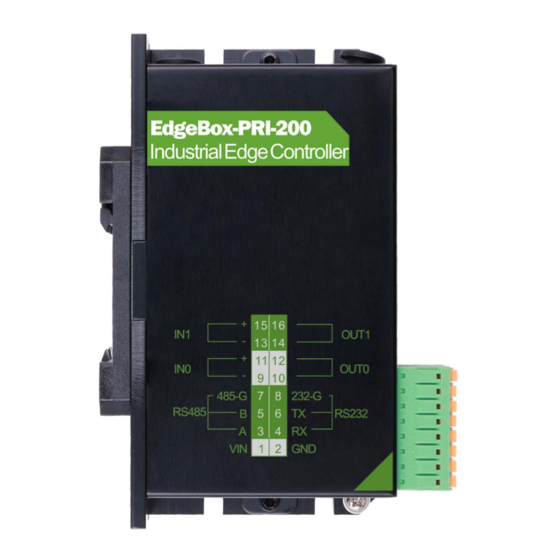
Page 7: Multi-Func Phoenix Connector
EdgeBox-RPI-200 User Manual 1.2.1 Multi-Func phoenix connector Note Func name PIN # PIN# Func name Note POWER RS485_A RS232_RX RS485_B RS232_TX RS485_GND RS232_GND DI0- DO0_0 DI0+ DO0_1 DI1- DO1_0 DI1+ DO1_1 NOTE: 24awg to 16awg cable are suggested WWW.SEEEDSTUDIO.COM... -
Page 8: Block Diagram
EdgeBox-RPI-200 User Manual 1.3 Block Diagram The processing core of the EdgeBox-RPI-200 is a Raspberry CM4 board. A specific base board implements the specific features. Refer to next figure for the block diagram. WWW.SEEEDSTUDIO.COM... -
Page 9: Installation
EdgeBox-RPI-200 User Manual 2 Installation 2.1 Mounting The EdgeBox-RPI-200 is intended for two wall mounts, as well one with 35mm DIN-rail. Refer to next figure for the recommended mounting orientation. WWW.SEEEDSTUDIO.COM... -
Page 10: Connectors And Interfaces
EdgeBox-RPI-200 User Manual 2.2 Connectors and Interfaces 2.2.1 Power supply Pin# Signal Description POWER_IN DC 9-36V Ground (Reference potential) The PE signal is optional. If there is no EMI present, the PE connection can leave open. WWW.SEEEDSTUDIO.COM... -
Page 11: Serial Port (Rs232 And Rs485)
EdgeBox-RPI-200 User Manual 2.2.2 Serial Port (RS232 and RS485) Pin# Signal Description RS232_RX RS232 receive line RS232_TX RS232 transmit line Ground (Reference potential) Pin# Signal Description RS485_A RS485 difference line high RS485_B RS485 difference line low RS485 _GND RS485 Ground (isolated from GND) The RS485_GND signal is isolated with “GND”... -
Page 12: Di&Do
EdgeBox-RPI-200 User Manual 2.2.3 DI&DO Pin# Signal of PIN Level PIN of GPIO from NOTE terminal of active BCM2711 DI0- HIGH GPIO17 DI0+ DI1- HIGH GPIO27 DI1+ DO0_0 HIGH GPIO23 DO0_1 DO1_0 HIGH GPIO24 DO1_1 NOTE: WWW.SEEEDSTUDIO.COM... -
Page 13: Hdmi
EdgeBox-RPI-200 User Manual NOTE: DC voltage for input is 24V (+- 10%). DC voltage for output should be under 60V, the current capacity is 500ma. Channel 0 and channel 1 of input are isolated to each other Channel 0 and channel 1 of output are isolated to each other 2.2.4 HDMI... -
Page 14: Led
EdgeBox-RPI-200 User Manual 2.2.8 LED EdgeBox-RPI-200 use two green/red dual colour LED as outside indicators. LED1: green as power indicator and red as eMMC active. LED2: green as 4G indicator and red as user programmable led connected to GPIO21, low active, programmable. -
Page 15: Sma Connector
EdgeBox-RPI-200 User Manual 2.2.9 SMA Connector There are two SMA Connector holes for antennas. The antenna types are very depended on what modules fitted into the Mini-PCIe socket. The ANT1 is default used for Mini-PCIe socket and ANT2 is for Internal WI-FI signal from CM4 module. -
Page 16: Mini-Pcie
EdgeBox-RPI-200 User Manual Mini-PCIe 2.2.11 The orange area is the rough Mini-PCIe add-on card position, only one m2x5 screw is needed. The table below show all the signals. Full size Mini-PCIe card are supported. WWW.SEEEDSTUDIO.COM... - Page 17 EdgeBox-RPI-200 User Manual Pinout: Signal PIN# PIN# Signal 4G_PWR USIM_PWR USIM_PWR USIM_DATA USIM_CLK USIM_RESET# PERST# 4G_PWR UART_PCIE_TX UART_PCIE_RX USB_DM USB_DP 4G_PWR 4G_PWR 4G_LED USIM_DET SPI1_SCK SPI1_MISO SPI1_MOSI SPI1_SS 4G_PWR WWW.SEEEDSTUDIO.COM...
- Page 18 4G_LED signal is connected to LED2 internally, refer to section of 2.2.8. SPI1 signals are used only for LoraWAN card, such as WM1302. 2.2.12 EdgeBox-RPI-200 equipped a M.2 socket of M KEY type. ONLY 2242 size NVME SSD card is support, NOT mSATA. WWW.SEEEDSTUDIO.COM...
-
Page 19: Drivers And Programming Interfaces
EdgeBox-RPI-200 User Manual 3 Drivers and Programming Interfaces 3.1 LED The is a LED used as user indicator, refer to 2.2.8. Use LED2 as a example to test the function. $ sudo -i #enable root account privileges $ cd /sys/class/gpio $ echo 21 >... - Page 20 EdgeBox-RPI-200 User Manual antenna. 2. Log in the system via console use pi/raspberry. 3. Turn on the power of Mini-PCIe socket and release the reset signal. $ sudo -i #enable root account privileges $ cd /sys/class/gpio $ echo 6 > export #GPIO6 which is POW_ON signal $ echo 5 >...
- Page 21 EdgeBox-RPI-200 User Manual [ 185.666283] usb 1-1.3: GSM modem (1-port) converter now attached to ttyUSB2 [ 185.666499] option 1-1.3:1.1: GSM modem (1-port) converter detected [ 185.666701] usb 1-1.3: GSM modem (1-port) converter now attached to ttyUSB3 [ 185.666880] option 1-1.3:1.2: GSM modem (1-port) converter detected [ 185.667048] usb 1-1.3: GSM modem (1-port) converter now attached to ttyUSB4...
- Page 22 EdgeBox-RPI-200 User Manual --- 7: /dev/ttyUSB3 'Android' --- Enter port index or full name: $ miniterm /dev/ttyUSB5 115200 Some useful AT command: ⚫ AT //should return OK ⚫ AT+QINISTAT //return the initialization status of (U)SIM card, the response should be 7 ⚫...
-
Page 23: Wdt
EdgeBox-RPI-200 User Manual 7. Add the router path $ route add default gw 10.64.64.64 or your gateway XX.XX.XX.XX Then have a test with ping: $ ping google.com 3.4 WDT 3.4.1 Block Diagram of WDT The WDT module have three terminals, input, output and LED indicator. - Page 24 EdgeBox-RPI-200 User Manual every 2 seconds, if not, the WDT module should output a negative pulse to reset the system. 9. Goto 2. WWW.SEEEDSTUDIO.COM...
-
Page 25: Rtc
EdgeBox-RPI-200 User Manual 3.5 RTC 3.5.1 RTC Chip information New Revision: The chip of RTC is PCF8563 from NXP. It is mounted on the system I2C bus, the i2c address should be 0x51. GPIO2 I2C_SDA R0402 GPIO3 I2C_SCL R0402 The OS itself has the driver inside, only we need are some configurations. - Page 26 EdgeBox-RPI-200 User Manual NOTE: make sure the i2c-1 driver point is open, and the point is closed default. the estimated backup time of the RTC is 15 days. Product Change NOTE: OLD Revision: The chip of RTC is MCP79410 from microchip. It is mounted on the system I2C bus.
-
Page 27: Ups For Safe Shut Down (Optional)
EdgeBox-RPI-200 User Manual 3.6 UPS for safe shut down (Optional) The UPS module diagram is listed below. The UPS module is inserted between the DC5V and CM4, a GPIO is used to alarm CPU when the 5V power supply is down. Then the CPU should do something urgent in a script before energy exhaustion of super capacitor and run a “$ shutdown”... -
Page 28: Electrical Specifications
EdgeBox-RPI-200 User Manual 4 Electrical specifications 4.1 Power consumption The power consumption of the EdgeBox-RPI-200 strongly depends on the application, the mode of operation and the peripheral devices connected. The given values have to be seen as approximate values. The following table shows power consumption parameters of the EdgeBox-RPI-200: Note: On condition of power supply 24V, no add-on card in sockets and no USB devices.
Need help?
Do you have a question about the EdgeBox-RPI-200 and is the answer not in the manual?
Questions and answers