Table of Contents
Advertisement
Quick Links
Advertisement
Table of Contents

Subscribe to Our Youtube Channel
Related Manuals for RS RM-1500


Summary of Contents for RS RM-1500
- Page 1 DIGITAL PHOTO TACHOMETER MODEL: RM-1500/1501/1502 INSTRUCTION MANUAL...
-
Page 2: Table Of Contents
3.9. Using the MAX/MIN/AVE Function ............. 10 3.10. Turning On/Off Tachometer.............. 11 3.11. Disable Auto-Power-Off Function ............. 11 3.12. REPLACING THE BATTERIES ............12 4. Protocol of RS-232C Serial Interface (RM-1501)........13 5. Installation of Window Application Software (RM-1501) ......14 6. Description of Windows... -
Page 3: Specifications
1. SPECIFICATIONS Speed (Non-contact): Range Resolution Accuracy 10.00 - 99999 0.01/0.1/1 0.04% ±2 dgts rps(Hz) 0.200 - 2000.0 0.001/0.01/0.1 0.04% ±2 dgts Speed (Contact) Range Resolution Accuracy RPM / (/ 20.00 - 29999 0.01/0.1/1 0.04% ±2 dgts symoblizes "Contact" m/min 2.000 - 2999.9 0.001/0.01/0.1 0.04% ±2 dgts... -
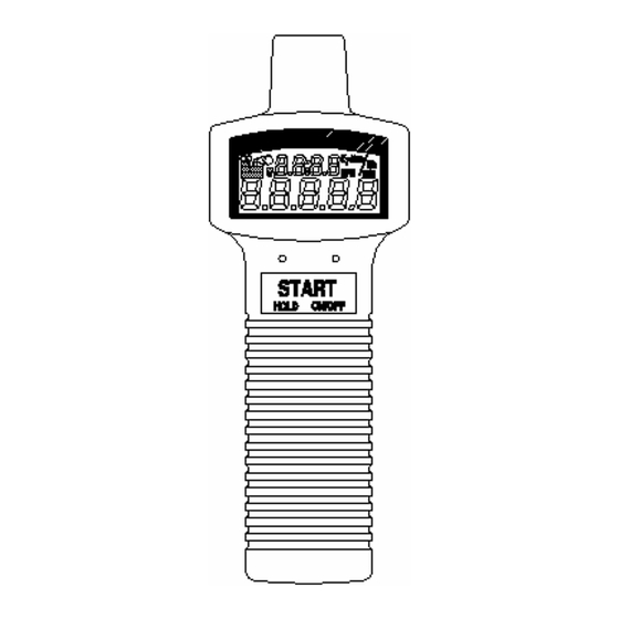
Page 4: Panel Functions
2. PANEL FUNCTIONS 2.11 2.10... - Page 5 2.1. Reflecting tape Attach a reflecting tape to the surface of the unit to be measured 2.2. Reflecting signal light beam It is recommenced that the reflecting surface is perpendicular to the emitting/receiving unit for best measurement. 2.3. Emitting/Receiving Unit The red light emits from the left side of the tachometer.
-
Page 6: Operating Instruction
3. OPERATING INSTRUCTION... -
Page 7: Normal Operation
3.1. Normal Operation a. Install four 1.5V AA size batteries. b. Cut off a piece of reflective tape of size 1.0 cm x 1.4 cm (optimal size) c. Wipe off oil or stains from the surface where reflective tape will be adhered. -
Page 8: Using The Mechanical Adaptor (Option Rm1502)
3.2. Using the Mechanical Adaptor (Option RM1502) a. Select proper rubber head. b. Attach the mechanical adaptor to the unit.and fasten the screw. c. Press the unit button (left button) to select RPM / ( instead of RPM only). The auxiliary LED will be turned on while the main LED will be turned off. -
Page 9: Measurement Of Surface Speed(M/Min, Ft/Min, Or Yd/Min)
3.3. Measurement of Surface Speed(m/min, ft/min, or yd/min) a. Attach the mechanical adaptor (option RM-1502) to the unit. b. Press the unit button to select desired unit. The auxiliary LED will be turned on while the main LED will be turned off. c. -
Page 10: Use As An Event Counter With External Light Source
3.4. Use as an Event Counter with External Light Source a. Press the unit button several times to select the unit of "No. O" (counts). The "O" symbol is used to instruct users that external light source is required. b. When the symbol "No. O" appears, the tachometer reset the upper clock to 00:00 and start counting the pulses it detects. -
Page 11: Digital Pulse Signal Output (Rm1501)
NOTE: It is strongly recommended that the emiting/receiving unit be covered to avoid undesired light signal coming in. 3.7. Digital Pulse Signal Output (RM1501) Users can output digital pulse signal through pin 8 of RS232C connector with pin 5 as signal ground to oscilloscope. 3.8. -
Page 12: Using The Max/Min/Ave Function
Correct RPM = Reading / (number of pieces of tape) Example: 4 pieces of tape and reading is 12 RPM. Correct Speed = 12 / 4 = 3 rpm 3.9. Using the MAX/MIN/AVE Functions These functions allow users to analyze the stability of rotational speed. These value are actually peak (MAX), valley(MIN), and true average(AVE) values. -
Page 13: Replacing The Batteries
3.12. REPLACING THE BATTERIES When symbol (low battery) appears in the LCD, it is time to replace the batteries. Remove the screw of the battery cover and remove the battery cover. Replace the old batteries with 4 new batteries. Do not mix different type of batteries together. -
Page 14: Protocol Of Rs-232C Serial Interface (Rm-1501)
4. Protocol of RS-232C Serial Interface (RM-1501) Ten bytes are sent out through RS-232C connector to PC. The definitions of each byte are as followings: Byte 1: Leading byte 0x0D Byte 2: Decimal point of LCD display bit0: dp1 (0000.0), if 1 bit1: dp2 (000.00), if 1... -
Page 15: Installation Of Window Tm Application Software (Rm-1501)
5. Installation of Window Application Software (RM-1501) 5.1. For Windows 3.1 A. Start Microsoft Windows B. Insert disk in drive A (or B) C. From Program Manager, select File menu and choose Run D. Type a:\setup (or b:\setup) and press Enter key 5.2. -
Page 16: Description Of Windows Tm Application Program (Rm-1501)
6. Description of Windows Application Program (RM-1501) Main Window: When the program is executed, the program automatically search for connected tachometer or available serial port. If no serial port is available, then a message of "No communication port" will be displayed, and the program exits . Once communication port is setup, a main window will be displayed on the screen as below: Sample:... - Page 17 If the View option under FILE in the Main Window is selected, a view window will be shown as above, and the users can review your ASCII data file. If a printer is connected to the PC, users can print out content selectively. File: Open users data file by selecting this menu.
- Page 18 Plotting Data from File If the "Plot Data from File" option under FILE is selected in the Main Window, a Plot Window will be shown, and the users can plot curve of your data file. If a printer is connected, users can print out the curve. File: Open the file to plot data from Scale:...
- Page 19 DISPLAY: DISPLAY menu has four options: DIGITAL, ANALOG, LIST, and GRAPHIC. DIGITAL: If this option is selected or CTRL+D is pressed, a window, which emulates multimeter's LCD display, shall appears on the screen. ANALOG: If this option is selected or CTRL+A is pressed, a window, which emulates an analog meter, shall appear on the screen.
- Page 20 LIST: If this option is selected or CTRL+L is pressed, a window, which lists the date, function, range, and value every sampling, shall appear on the screen. GRAPHIC: If this option is selected or CTRL+G is pressed, a window, which emulates strip chart recorder, shall appear on the screen.
- Page 21 Option: If you select Option, a pull down menu will show three options: Sample Rate, Baud Rate. Upper Limit: Enter upper limit. If upper limit is exceeded, a OVER message will be displayed in screen. Lower Limit: Enter lower limit. If displayed value is less than lower limit, a UNDER message will be displayed in screen.
Need help?
Do you have a question about the RM-1500 and is the answer not in the manual?
Questions and answers