Table of Contents
Advertisement
Quick Links
Vestfrost Solutions is working towards reaching the UN - Global Sustainable
Development Goals by 2030.
The Sustainable Development Goals are the blueprint to achieve a better and
more sustainable future for all.
In order to implement Goal no 12 "Responsible Consumption and Production",
this manual has been printed on recycled paper.
Technical manual VLS 076 RF SDD
Advertisement
Table of Contents

Related Manuals for Vestfrost VLS 076 RF SDD


Summary of Contents for Vestfrost VLS 076 RF SDD
- Page 1 Vestfrost Solutions is working towards reaching the UN - Global Sustainable Development Goals by 2030. The Sustainable Development Goals are the blueprint to achieve a better and more sustainable future for all. In order to implement Goal no 12 ”Responsible Consumption and Production”, this manual has been printed on recycled paper.
-
Page 2: Warning
WARNING WARNING: As the appliance contains flam- mable refrigerant, as stated Do not damage the refrigerant on nameplate, it is essential to system. ensure that the refrigerant pipes WARNING: are not damaged. The appliance may not be The quantity and type of the exposed to rain. - Page 3 WARNING: WARNING: Always, keep the keys in a Do not locate multiple portable separate place and out of reach socket-outlets or portable power of children. supplies at the rear of the appliance. WARNING: Before servicing or cleaning WARNING: the appliance, switch off circuit Appliance use flammable insula- breaker.
-
Page 4: Table Of Contents
Freezer Thermostat Replacement ...28 Freezer fuse replacement ......30 Compressor replacement ......31 Trouble shooting ........32 Technical support ........33 Recycling procedures .......34 PQS Code Model PQS Performance PQS Independent specifications type-testing protocol Specification reference: Product verification protocol: VLS 076 RF SDD E003/119 E003/RF05.4 E003/RF05-VP.4... -
Page 5: Periodic Preventive Maintenance Checks
Periodic preventive maintenance checks Daily Check: Monitor Temperature Internal lid is placed properly Lid fits and lock tight to cabinet Lid gasket not faulty. Condensation build up in vaccine compart- ment. Weekly maintenance: Remove any water at the bottom of the refrigerator with a cloth. -
Page 6: Complete Spare Part List Vls 076A Ac
Complete spare part list VLS 076A AC VLS 076 RF SDD Position Item number Item name 0061 0-6538001 Filter drier, 0087 0-6038175 Base plate fittings, complete 0129 8-036510223 Compressor - BD35K 101Z0211 10-45V - ECU 6520845 2170 0-A9301260103 Distance piece... - Page 7 5603 � 606 5705 2431 . � ✓ 5682 � --------------------- ------------ ------7------------- 5052 < 5963 � 5052 5570 2170 � 1 - R077 Version B - 19.05.2022...
-
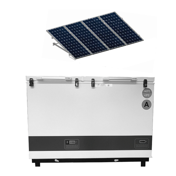
Page 8: Vital Components
Vital components Position Item no Description 0129 8-036510223 Compressor 5712 702090043 Safety thermostat 5712 702090044 Thermostat 5727 6520845 Starting Device ECU PV Solar Panel Kit 2x180W... -
Page 9: Health And Safety Guidance - Warning
Health and safety guidance – Warning! Before any repair job be aware of following! WARNING: Before servicing or cleaning the appliance, disconnect it from power source. WARNING: Danger risk of fire or explosion. Flammable refrigerant used. To be repaired only by trained personnel. -
Page 10: Required Basic Tools
Required basic tools 1.Flexible socket wrench - size 7+13mm 2.Nose plier 3.Screwdriver - size 1,0x6,0 + 0,6x3,5 4.Phillips screwdriver 5.Torx screwdriver - size T10 + T20 6.Clamp meter 7.Multimeter Proposed additional service kit/items Sealing kit Tar tape Extra self-tapping screws... -
Page 11: Motor Compartment
Motor compartment How to get access to the motor compartment. Use a screwdriver to remove ventilation. Unlock all 7 clamps and pull the compressor grille downwards. -
Page 12: Wirring Diagram Vaccine Refrigerator
Wirring diagram Vaccine Refrigerator S1/15A Max 15A 1 / 2 ON / OFF-Switch In front GREEN LED IN FRONT ° SecoP. 101N0420 Plug to compressor... -
Page 13: Thermostat Replacement
Thermostat Replacement The thermostats is placed on the back. Side Front/Screen Back... - Page 14 1. Dismount 6 x Torx 20 screws 2. Open junction box lid, dismount earth wire and remove lid. 3. Push clip on both sides. 4. Push the thermostat out of the junction box. 5. Get the new thermostat 6. Switch the wires from old to new thermo- stat one by one...
- Page 15 7. Place the thermostat back in place of the 8. Use your finger to press/slide the back junction box the fixing clamps to fasten the thermostat body 9. Use your finger to press/slide the back 10. Remount grounding wire and junction the fixing clamps to fasten the thermostat box lid body...
-
Page 16: Wire Diagram
Wire diagram... -
Page 17: Thermostat Adjustment
Thermostat adjustment Deafault Set Points Safety thermostat SP = 2,5 Cooler thermostat SP1= 5 /SP2= -5 Safety thermostat IMPORTENT: Thermostat Incorrect parameter settings can lead to unsatisfactory cooling, risking damage to stored vaccines.If adjustment is required ONLY to be performed by trained technici- ans. -
Page 18: Starting Device Ecu Replacement
Starting device ECU replacement Starting device: Back, Front with terminal The starting device is mounted to the left board. side of the compressor. 1. Dismount the 6 wires from ECU. 2. Grab the wire socket and pull gently. - Page 19 3. Loosen the Phillips screw a couple of 4. Place a screwdriver in the small vent in turns. the plastic cover. 5. Unclick plastic cover/starting device from 6. Use a screwdriver to disconnect the compressor bracket. socket from compressor.
-
Page 20: Thermometer Replacement Refrigerator
Thermometer replacement refrigerator The thermometer is placed in at the front of Thermometer display for the refrigerator. the appliance. The thermometer sensor is placed inside 1: Dismount the temperature sensor cover the compartment of the appliance. by loosen the 2 x torx screws – size 10. 2. - Page 21 5. IMPORTANT! 4. Thermometer comes with wire and When re-mounting the new thermometer sensor. make sure the wire sealing is placed properly. Tar kit 6. IMPORTANT! When re-mounting the new thermometer remember to properly seal the wire feed through.
-
Page 22: Thermostat Sensor Replacement
Thermostat sensor replacement The thermostat sensor is placed inside the 1. Dismount the temperature sensor cover compartment of the appliance. by loosen the 2 x torx screws – size 10. 2. Take it out gently, remove the wire and 3. In Compressor compartment, remove the sensor from the cover. - Page 23 7. IMPORTANT! When re-mounting the 6. IMPORTANT! When re-mounting the new new thermometer make sure the wire is thermostat sensor remember to properly seal the wire feed through. placed properly.
-
Page 24: Fan Replacement
Fan replacement 2. Remove the wires from ECU 1. Dismount the fan bracket. The fan is placed in the motor compartment on the fan bracket. 2. Loosen the 2 screws with a torx 20. -
Page 25: Fuse Replacement
Fuse replacement 1. If the fuse is burned. It need to be repla- 2. Use the small fuse- tool supplied together ced. The fuse is placed with spare fuses in the small plastic bag together with appliance. 3. Pinch the tool to the fuse 4. -
Page 26: Motor Compartment Freezer
Motor compartment freezer How to get access to the motor compartment. 1. On the backside you will find two engine compartments each covered with a metal ventilation 3. Remove the ventilation 2. Unscrew the two screws... -
Page 27: Freezer Thermometer Replacement
Freezer Thermometer Replacement The thermometer is placed in at the front of Thermometer display for freezer the appliance. The thermometer sensor is placed inside 1. Dismount the temperature sensor cover the compartment of the appliance. by loosen the 2 x torx screws – size 10. 2. -
Page 28: Freezer Thermostat Replacement
Freezer Thermostat Replacement Thermostat wire/sensor Adjustment Back withelectric terminals The thermostat is placed in the left corner of the compressor compartment 1.Adjustment: 1. Screw the adjustment dial off Rotation clockwise warm to cold IMPORTANT! Always keep in coldest position 2.Screw the size 14 bolt holding the ther- 3. - Page 29 4. Remove sealing kit from thermostat wire 5. Carefully pull the thermostat wire out tube 6. Push the new thermostat wire back up 7.IMPORTANT! with care and make sure it is inserted all the Remember to put the sealing kit back in way.
-
Page 30: Freezer Fuse Replacement
Freezer fuse replacement 1. If the fuse is burned. It need 2. Use the small fuse- tool sup- plied together with spare fuses to be replaced. The fuse is placed in the small plastic bag together with appliance. 3. Pinch the tool to the fuse 4. -
Page 31: Compressor Replacement
Compressor replacement Procedure of compressor switch. 1: WARNING! Drain coolant R600a from refrigeration system by vacuum suction. 2: IMPORTANT! Blow refrigeration system with NO/Nitrogen 3: Cut A: Suction and pressure tube B: Capillary tube C: Dry filter 4: Dismount starting device ECU 5: Dismount old compressor 6: Insert new compressor 7: Solder... -
Page 32: Trouble Shooting
Trouble shooting Fault Possible cause Remedy Compressor is not Be patient, it is most likely that If this is not the case, check the running. the compressor will start within a following: few minutes. - Check that power is connected and that the wire from the solar panel to the appliance is intact. -
Page 33: Technical Support
Technical support If contacting Vestfrost Solutions technical support please supply below information: 1. Model 2. Serial number 3. What is the issue Rating plate Model Serial no. Contact: Vestfrost Solutions Tel. +45 75142250 cce-service@vestfrostsolutions.com Or visit our service-center webpage: http://www.vestfrostsolutions.com/service-center/... -
Page 34: Recycling Procedures
Recycling procedures Information for Users on Collection and Disposal Old Equipment and used Batteries This symbol on the products, packaging, and/or accompanying documents mean that used electrical and electronic products and batteries should not be mixed with general household waste. For proper treatment, recovery and recycling of old products and used batteries, please take them to applicable collection points, in accordance with your national legislation and the Directives 2012/19/EU and 2006/66/EC. - Page 36 8195136 rev 02...
Need help?
Do you have a question about the VLS 076 RF SDD and is the answer not in the manual?
Questions and answers