Table of Contents
Advertisement
Quick Links
Advertisement
Chapters
Table of Contents

Subscribe to Our Youtube Channel
Related Manuals for Garmin GTR 205x


Summary of Contents for Garmin GTR 205x
- Page 1 GTR 205x/GTR 205xR Installation Manual 190-02766-21 June 2024 Revision 1...
- Page 2 Garmin. Garmin hereby grants permission to download a single copy of this manual and of any revision to this manual onto a hard drive or other electronic storage medium to be viewed and to print one copy of this manual or of any revision...
- Page 3 Revision Record Revision Record REVISION REVISION DATE CHANGE DESCRIPTION 06/27/24 Initial Release. 190-02766-21 GTR 205x/GTR 205xR Installation Manual Rev. 1 Page ii...
- Page 4 HANDLING THE UNIT ITSELF. CAUTION THE GTR 205x HAS A DISPLAY IS COATED WITH A SPECIAL ANTI-REFLECTIVE COATING THAT IS SENSITIVE TO WAXES AND ABRASIVE CLEANERS. CLEANERS CONTAINING AMMONIA WILL HARM THE ANTI-REFLECTIVE COATING. IT IS IMPORTANT TO CLEAN THE DISPLAY USING A CLEAN, LINT-FREE CLOTH AND AN EYEGLASS LENS CLEANER THAT IS SPECIFIED AS SAFE FOR ANTI-REFLECTIVE COATINGS.
- Page 5 IN A MONITORING STATE, CAN DISRUPT GPS/SBAS PERFORMANCE. NOTE Garmin recommends installation of the GTR 205x/GTR 205xR by a Garmin authorized installer. To the extent allowable by law, Garmin will not be liable for damages resulting from improper or negligent installation.
- Page 6 Garmin Navigation System Global Positioning System Glideslope Garmin Touchscreen Navigator Garmin Transceiver Radio HSDB High Speed Data Bus Instructions for Continued Airworthiness ICAO International Civil Aviation Organization Intercom System Instrument Landing System 190-02766-21 GTR 205x/GTR 205xR Installation Manual Rev. 1 Page v...
- Page 7 Line Replaceable Unit NVIS Night Vision Imaging System Part Number SBAS Satellite-Based Augmentation System Secure Digital (Card) Source Destination Identification Threaded Neill-Concelman Technical Standard Order VSWR Voltage Standing Wave Ratio 190-02766-21 GTR 205x/GTR 205xR Installation Manual Rev. 1 Page vi...
-
Page 8: Table Of Contents
Software Loading ..........................6-30 Screenshots ............................6-31 Continued Airworthiness ..........................7-1 Data Format ..............................8-1 RS-232 Aviation Format .........................8-2 RS-232 NMEA Data Format ........................8-6 Mechanical Drawings ............................. 9-1 10 Interconnect Diagrams ..........................10-1 190-02766-21 GTR 205x/GTR 205xR Installation Manual Rev. 1 Page vii... - Page 9 Warning of Deleting Databases ......................6-25 Figure 6-39 Software Upload Page........................6-30 Figure 6-40 Screenshots............................6-31 Figure 9-1 GTR 205x Dimensions and Center of Gravity ..................9-2 Figure 9-2 GTR 205xR Dimensions and Center of Gravity ...................9-3 Figure 9-3 Rear Connector Layout Detail......................9-4 Figure 9-4 Panel Cutout Detail ..........................9-5...
- Page 10 List of Figures Figure 10-6 GTR 205x/GTR 205xR EFIS Interconnect ..................10-9 Figure 10-7 GTR 205x/GTR 205xR Intercom Interconnect.................10-11 190-02766-21 GTR 205x/GTR 205xR Installation Manual Rev. 1 Page ix...
- Page 11 List of Tables Table 1-1 Models Available ..........................1-2 Table 1-2 Physical Specifications .........................1-3 Table 1-3 Display Specifications (GTR 205x) ......................1-3 Table 1-4 COM Transmitter Specifications ......................1-4 Table 1-5 COM Receiver Specifications .......................1-5 Table 1-6 Current Draw Specifications ........................1-5 Table 1-7 FCC Grant of Equipment Authorization ....................1-6...
- Page 12 Table 8-25 GTR COM Message Format .......................8-20 Table 8-26 Unit Display Information Message Format ..................8-20 Table 8-27 GTR COM Error Message Format ......................8-21 Table 8-28 Input Message Summary ........................8-21 Table 8-29 Output Message Summary .......................8-22 190-02766-21 GTR 205x/GTR 205xR Installation Manual Rev. 1 Page xi...
- Page 13 This manual is intended to provide mechanical and electrical information for use in the planning and design of an installation of the GTR 205x/GTR 205xR into an aircraft. It is not a substitute for an approved airframe-specific maintenance manual, installation design drawing, or complete installation data package. Attempting to install equipment by reference to this manual alone and without first planning or designing an installation specific to your aircraft is not recommended.
-
Page 14: General Description
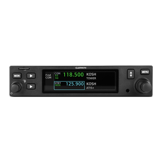
Equipment Description The GTR 205x is a 1.35" panel mounted COM product, while the GTR 205xR is a 1.35" remote mounted COM product. The GTR 205x features a high-resolution LCD display, dual encoder knob, and a microSD card slot. The GTR 205xR is a remote-mounted unit. -
Page 15: General Specifications
10.32" (262.1 mm) of aircraft panel to rear of connector backshells) GTR 205x weight (unit only) 2.2 lbs. (1.0 kg) GTR 205x installed with rack and connectors 2.8 lbs. (1.4 kg) GTR 205xR weight (unit only) 2.0 lbs. (0.9 kg) GTR 205xR installed with rack and connectors 2.6 lbs. -
Page 16: Com Specifications
At least 35 dB (SNR) Stuck mic time-out 30 seconds time-out, reverts to receive Less than 5% distortion when the transmitter is at 90% modulation at Demodulated audio distortion 350 to 2500 Hz. 190-02766-21 GTR 205x/GTR 205xR Installation Manual Rev. 1 Page 1-4... -
Page 17: Current Draw Specifications
0.63 A 3.35 A 0.33 A 1.61 A [1] The specified current draw is with the display backlight set to 100%. [2] There is no support for 16 W functionality. 190-02766-21 GTR 205x/GTR 205xR Installation Manual Rev. 1 Page 1-5... -
Page 18: License Requirements
The GTR has a database of frequencies for airports. Users update the frequency database by purchasing database subscription updates from Garmin or Jeppesen. The frequency database is stored internally and uses a micro-SD card to transfer the database into the unit. Refer to the applicable GTR pilot's guide or go to flyGarmin.com... -
Page 19: Limitations
The unit must not be installed in areas where water or fluid contamination could be commonly encountered. Aircraft Radio An aircraft radio station license is not required when operating in U.S. airspace, but may be required when operating internationally. 190-02766-21 GTR 205x/GTR 205xR Installation Manual Rev. 1 Page 2-1... -
Page 20: Installation Overview
For installations that may provide direct exposure, the limits specified by FCC regulations 47 CFR 1.1310 should be referenced by the installer. 190-02766-21 GTR 205x/GTR 205xR Installation Manual Rev. 1 Page 3-1... -
Page 21: Mounting Considerations
If aircraft has a throw-over yoke, be sure the yoke does not interfere with the unit. For remote mounting considerations, refer to Remote Mount section. 190-02766-21 GTR 205x/GTR 205xR Installation Manual Rev. 1 Page 3-2... -
Page 22: Cabling And Wiring Considerations
After reconfiguring the avionics in the cockpit panel, if the unit is mounted less than 12" from the compass, recalibrate the compass and make the necessary changes for noting correction data. 190-02766-21 GTR 205x/GTR 205xR Installation Manual Rev. 1 Page 3-3... -
Page 23: Installation Procedures
4.4.2 Materials Required but Not Supplied (New Installations Only) ..............4-4 4.5 Special Tools Required .............................4-5 4.6 Coaxial Cable Installation ..........................4-6 4.7 Equipment Mounting............................4-6 4.7.1 Installation..............................4-6 4.8 Antenna Installation and Connections ......................4-8 4.8.1 COM Antenna............................4-8 4.9 Electrical Installation Procedure ........................4-9 190-02766-21 GTR 205x/GTR 205xR Installation Manual Rev. 1 Page 4-1... -
Page 24: Unit And Accessories
Connector kit 011-05779-10 Backplate assembly 011-05691-00 GTR 205x/GTR 205xR 115-03651-00 Mounting rack 115-04497-00 Product information kit (GTR 205x) K00-01298-10 Product information kit (GTR 205xR) K00-01298-11 [1] Not applicable to GTR 205xR models. Table 4-3 Replaceable Parts Item Knob replacement kit... -
Page 25: Miscellaneous Options
GPS 1.57542 GHz notch filter 330-00067-00 Connector, TNC, male, clamp 031-4452 [1] [1] This part is not available from Garmin. Vendor Contact Information (provided for convenience only): Amphenol RF, Four Old Newtown Road, Danbury, CT 06810 Phone: (800) 627-7100 Reference Documents... -
Page 26: Installation Materials Required But Not Supplied
• Push/pull (manually resettable) circuit breakers • Tie wraps or lacing cord • Ring terminals (for grounding) • Coaxial cable (RG-400, RG-142B or equivalent. Refer to section 4.8 for additional information) 190-02766-21 GTR 205x/GTR 205xR Installation Manual Rev. 1 Page 4-4... -
Page 27: Special Tools Required
Table 4-10 Socket Contact P/Ns Wire Gauge 22-28 AWG Garmin P/N 336-00021-00 Military P/N M39029/58-360 [1] [1] Non-Garmin part numbers shown are not maintained by Garmin and are subject to change without notice. 190-02766-21 GTR 205x/GTR 205xR Installation Manual Rev. 1 Page 4-5... -
Page 28: Coaxial Cable Installation
2. Insert a 3/32" hex drive tool into the access hole at the bottom of the unit face. 3. Turn the hex tool clockwise while pressing on the left side of the bezel until the unit is seated in the rack. 190-02766-21 GTR 205x/GTR 205xR Installation Manual Rev. 1 Page 4-6... - Page 29 Attach the connectors to the connector backplate the same way as panel mount units. Refer to Panel Mount section. Unit Replacement Whenever the unit is reinstalled, verify the unit powers up successfully. 190-02766-21 GTR 205x/GTR 205xR Installation Manual Rev. 1 Page 4-7...
-
Page 30: Antenna Installation And Connections
6" in-line BNC connection. This would be an acceptable place to insert the VSWR meter. Any problem with the antenna installation is most likely seen as high reflected power. A VSWR of 3:1 may result in up to a 50% loss in transmit power. 190-02766-21 GTR 205x/GTR 205xR Installation Manual Rev. 1 Page 4-8... -
Page 31: Electrical Installation Procedure
Route the wire harness, avoiding sharp bends and providing adequate space. The connector kit includes the backshell assembly. Table 4-11 lists part numbers for the D-sub connectors and the backshell assembly. 190-02766-21 GTR 205x/GTR 205xR Installation Manual Rev. 1 Page 4-9... -
Page 32: Table 4-11 Backshell Assembly
[3] Not supplied - must be purchased separately. [4] Solder sleeve with pre-installed shield drain wire may be used instead of items 9 and 10. [5] Not a Garmin part number. CAUTION THE SCREWS (13) USED TO GROUND THE SHIELDS TO THE SHIELD BLOCK SHOULD PENETRATE TWO TO FOUR THREADS PAST THE SHIELD BLOCK. -
Page 33: Figure 4-1 Shielded Cable Preparation
NO LONGER THAN 3" PREFERRED METHOD 2.5" MAX .31" MAX. OF EXPOSED SHIELD 0.17" SHIELD DRAINS AS SHORT AS PRACTICAL NO LONGER THAN 3" ALTERNATE METHOD Figure 4-1 Shielded Cable Preparation 190-02766-21 GTR 205x/GTR 205xR Installation Manual Rev. 1 Page 4-11... - Page 34 11. Insert the pin into the connector (7) in accordance with wiring diagrams in section 10. 12. Verify that the pin is properly engaged into the connector by gently tugging on the wire. 190-02766-21 GTR 205x/GTR 205xR Installation Manual Rev. 1 Page 4-12...
-
Page 35: Figure 4-2 Preferred Method Of Shield Termination On Backshell Assembly
Installation Procedures .31” MAX. EXPOSED SHIELD Figure 4-2 Preferred Method of Shield Termination on Backshell Assembly 190-02766-21 GTR 205x/GTR 205xR Installation Manual Rev. 1 Page 4-13... - Page 36 7. Insert the screw (13) into the tapped holes on the backshell. 8. Insert the assembled connector into the backplate. 9. Secure the connector (7) into the backplate with screws (2). 190-02766-21 GTR 205x/GTR 205xR Installation Manual Rev. 1 Page 4-14...
-
Page 37: Figure 4-3 Connector And Backshell Assembly
Installation Procedures 6 x2 3 x3 Figure 4-3 Connector and Backshell Assembly 190-02766-21 GTR 205x/GTR 205xR Installation Manual Rev. 1 Page 4-15... -
Page 38: Connector Pinout Information
5.2.4 Serial Data – RS-232 ..........................5-9 5.2.5 COM Audio ..............................5-9 5.2.6 COM Discrete Inputs ..........................5-11 5.2.7 Configurable Discrete Inputs ........................5-11 5.2.8 Configuration Module..........................5-12 5.2.9 AUX Pins..............................5-13 5.2.10 CAN Bus Pins ............................5-13 190-02766-21 GTR 205x/GTR 205xR Installation Manual Rev. 1 Page 5-1... -
Page 39: Pin Function List
HEADSET 2 AUDIO OUT RIGHT HEADSET 1 AUDIO OUT RIGHT AUX 3 AUDIO IN HI AUX 2 AUDIO IN HI AUX 1 AUDIO IN HI DISC 5* SPEAKER AUDIO OUT HI 190-02766-21 GTR 205x/GTR 205xR Installation Manual Rev. 1 Page 5-2... - Page 40 MIC 2 AUDIO IN LO MIC 1 AUDIO IN LO AIRCRAFT GND AIRCRAFT POWER CONFIG MODULE POWER CAN BUS LO CAN BUS HI RS-232 IN CAN BUS TERM B CAN BUS TERM A 190-02766-21 GTR 205x/GTR 205xR Installation Manual Rev. 1 Page 5-3...
- Page 41 AIRCRAFT POWER An asterisk (*) following a signal name denotes that the signal is an Active-Low, requiring a ground to activate. If there is no asterisk, the signal is an Active-High. 190-02766-21 GTR 205x/GTR 205xR Installation Manual Rev. 1 Page 5-4...
-
Page 42: Table 5-2 Gtr 205Xr Pins
HEADSET 1 AUDIO OUT RIGHT AUX 3 AUDIO IN HI AUX 2 AUDIO IN HI AUX 1 AUDIO IN HI UNIT ID IN SPEAKER AUDIO OUT HI COM AUDIO OUT HI RESERVED 190-02766-21 GTR 205x/GTR 205xR Installation Manual Rev. 1 Page 5-5... - Page 43 MIC 1 AUDIO IN LO AICRAFT GROUND AIRCRAFT POWER RESERVED CAN BUS LO CAN BUS HI RS-232 IN CAN BUS TERM B CAN BUS TERM A RESERVED HEADSET 2 AUDIO OUT LEFT 190-02766-21 GTR 205x/GTR 205xR Installation Manual Rev. 1 Page 5-6...
- Page 44 AUX 4 AUDIO IN HI TX INTERLOCK OUT EXTERNAL COM KEY OUT DISC 4* DISC 3* DISC 2* DISC 1* COM MIC 2 KEY* COM MIC 1 KEY * AIRCRAFT GROUND AIRCRAFT POWER 190-02766-21 GTR 205x/GTR 205xR Installation Manual Rev. 1 Page 5-7...
-
Page 45: Functional Descriptions
Table 5-4 Lighting Pins Pin Name LIGHTING BUS HI LIGHTING BUS LO 5.2.3 Antennas Antennas use BNC coaxial connectors on the connector backplate. Table 5-5 Antenna Pins Pin Name COM ANTENNA 190-02766-21 GTR 205x/GTR 205xR Installation Manual Rev. 1 Page 5-8... -
Page 46: Serial Data - Rs-232
Activation of COM MIC 2 TRANSMIT enables MIC 2 AUDIO IN HI and causes the transceiver to transmit. 500 Ω COM AUDIO is a 65 mW audio output that is intended to drive a headset or an audio panel. 190-02766-21 GTR 205x/GTR 205xR Installation Manual Rev. 1 Page 5-9... - Page 47 COM AUDIO is the summation of the COM receiver audio, COM sidetone audio, and intercom audio. Table 5-8 COM Audio Pins Pin Name COM AUDIO OUT HI COM AUDIO OUT LO 190-02766-21 GTR 205x/GTR 205xR Installation Manual Rev. 1 Page 5-10...
-
Page 48: Table 5-9 Com Discrete Inputs
COM STANDBY MONITOR* The COM STANDBY MONITOR* discrete input is used to monitor standby COM frequency audio. A momentary low on this pin will toggle the COM standby monitor ON and OFF. 190-02766-21 GTR 205x/GTR 205xR Installation Manual Rev. 1 Page 5-11... -
Page 49: Table 5-10 Configurable Discrete Input Pins
An asterisk (*) following a signal name denotes that the signal is an Active-Low, requiring a ground to activate. 5.2.8 Configuration Module Table 5-11 Configuration Module Pin Name CONFIG MODULE CLOCK CONFIG MODULE DATA CONFIG MODULE GROUND CONFIG MODULE POWER 190-02766-21 GTR 205x/GTR 205xR Installation Manual Rev. 1 Page 5-12... -
Page 50: Figure 5-1 Can Bus Pins
CAN BUS HI CAN BUS LO CAN_TERM_A NOTE: JUMPER (BETWEEN PINS 47 & 48) REQUIRED WHEN GTR 205x/GTR 205xR IS LOCATED AT END OF CAN BUS CAN _TERM_B Figure 5-1 CAN Bus Pins Table 5-13 CAN Bus Pins Pin Name... -
Page 51: System Configuration
6.6.1 Discrete Input Checkout ..........................6-27 6.6.2 VHF COM ...............................6-28 6.6.3 Database Check ............................6-28 6.6.4 Serial Interface Checks..........................6-28 6.7 Flight Checks ..............................6-29 6.7.1 COM Flight Check ...........................6-29 6.8 Software Loading............................6-30 6.9 Screenshots ..............................6-31 190-02766-21 GTR 205x/GTR 205xR Installation Manual Rev. 1 Page 6-1... -
Page 52: Figure 6-1 Gtr 205X System Configuration Map
System Configuration System at a Glance This section provides complete instructions for configuring GTR 205x functionality. Screenshots are for reference only. SYS Setup Unit Setup Interfaces SD Save Test Diagnostics SYS INFO Audio Digital Unit ID RS-232 SW Upload Database... -
Page 53: System Configuration Overview
DIMMING BUS AT THE LOWEST SETTING, AND SLOWLY INCREASE THE BRIGHTNESS. VERIFY THE WIRING IS CORRECT IF IT IS NOTICED THE LIGHTING LEVEL ON THE GTR 205x/GTR 205xR DOES NOT INCREASE AS THE LIGHTING BUS INPUT IS INCREASED IN BRIGHTNESS. -
Page 54: Configuration Mode Operations
2. Press and hold the right inner knob. 3. Apply power to the unit by turning the COM volume knob. 4. When “Garmin” appears on the screen release knob. The first page displayed is the Configuration Mode Home page. • SYS Setup •... -
Page 55: Figure 6-3 Sys Info Page
• Database Key part number • Boot block lock version • Boot block part number • Hardware Version Figure 6-3 SYS Info Page SW Upload Figure 6-4 SW Upload Page 190-02766-21 GTR 205x/GTR 205xR Installation Manual Rev. 1 Page 6-5... -
Page 56: Figure 6-5 Tail Number Page
Figure 6-5 Tail Number Page Enablement An enablement card is necessary to activate Night Vision and 16W COM Transmit features. A green bar displays when the feature is active. Figure 6-6 Enablement Page 190-02766-21 GTR 205x/GTR 205xR Installation Manual Rev. 1 Page 6-6... -
Page 57: Figure 6-7 Unit Id Page
Unit ID sets the unit as GTR 1 or GTR 2. Table 6-1 Unit ID Selections Selection Setting Description GTR 1 (Default) COM #1 Unit ID GTR 2 COM #2 Figure 6-7 Unit ID Page 190-02766-21 GTR 205x/GTR 205xR Installation Manual Rev. 1 Page 6-7... -
Page 58: Figure 6-8 Database Page
Database Selections Selection Setting Description The unit utilizes the Navigation database installed Internal locally. Database The unit utilizes the Navigation database installed External on an interfaced device. Figure 6-8 Database Page 190-02766-21 GTR 205x/GTR 205xR Installation Manual Rev. 1 Page 6-8... -
Page 59: Figure 6-9 Ics/Audio Page
Speaker Volume 0% to 100% Adjusts the volume output of the speaker. Enable Bluetooth is enabled if a green bar displays. Bluetooth Disable Bluetooth is disabled. Figure 6-9 ICS/Audio Page 190-02766-21 GTR 205x/GTR 205xR Installation Manual Rev. 1 Page 6-9... -
Page 60: Figure 6-10 Aux Audio Input Configuration Page
0% to 100% AUX 4 Unswitched 0% to 100% Stereo Left AUX Squelch 0% to 100% [1] Customize to desired four character label. Figure 6-10 AUX Audio Input Configuration Page 190-02766-21 GTR 205x/GTR 205xR Installation Manual Rev. 1 Page 6-10... -
Page 61: Figure 6-11 Unit Lighting Page
Description Photocell Photocell on unit bezel controls backlight level. Source Lighting Bus Lighting bus controls backlight. Min Level 0% - 100% Minimum backlight brightness setting. Figure 6-12 Source/Level Configuration Page 190-02766-21 GTR 205x/GTR 205xR Installation Manual Rev. 1 Page 6-11... -
Page 62: Figure 6-13 Photocell Configuration Page
Transition (Default is 25) to control the unit display backlight. The photocell transition is a percentage of the maximum lighting bus input level. Figure 6-13 Photocell Configuration Page 190-02766-21 GTR 205x/GTR 205xR Installation Manual Rev. 1 Page 6-12... -
Page 63: Figure 6-14 Lighting Bus Configuration Page
Reset to Default Selections Selection Description Reset Resets all lighting settings to default values. Cancel Exits the prompt and keeps the current lighting settings. Figure 6-15 Reset to Defaults Page 190-02766-21 GTR 205x/GTR 205xR Installation Manual Rev. 1 Page 6-13... -
Page 64: Figure 6-16 Com Options Page
(Default is 4) transmitted via COM radio. Resets squelch, sidetone volume, and TX MIC gain settings to default values. Reset to Defaults Exits the prompt and keeps the current settings. 190-02766-21 GTR 205x/GTR 205xR Installation Manual Rev. 1 Page 6-14... -
Page 65: Figure 6-17 Com Levels Page
RX Squelch Open COM RX Squelch Approximation Setting (%) [1] (dBm) -89.5 43 (Default) 82.5 [1] The COM Carrier range (0-100) is a linear response. Figure 6-17 COM Levels Page 190-02766-21 GTR 205x/GTR 205xR Installation Manual Rev. 1 Page 6-15... -
Page 66: Figure 6-18 Rs-232 Page
GTR with this selection. Serial data “RS-232 NMEA” input/output as defined in NMEA 1 section 8.2 (for example, with G500/G600, GPSMap, Aera Series, XL Series, or G3X Touch). Figure 6-18 RS-232 Page 190-02766-21 GTR 205x/GTR 205xR Installation Manual Rev. 1 Page 6-16... -
Page 67: Figure 6-19 Hsdb (Ethernet) Settings Page
System Configuration HSDB HSDB (Ethernet) Settings NOTE Refer to the LRU installation manual for compatibility information. Visit Garmin’s Dealer Resource Center and search by product name. Table 6-14 HSDB (Ethernet) Setting Selections Selection Setting Description Present Configure if a GPS navigator such as GPS 175 or GTN Xi GPS Navigator is present on the HSDB (Ethernet) network. -
Page 68: Figure 6-21 Discrete In Selections
System Configuration Discrete In NOTE Discrete 5 is available only on the GTR 205x. Table 6-15 Discrete In Selections Selection Description Discrete Off No discrete selected. Used to flip-flop between active and standby COM frequencies. It COM Remote Transfer may also be used tune the emergency COM frequency 121.500MHz. -
Page 69: Figure 6-22 Sd Save Pages
Saving to an SD card allows information to display on a PC, emailed, or printed. The saved information includes: • Printable summary of all configuration settings (HTML) • Printable maintenance log • Error log Figure 6-22 SD Save Pages 190-02766-21 GTR 205x/GTR 205xR Installation Manual Rev. 1 Page 6-19... -
Page 70: Figure 6-23 Test Page
Displays total power ups and operating hours. Displays temperature of main board, LED board, and COM Temps transmitter. Allows the clearing of the maintenance log, configuration settings, Clear/Delete and deleting the database. Figure 6-24 Diagnostics Page 190-02766-21 GTR 205x/GTR 205xR Installation Manual Rev. 1 Page 6-20... -
Page 71: Figure 6-25 Rs-232 Diagnostic Page
Figure 6-26 HSDB (Ethernet) Diagnostic Page View CAN Bus Status Diagnostics > Digital > View CAN Bus Status displays the status of the network bus. Figure 6-27 CAN Bus Diagnostic Page 190-02766-21 GTR 205x/GTR 205xR Installation Manual Rev. 1 Page 6-21... -
Page 72: Figure 6-28 Discrete In Page
Diagnostics > Discrete > View Discrete Outputs displays the status of discrete outputs. Figure 6-29 Discrete Out Page Analog In Diagnostics > Analog In displays the bus setting and input voltage. Figure 6-30 Analog In Pages 190-02766-21 GTR 205x/GTR 205xR Installation Manual Rev. 1 Page 6-22... -
Page 73: Figure 6-31 Power Stats Page
Diagnostics > Power Stats displays the number of Total Power-ups and Operating Hours. Figure 6-31 Power Stats Page Temps Diagnostics > Temps displays the temperatures of Main Board, LED board, and COM Transmitter. Figure 6-32 Temps Page 190-02766-21 GTR 205x/GTR 205xR Installation Manual Rev. 1 Page 6-23... -
Page 74: Figure 6-33 Clear/Delete Pages
“Clear Complete” prompt displays when logs are cleared. Figure 6-35 Clear Complete Prompt Selecting Clear Config Settings prompts a warning. Select Yes or No to proceed. Figure 6-36 Configuration Options Warning 190-02766-21 GTR 205x/GTR 205xR Installation Manual Rev. 1 Page 6-24... -
Page 75: Figure 6-37 Configuration Options Reset
If Yes is selected, a unit restart is necessary. Figure 6-37 Configuration Options Reset Selecting Delete Database prompts a warning. Select Yes or No to proceed. Figure 6-38 Warning of Deleting Databases 190-02766-21 GTR 205x/GTR 205xR Installation Manual Rev. 1 Page 6-25... -
Page 76: Ground Checks (Configuration Mode)
6.5.1 Lighting Bus Interface Check CAUTION WHEN 14 VDC OR 28 VDC LIGHTING BUSES ARE CONNECTED TO THE GTR 205x, CONNECTION OF THE AIRCRAFT LIGHTING BUS TO THE INCORRECT INPUT PINS CAN CAUSE DAMAGE TO THE GTR 205x. ALWAYS START THIS TEST WITH THE DIMMING BUS AT THE LOWEST SETTING, AND SLOWLY INCREASE THE BRIGHTNESS. -
Page 77: Ground Checks (Normal Mode)
Activates and deactivates the standby COM monitor. TX INTERLOCK Desensitizes the receiver of the COM radio. PILOT ICS KEY Activates the pilot’s microphone for the ICS. COPILOT ICS KEY Activates the copilot’s microphone for the ICS. 190-02766-21 GTR 205x/GTR 205xR Installation Manual Rev. 1 Page 6-27... -
Page 78: Vhf Com
3. Verify the connected GPS source has a valid GPS satellite fix. 4. Press FIND. 5. Turn the outer knob to NEAREST APT. 6. Verify the wiring between the GPS source and the GTR if the unit displays “No GPS Position.” 190-02766-21 GTR 205x/GTR 205xR Installation Manual Rev. 1 Page 6-28... -
Page 79: Flight Checks
It may be required by the governing regulatory agency to verify operation of the COM transmitter and receiver at the extents of a ground facility’s service volume (e.g., FAA AC 23-8A). 190-02766-21 GTR 205x/GTR 205xR Installation Manual Rev. 1 Page 6-29... -
Page 80: Software Loading
System Configuration Software Loading The unit comes pre-loaded with software. It is recommended software from a current GTR Downloadable Software microSD Card, P/N 006-B4769-XX, be loaded into the unit. Visit Garmin’s website and search by product name. For dual installations the software loading procedures below must be carried out on each unit. Refer to section 6.4 for instructions pertaining to entering configuration mode. -
Page 81: Screenshots
3. Push and hold MON. 4. Push and release to top soft key. Soft Key When the screenshot is successful, a camera icon briefly displays in the annunciator bar. Figure 6-40 Screenshots 190-02766-21 GTR 205x/GTR 205xR Installation Manual Rev. 1 Page 6-31... -
Page 82: Continued Airworthiness
Other than for regulatory checks, maintenance of the GTR 205x/GTR 205xR is “on condition” only. Periodic maintenance of the GTR 205x/GTR 205xR is not required. Instructions for Continued Airworthiness are not required for this product under 14 CFR Part 21 since the GTR 205x/GTR 205xR has received no FAA approval or endorsement. 190-02766-21 GTR 205x/GTR 205xR Installation Manual Rev. -
Page 83: Data Format
8.1.3 Aviation Output Sentence Type 1 ......................8-2 8.1.4 Aviation Output Sentence Type 2 ......................8-4 8.2 RS-232 NMEA Data Format..........................8-6 8.2.1 Electrical Interface.............................8-6 8.2.2 Message Formats ............................8-6 8.2.3 Message Output Rate..........................8-7 8.2.4 Message Definitions ..........................8-7 190-02766-21 GTR 205x/GTR 205xR Installation Manual Rev. 1 Page 8-1... -
Page 84: Aviation Format
Table 8-3 describes the Type 1 output sentence item designator (id) and item data (dddd) fields. If data for these sentences is invalid or unavailable, dashes ("-") are used to fill in all non-blank character positions. 190-02766-21 GTR 205x/GTR 205xR Installation Manual Rev. 1 Page 8-2... - Page 85 - N (NAV flagged) or - (NAV valid) Warnings status, only data transmitted are dashes (-). Used to indicate end of Type 1 sentences. l (lower case Distance to destination waypoint in tenths of Lima) nautical miles. 190-02766-21 GTR 205x/GTR 205xR Installation Manual Rev. 1 Page 8-3...
-
Page 86: Table 8-5 Aviation Output Sentence Type 2 - No Route
(3 ASCII characters; route sequence number is “01”) sequence number (1 binary byte; last waypoint flag is set; route sequence number is 1) ASCII carriage return character (0D hex) ASCII line feed character (0A hex) 190-02766-21 GTR 205x/GTR 205xR Installation Manual Rev. 1 Page 8-4... -
Page 87: Table 8-6 Type 2 Aviation Output Sentence Format
(unsigned binary) undefined mmmmmm latitude minutes (unsigned binary) undefined hhhhhhh hundredths of latitude minutes (unsigned binary) Two's complement binary in 16ths of degrees. Easterly mvar variation is positive. MSB output first. 190-02766-21 GTR 205x/GTR 205xR Installation Manual Rev. 1 Page 8-5... -
Page 88: Nmea Data Format
[1] Encoded hex: each character consists of 4 bits of data placed in the low order nibble +30h. For example, the 8-bit value 5Fh would be encoded as two characters with values of 35h and 3Fh, which map to the ASCII characters “5” and “?”, respectively. 190-02766-21 GTR 205x/GTR 205xR Installation Manual Rev. 1 Page 8-6... -
Page 89: Message Output Rate
Remote Flight Service Station < Unicom Mandatory Frequency > No type specified Undefined Center Automated Surface Observing Station Class B Class C Radio Enroute Enroute Flight Advisory Service or Flight Watch 190-02766-21 GTR 205x/GTR 205xR Installation Manual Rev. 1 Page 8-7... - Page 90 Data Format CHARACTER DESCRIPTION Gate Helicopter Information Weather Terminal Pilot controlled lighting Multicom Radar Operations Ramp Reserved - Undefined 190-02766-21 GTR 205x/GTR 205xR Installation Manual Rev. 1 Page 8-8...
-
Page 91: Table 8-10 Message Format (Gtr Com Requests)
14 = Request Unit Display Information. Message sub-id; set to (ASCII) 1 for Request COM Audio Volume, 0 otherwise. “00” Reserved. MESSAGE EXAMPLE $PGRMC0613000<chksm><CR><LF> Request the GTR to send the current COM status. 190-02766-21 GTR 205x/GTR 205xR Installation Manual Rev. 1 Page 8-9... -
Page 92: Table 8-11 Active Com Frequency And Transceiver Message Format
119 for the MHz portion. The kHz portion converts ASCII “4” to 34h, -30h yields 4h, x 25 kHz steps = 100 kHz, with no 8.33 kHz channel offsets. 190-02766-21 GTR 205x/GTR 205xR Installation Manual Rev. 1 Page 8-10... -
Page 93: Table 8-12 Standby Com Frequency And Transceiver Message Format
123 for the MHz portion. The kHz portion converts ASCII “F” to 46h, -30h yields 16h, x25 kHz steps = 550 kHz, add 3 8.33 channels = 565 kHz. 190-02766-21 GTR 205x/GTR 205xR Installation Manual Rev. 1 Page 8-11... -
Page 94: Table 8-13 Com Level And Audio Control Message Format
Message class. This is a GTR COM message. “03” Message ident. Squelch test: (ASCII) 0 = automatic 1 = manual override (displays “SQ”) MESSAGE EXAMPLE $PGRMC030<chksm><CR><LF> Set the squelch to automatic operation. 190-02766-21 GTR 205x/GTR 205xR Installation Manual Rev. 1 Page 8-12... -
Page 95: Table 8-15 Remote Airport Identifier Name Message Format
3 = third 8.33 kHz channel offset (.015) MESSAGE EXAMPLE $PGRMC054<JP0<chksm><CR><LF> Append 122800 to the end of the airport frequency list at index 4 with a frequency type of UNICOM. 190-02766-21 GTR 205x/GTR 205xR Installation Manual Rev. 1 Page 8-13... -
Page 96: Table 8-17 Active Com Frequency With Identifier Message Format
MESSAGE EXAMPLE $PGRMC15F0N0ABC I<chksm><CR><LF> Set the active COM frequency to 118.000 MHz, the transceiver to normal (not monitor) mode, and the displayed text to ABC<sp> along with the Information frequency type. 190-02766-21 GTR 205x/GTR 205xR Installation Manual Rev. 1 Page 8-14... -
Page 97: Table 8-18 Standby Com Frequency With Identifier Message Format
MESSAGE EXAMPLE $PGRMC16F0N0ABC I<chksm><CR><LF> Set the standby COM frequency to 118.000 MHz, the transceiver to normal (not monitor) mode, and the displayed text to ABC<sp> along with the Information frequency type. 190-02766-21 GTR 205x/GTR 205xR Installation Manual Rev. 1 Page 8-15... -
Page 98: Table 8-19 Set Com Frequency Lookup Table Entry Message Format
Frequency index (000 to 299) Number of sequential frequencies to delete (minimum 001 to 300) MESSAGE EXAMPLE $PGRMC18000010<chksm><CR><LF> Delete ten entries from the COM frequency lookup table starting at index 0. 190-02766-21 GTR 205x/GTR 205xR Installation Manual Rev. 1 Page 8-16... -
Page 99: Table 8-21 Com Keypad Input Message Format
Message class. This is a GTR COM message. “19” Message identifier. Key press: F = Flip-Flop key; M = MON key. MESSAGE EXAMPLE $PGRMC19M<chksm><CR><LF> Toggle the standby frequency monitor mode. 190-02766-21 GTR 205x/GTR 205xR Installation Manual Rev. 1 Page 8-17... -
Page 100: Table 8-22 Com Transceiver Status Message Format
0 = 25 kHz frequency (.000) 1 = first 8.33 kHz channel offset (.005) 2 = second 8.33 kHz channel offset (.010) 3 = third 8.33 kHz channel offset (.015) 190-02766-21 GTR 205x/GTR 205xR Installation Manual Rev. 1 Page 8-18... -
Page 101: Table 8-23 Com Volume Level Message Format
Table 8-24 COM Software Version Message Format CHARACTER DESCRIPTION “C” Message class. This is a GTR COM message. “03” Message identifier. vvvv Software version in ASCII. MESSAGE EXAMPLE $PGRMC030100<chksm><CR><LF> COM Software version is 01.00. 190-02766-21 GTR 205x/GTR 205xR Installation Manual Rev. 1 Page 8-19... -
Page 102: Table 8-25 Gtr Com Message Format
Display application software version, including ASCII decimal, with no leading (v)v.vv zero for software versions less than 10.00. MESSAGE EXAMPLE $PGRMC14GTR 205,006-B3896-02,2.11<chksm><CR><LF> A GTR 205 with software product number 006-B3896-00, software version 2.20. 190-02766-21 GTR 205x/GTR 205xR Installation Manual Rev. 1 Page 8-20... -
Page 103: Table 8-27 Gtr Com Error Message Format
Set Standby COM Frequency With Identifier COM Transceiver Status Set COM Frequency Lookup Table Entry Remove COM Frequency Lookup Table Entries COM Keypad Input COM Transceiver Status Notes Class: “C” = GTR COM message. 190-02766-21 GTR 205x/GTR 205xR Installation Manual Rev. 1 Page 8-21... -
Page 104: Table 8-29 Output Message Summary
Upon Request / Status Change COM Software Version Upon Request COM Communications Error When Error Detected At Startup / Upon Request / COM Radio Status Status Change Unit Display Information Upon Request 190-02766-21 GTR 205x/GTR 205xR Installation Manual Rev. 1 Page 8-22... -
Page 105: Mechanical Drawings
Mechanical Drawings 9 Mechanical Drawings Figure 9-1 GTR 205x Dimensions and Center of Gravity ..................9-2 Figure 9-2 GTR 205xR Dimensions and Center of Gravity..................9-3 Figure 9-3 Rear Connector Layout Detail.......................9-4 Figure 9-4 Panel Cutout Detail..........................9-5 Figure 9-5 Mounting Rack Installation ........................9-6 Figure 9-6 Mounting Rack............................9-7... -
Page 106: Figure 9-1 Gtr 205X Dimensions And Center Of Gravity
.437 11.10 6.563 166.70 TO "0.025" DIMPLES DIMENSIONS: INCHES [mm] PRODUCT "A" "B" "C" GTR 205x 3.25 [82.6] 4.47 [113.5] 0.50 [12.7] Figure 9-1 GTR 205x Dimensions and Center of Gravity 190-02766-21 GTR 205x/GTR 205xR Installation Manual Rev. 1 Page 9-2... -
Page 107: Figure 9-2 Gtr 205Xr Dimensions And Center Of Gravity
1.350 34.30 TO "0.25" FRONT COVER DIMPLES "C" .388 9.84 .300 7.62 .437 11.10 6.563 166.70 TO "0.25" DIMPLES DIMENSIONS: INCHES [mm] Figure 9-2 GTR 205xR Dimensions and Center of Gravity 190-02766-21 GTR 205x/GTR 205xR Installation Manual Rev. 1 Page 9-3... -
Page 108: Figure 9-3 Rear Connector Layout Detail
Mechanical Drawings (62 PIN) Figure 9-3 Rear Connector Layout Detail 190-02766-21 GTR 205x/GTR 205xR Installation Manual Rev. 1 Page 9-4... -
Page 109: Figure 9-4 Panel Cutout Detail
2. IF THE FRONT LIP OF THE MOUNTING RACK IS BEHIND THE SURFACE OF THE AIRCRAFT INSTRUMENT PANEL, THE UNIT CONNECTORS MAY NOT FULLY ENGAGE. 3. TOLERANCE: +0.03" Figure 9-4 Panel Cutout Detail 190-02766-21 GTR 205x/GTR 205xR Installation Manual Rev. 1 Page 9-5... -
Page 110: Figure 9-5 Mounting Rack Installation
SCREW, 4-40 x 0.25 (4X) 1 PROVIDED WITH BACKPLATE ASSEMBLY 211-63234-08 SCREW, 4-40 x 0.25 (2X) 1 PROVIDED WITH CONNECTOR KIT 115-04497-00 MOUNTING RACK TORQUE TO 8 1 IN-LB Figure 9-5 Mounting Rack Installation 190-02766-21 GTR 205x/GTR 205xR Installation Manual Rev. 1 Page 9-6... -
Page 111: Figure 9-6 Mounting Rack
DURING INSTALLATION OF THE MOUNTING RACK, ENSURE EDGE OF THE TAB (TOP & BOTTOM FLANGE OF THE RACK) IS FLUSH WITH THE FACE OF THE INSTRUMENT PANEL Figure 9-6 Mounting Rack 190-02766-21 GTR 205x/GTR 205xR Installation Manual Rev. 1 Page 9-7... -
Page 112: Interconnect Diagrams
Figure 10-3 Power Lighting Configuration Interconnect ..................10-5 Figure 10-4 GTR 205x GPS Interconnect ......................10-6 Figure 10-5 Audio Panel Interconnect ........................10-8 Figure 10-6 GTR 205x/GTR 205xR EFIS Interconnect .....................10-9 Figure 10-7 GTR 205x/GTR 205xR Intercom Interconnect ...................10-11 190-02766-21 GTR 205x/GTR 205xR Installation Manual Rev. - Page 113 • ~ indicates any available similar functioning port or pin may be used. Ports or pins without ~ must be connected as shown • * indicates an active low pin. • † indicates an active high pin. 190-02766-21 GTR 205x/GTR 205xR Installation Manual Rev. 1 Page 10-2...
-
Page 114: Figure 10-1 Gtr 205X Typical Installation
AVIONICS BUS AIRCRAFT POWER 5A (28 VDC) 10A (14 VDC) AIRCRAFT POWER AIRCRAFT GND AIRCRAFT AIRCRAFT GND GROUND AIRCRAFT GND COM ANTENNA COM ANTENNA Figure 10-1 GTR 205x Typical Installation 190-02766-21 GTR 205x/GTR 205xR Installation Manual Rev. 1 Page 10-3... -
Page 115: Figure 10-2 Gtr 205Xr Typical Installation
AVIONICS BUS AIRCRAFT POWER 5A (28 VDC) 10A (14 VDC) AIRCRAFT POWER AIRCRAFT GND AIRCRAFT AIRCRAFT GND GROUND AIRCRAFT GND COM ANTENNA COM ANTENNA Figure 10-2 GTR 205xR Typical Installation 190-02766-21 GTR 205x/GTR 205xR Installation Manual Rev. 1 Page 10-4... -
Page 116: Figure 10-3 Power Lighting Configuration Interconnect
THE SUPPLIED CONFIGURATION MODULE HARNESS USES 28 AWG WIRE. USE THE CONTACTS SUPPLIED WITH THE CONFIGURATION MODULE. LIGHTING BUS NOT APPLICABLE TO THE GTR 205xR. CONFIGURATION MODULE NOT APPLICABLE TO THE GTR 205xR. Figure 10-3 Power Lighting Configuration Interconnect 190-02766-21 GTR 205x/GTR 205xR Installation Manual Rev. 1 Page 10-5... -
Page 117: Figure 10-4 Gtr 205X Gps Interconnect
CONFIGURE RS-232 OUTPUT TO "MAPCOM" FORMAT. RS-232 OUTPUT PORT 1 OR PORT 5 MAY BE USED. CONFIGURE RS-232 OUTPUT TO "AVIATION OUTPUT 1" FORMAT. ANY AVAILABLE RS-232 OUTPUT PORT MAY BE USED. Figure 10-4 GTR 205x GPS Interconnect Sheet 1 of 2 190-02766-21 GTR 205x/GTR 205xR Installation Manual Rev. - Page 118 USED. CONFIGURE GTR GPS NAVIGATOR STATUS TO "PRESENT". USE EITHER HSDB (ETHERNET) OR RS-232, NOT BOTH. HSDB (ETHERNET) IS THE PREFERRED CONNECTION. Figure 10-4 GTR 205x GPS Interconnect Sheet 2 of 2 190-02766-21 GTR 205x/GTR 205xR Installation Manual Rev. 1...
-
Page 119: Figure 10-5 Audio Panel Interconnect
CONFIGURABLE DISCRETE INPUT 4 DEPICTED. ANY AVAILABLE CONFIGURABLE DISCRETE INPUT MAY BE USED. SPLICE COM AUDIO LO AND MIC AUDIO IN LO TOGETHER INTO THE SAME PIN ON AUDIO PANEL. Figure 10-5 Audio Panel Interconnect 190-02766-21 GTR 205x/GTR 205xR Installation Manual Rev. 1 Page 10-8... -
Page 120: Gtr 205Xr
USE ONLY CAN OR RS-232 OR HSDB (ETHERNET), NOT MORE THAN ONE. HSDB (ETHERNET) IS THE PREFERRED CONNECTION. IF NOT CONNECTED FOR HSDB (ETHERNET), CAN IS THE PREFERRED CONNECTION. Figure 10-6 GTR 205x/GTR 205xR EFIS Interconnect Sheet 1 of 2... - Page 121 RS-232 PORT 1 DEPICTED FOR GDU 4X0. ANY AVAILABLE PORT MAY BE USED. THE #1 NAV/COM MUST BE ON A LOWER NUMBERED RS-232 PORT ON THE GDU. CONFIGURE RS-232 PORT FOR "GARMIN VHF NAV/COM". HSDB (ETHERNET) PORT 1 DEPICTED FOR GDU 700()/1060. ANY AVAILABLE HSDB (ETHERNET) PORT MAY BE USED.
-
Page 122: Gtr 205X
IF CONFIGURED FOR STEREO IN, AUX 3 WILL ACT AS STEREO RIGHT AND AUX 4 WILL ACT AS STEREO LEFT. DO NOT CONNECT THE SPEAKER GROUND RETURN TO THE AIRCRAFT CHASSIS. THE GROUND RETURN MUST GO TO THE GTR. Figure 10-7 GTR 205x/GTR 205xR Intercom Interconnect 190-02766-21 GTR 205x/GTR 205xR Installation Manual Rev.
Need help?
Do you have a question about the GTR 205x and is the answer not in the manual?
Questions and answers