Advertisement
Quick Links
aspenhome
ah
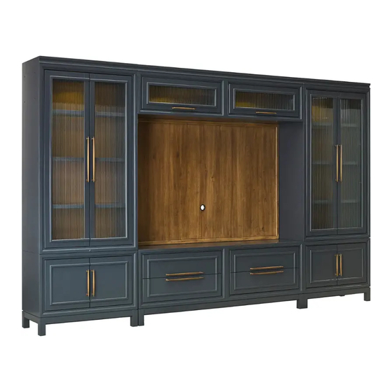
ITEM NO: I3014-272B
I3014-273
Thank you for purchasing this quality product. Be sure to check all packing material carefully for
small parts that may come loose inside the carton during shipment.
COMPONENTS LIST:
Description
No.
1
Backer
COMPONENTS LIST:
Description
No.
1
Bridge
2
Metal Hook
FUNCTIONALITY INSTRUCTION
WARNING! Before using this product, please read, understand, and follow these instructions. Failure to follow
each of these assembly instructions precisely may result in damage to the product and / or injury to the consumer.
Page 1/3
72" Backer
72" Bridge
UNIT SHOULD BE INSTALLED BY 2 OR MORE PERSONS.
I3014-273
I3014-272B
I3014-272B
Quantity
Sketch
1 PC
I3014-273
Quantity
Sketch
1 PC
2 PCS
Touch Switch
Ensure support leg makes
proper contact with the
ground by adjusting leveler.
FOR INDOOR USE ONLY
MADE IN VIETNAM
ASSEMBLY INSTRUCTIONS
R
TOOLS REQUIRED (NOT PROVIDED)
PHILLIPS SCREWDRIVER
HARDWARE LIST:
No.
Description
Bolt Ø1/4" x 3/4"
A
Bolt Ø1/4" x 2-1/4"
B
Lock Washer Ø1/4"
C
Flat Washer Ø1/4" x 3/4"
D
Allen Wrench 4mm
E
Metal Plate
F
HARDWARE LIST:
No.
Description
G Wood Screw #3.5 x 5/8"
Hex Bolt Ø1/4" x 1"
H
Female Bolt Ø1/4"x13/16"
I
Allen Wrench 4mm
J
I3014-272B
Sketch
I3014-273
Sketch
Touch Switch
Touch the touch switch to turn
on/off or adjust the lighting.
Adjust the leveler
when necessary
Leveler on legs
Quantity
16 PCS
3 PCS
19 PCS
19 PCS
1 PCS
4 PCS
Quantity
10 PCS
8 PCS
8 PCS
2 PCS
01-05-2024
Advertisement

Related Manuals for aspenhome I3014-272B


Summary of Contents for aspenhome I3014-272B
- Page 1 ASSEMBLY INSTRUCTIONS ITEM NO: I3014-272B 72" Backer I3014-273 72" Bridge Thank you for purchasing this quality product. Be sure to check all packing material carefully for small parts that may come loose inside the carton during shipment. UNIT SHOULD BE INSTALLED BY 2 OR MORE PERSONS.
- Page 2 ASSEMBLY INSTRUCTIONS ITEM NO: I3014-272B 72" Backer I3014-273 72" Bridge STEP 1: Align the side piers to the console as shown below. Pier Pier Console STEP 2: Attach the backer above the console and between side piers by using 16 bolts (A), lock washers (C), flat washers (D) with 4 metal plates (F) as shown below.
- Page 3 ASSEMBLY INSTRUCTIONS ITEM NO: I3014-272B 72" Backer I3014-273 72" Bridge STEP 3: Attach the metal hooks to the bridge with wood screws (G) as shown below. STEP 4: Reverse the handles by removing the screws while each door is open and attach the handles to the front of the door with screws as shown below.
Need help?
Do you have a question about the I3014-272B and is the answer not in the manual?
Questions and answers