Advertisement
Quick Links
INSTRUCTION MANUAL
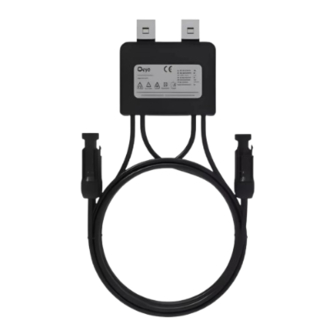
PHOTOVOLTAIC SMART OPTIMIZER
TECHNICAL DATA
MODEL
SKU
MAX. INPUT/OUTPUT POWER(DC)
MAX. INPUT/OUTPUT VOLTAGE(DC)
MPPT VOLTAGE RANGE(DC)
MAX. INPUT/OUTPUT CURRENT(DC)
PEAK CONVERSION EFFICIENCY
OPERATING TEMPERATURE
INTRODUCTION & WARRANTY
Thank you for selecting and buying V-TAC product. V-TAC will serve you the best. Please
read these instructions carefully before starting the installation and keep this manual handy
for future reference. If you have any another query, please contact our dealer or local
vendor from whom you have purchased the product. They are trained and ready to serve
you at the best. The warranty is valid for 10 years from the date of purchase. The warranty
does not apply to damage caused by incorrect installation or abnormal wear and tear. The
company gives no warranty against damage to any surface due to incorrect removal and
installation of the product. This product is warranted for manufacturing defects only.
This marking indicates that this
product should not be disposed
of with other household wastes.
MULTI-LANGUAGE
MANUAL QR CODE
Please scan the QR code
to access the manual in
multiple languages.
In case of any query/issue with the product, please reach out to us at: support@v-tac.eu
For More products range, inquiry please contact our distributor or nearest dealers.
SUN-XL02-A
11946
700W
80V
12-80V
15A
99.5%
-40°C to +85°C
V-TAC EUROPE LTD. Bulgaria, Plovdiv 4000, bul.L.Karavelow 9B
Caution, Risk of electric shock
Advertisement

Summary of Contents for V-TAC Deye SUN-XL02-A
- Page 1 -40°C to +85°C INTRODUCTION & WARRANTY Thank you for selecting and buying V-TAC product. V-TAC will serve you the best. Please read these instructions carefully before starting the installation and keep this manual handy for future reference. If you have any another query, please contact our dealer or local vendor from whom you have purchased the product.
-
Page 2: Safety Instructions
WARNING 1. Please make sure to turn off the power before starting the installation. 2. Installation must be performed by a qualified electrician. DANGER “Danger” indicates a situation that has a high potential risk and will result in death or serious injury if not avoided. - Page 3 2.2 COMPOSITION OF PHOTOVOLTAIC SYSTEM photovoltaic system is that each photovoltaic module is installed with an external optimizer to achieve module-level MPPT. The input of external optimizer is connected to output of module. The output of optimizer are connected to each other, which is merged into later stage inverter or com- biner box.
- Page 4 Clip PV Module Frame Picture 1 Picture 2 Picture 3 • Step 3. Connection of input line The line marked with “IN” on the housing of external optimizer is the input line, which is connected to the output line of module.` WARNING When installing, connect the input line of optimizer first, then connect the output line. When remov- ing, disconnect the output line first, then disconnect the input line.
- Page 5 • Step 6. Turn on the inverter After confirming that the system is connected correctly, turn on the inverter. • 4. Check and Replacement WARNING The following operations must be completed by trained professional technicians to avoid the risk of electric shock. 4.1 CHECK Check whether the optimizer is abnormal by following the steps below: • 1. To check whether the external optimizer is operated normally, measure the input current of optimizer with clip-on ammeter.
- Page 6 5. INSTRUCTIONS TO APPLICABLE SCENE The external optimizer is suitable for various types of power stations, distributed and large-scale surface power stations; new power stations, reconstructive old power stations. In consideration of various mismatch situations, the installation methods are as follows. 5.1 ONE MPPT PORT WITH ONE STRING 5.1.1 FULL INSTALLATION The photovoltaic system has various mismatches, such as shadow shading, inconsistent orientation,...
- Page 7 Risk of installation on mismatched module only: The mismatch of other modules cannot be solved. When the judgment of system mismatch is not accurate, for example,some modules are seriously mismatched due to damage while there is no obvious mismatch on the surface, because the optimizer is not installed, this module will cause great loss to the power generation of system.
-
Page 8: Product Specification
5.2.3 INSTALLATION OF MISMATCHED MODULE When only part of modules in an array has clear mismatch, it is allowed to only install the modules with clear mismatch. In this way, the mismatch can be solved to a large extent at the lowest cost, so as to recover losses of power generation. -
Page 9: Eu Declaration Of Conformity
EU DECLARATION OF CONFORMITY within the scope of the EU directives · Radio Equipment Directive 2014/53/EU (RED) · Restriction of the use of certain hazardous substances 2011/65/EU)(RoHS) NINGBO DEYE INVERTER TECHNOLOGY CO.,LTD. confirms herewith that the products described in this document are in compliance with the fundamental requirements and other relevant provisions of the above mentioned directives.


Need help?
Do you have a question about the Deye SUN-XL02-A and is the answer not in the manual?
Questions and answers