Table of Contents
Advertisement
Quick Links
Advertisement
Table of Contents

Related Manuals for Daikin BEV2N112ACV1B


Summary of Contents for Daikin BEV2N112ACV1B
- Page 1 Installer reference guide CO₂ Conveni-Pack: BEV2 unit BEV2N112ACV1B...
-
Page 2: Table Of Contents
Table of contents Table of contents 1 About the documentation About this document ..............................2 General safety precautions About the documentation .............................. 2.1.1 Meaning of warnings and symbols ........................ For the installer ................................2.2.1 General ................................2.2.2 Installation site ............................... 2.2.3 Refrigerant —... -
Page 3: About The Documentation
▪ A subset of the latest technical data is available on the regional Daikin website (publicly accessible). ▪ The full set of the latest technical data is available on the Daikin Business Portal (authentication required). BEV2N-A Installer reference guide CO₂ Conveni-Pack: BEV2 unit... -
Page 4: General Safety Precautions
General safety precautions 2 General safety precautions 2.1 About the documentation ▪ The original instructions are written in English. All other languages are translations of the original instructions. ▪ The precautions described in this document cover very important topics, follow them carefully. -
Page 5: For The Installer
WARNING Improper installation or attachment of equipment or accessories could result in electrical shock, short-circuit, leaks, fire or other damage to the equipment. ONLY use accessories, optional equipment and spare parts made or approved by Daikin unless otherwise specified. WARNING Make sure installation, testing and applied materials comply with applicable legislation (on top of the instructions described in the Daikin documentation). -
Page 6: Installation Site
General safety precautions CAUTION Wear adequate personal protective equipment (protective gloves, safety glasses,…) when installing, maintaining or servicing the system. CAUTION Do NOT touch the air inlet or aluminium fins of the unit. CAUTION ▪ Do NOT place any objects or equipment on top of the unit. ▪... - Page 7 General safety precautions NOTICE Make sure the field piping and connections are NOT subjected to stress. WARNING During tests, NEVER pressurise the product with a pressure higher than the maximum allowable pressure (as indicated on the nameplate of the unit). WARNING Take sufficient precautions in case of refrigerant leakage.
-
Page 8: Electrical
General safety precautions CAUTION When the refrigerant charging procedure is done or when pausing, close the valve of the refrigerant tank immediately. If the valve is NOT closed immediately, remaining pressure might charge additional refrigerant. Possible consequence: Incorrect refrigerant amount. 2.2.4 Electrical DANGER: RISK OF ELECTROCUTION ▪... - Page 9 General safety precautions CAUTION ▪ When connecting the power supply: connect the earth cable first, before making the current-carrying connections. ▪ When disconnecting the power supply: disconnect the current-carrying cables first, before separating the earth connection. ▪ The length of the conductors between the power supply stress relief and the terminal block itself MUST be as such that the current-carrying wires are tautened before the earth wire is in case the power supply is pulled loose from the stress relief.
-
Page 10: Specific Installer Safety Instructions
WARNING Make sure installation, servicing, maintenance, repair and applied materials follow the instructions from Daikin (including all documents listed in “Documentation set”) and, in addition, comply with applicable legislation and are performed by qualified persons only. In Europe and areas where IEC standards apply, EN/IEC 60335-2-40 is the applicable standard. - Page 11 Specific installer safety instructions CAUTION NEVER bend high pressure piping! Bending can reduce the pipe thickness and thus weaken the piping. ALWAYS use K65 fittings. Electrical installation (see "8 Electrical installation" [ 27]) WARNING ALWAYS use multicore cable for power supply cables. WARNING ▪...
- Page 12 Specific installer safety instructions Symbol Explanation Measure the voltage at the terminals of main circuit capacitors or electrical components before servicing. Commissioning (see "9 Commissioning" [ 33]) WARNING Make sure that the service cover is closed after completing the installation of the indoor unit, BEV2 unit, and outdoor unit.
-
Page 13: About The Box
About the box 4 About the box NOTICE Before installation, check the packaging and parts for damage. Make sure that the shipment is complete. Keep the following in mind: ▪ At delivery, the unit MUST be checked for damage and completeness. Any damage or missing parts MUST be reported immediately to the claims agent of the carrier. -
Page 14: About The Unit
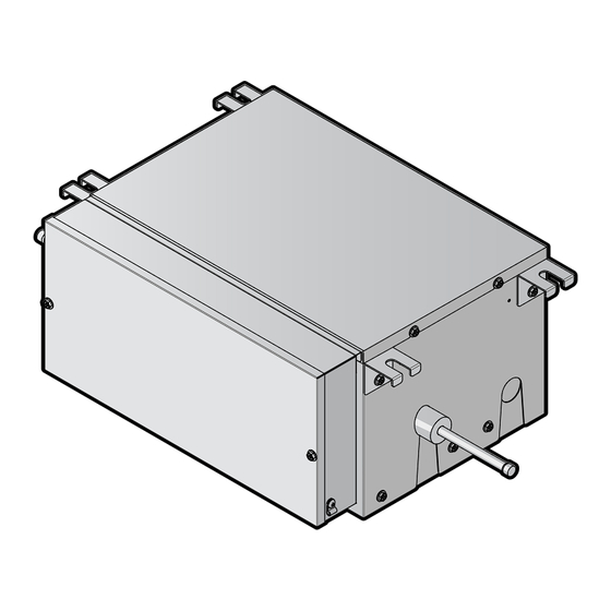
About the unit 5 About the unit INFORMATION The BEV2 unit is an extension for the indoor unit containing external expansion valves. It is mandatory for some units using CO2 refrigerant; see the Daikin catalogue for combinations. 5.1 System layout INFORMATION... -
Page 15: Compatibility
About the unit INFORMATION ▪ The maximum installation distance between the indoor unit and the BEV2 unit depends on the length of the included transmission and power supply cables. ▪ Make sure to install the units so the cables reach both units terminals. ▪... -
Page 16: Unit Installation
Unit installation 6 Unit installation WARNING ▪ Installation shall be done by an installer, the choice of materials and installation shall comply with the applicable legislation. In Europe, EN378 is the applicable standard. ▪ Make sure to install all necessary countermeasures in case of refrigerant leakage according to standard EN378 (see "6.1.2 Additional installation site requirements for CO₂... - Page 17 Unit installation CAUTION Appliance NOT accessible to the general public, install it in a secured area, protected from easy access. This unit, both indoor and outdoor, is suitable for installation in a commercial and light industrial environment. NOTICE ▪ The professional installer shall evaluate the EMC situation before installation, if the equipment is installed closer than 30 m to a residential location.
-
Page 18: Additional Installation Site Requirements For Co₂ Refrigerant
Unit installation ≥250 ≥250 (mm) a Outdoor unit side b Indoor units side ▪ Service space. Be sure to install the inspection door at the control box side. (mm) a Control box b Service space c Inspection door INFORMATION ▪ The maximum installation distance between the indoor unit and the BEV2 unit depends on the length of the included transmission and power supply cables. -
Page 19: To Mount The Unit
Unit installation TO ODU TO IDU TO ODU Install this side facing to outdoor unit TO IDU Install this side facing to indoor unit ▪ Suspension bolts and unit. Use M8~M10 suspension bolts for installation. Attach the hanger bracket to the suspension bolt. Fix it securely using a nut and washer on the top and bottom of the hanger bracket. - Page 20 Unit installation 3, 8 180° 4, 7 a Control box lid b Control box c Top panel d Coil cover e Wire clip f Tie wrap 1 Remove the control box lid (2 screws). 2 Remove the control box (2 screws). 3 Remove the top panel (4 screws).
- Page 21 Unit installation c Hanger bracket d Suspension bolt (field supply) e Unit BEV2N-A Installer reference guide CO₂ Conveni-Pack: BEV2 unit 4P677928-1B – 2023.11...
-
Page 22: Piping Installation
Piping installation 7 Piping installation In this chapter Preparing refrigerant piping ..............................7.1.1 Refrigerant piping requirements ........................... 7.1.2 Refrigerant piping insulation..........................Connecting the refrigerant piping............................7.2.1 About connecting the refrigerant piping....................... 7.2.2 Precautions when connecting the refrigerant piping.................... 7.2.3 Guidelines when connecting the refrigerant piping....................7.2.4 To connect the refrigerant piping to the indoor unit.................... -
Page 23: Refrigerant Piping Insulation
Piping installation Refrigerant piping diameter Pipe outer diameter (mm) 2× Ø9.5 Refrigerant piping material ▪ Piping material: K65 copper-iron alloy (CuFe2P), maximum operating pressure = 120 bar ▪ Piping temper grade and thickness: Outer diameter (Ø) Temper grade Thickness (t) Ø 9.5 mm (3/8") R420 ≥0.65 mm... -
Page 24: Precautions When Connecting The Refrigerant Piping
Piping installation ▪ Keeping in mind the guidelines for: Pipe bending Brazing Using the stop valves 7.2.2 Precautions when connecting the refrigerant piping INFORMATION Also read the precautions and requirements in the following chapters: ▪ "2 General safety precautions" [ 4] ▪ "7.1 Preparing refrigerant piping" [ 22]... -
Page 25: Guidelines When Connecting The Refrigerant Piping
Piping installation 7.2.3 Guidelines when connecting the refrigerant piping ▪ When brazing, blow through with nitrogen to prevent creation of large quantities of oxidized film on the inside of the piping. This film adversely affects valves and compressors in the refrigerating system and prevents proper operation. ▪... - Page 26 Piping installation WARNING ▪ Use K65 piping for high-pressure applications with a working gauge pressure of 120 bar or 90 bar, depending on its location in the system. ▪ Use K65 unions and fittings approved for a working gauge pressure of 120 bar or 90 bar, depending on its location in the system.
-
Page 27: Electrical Installation
Electrical installation 8 Electrical installation NOTICE This is a class A product. In a domestic environment this product may cause radio interference in which case the user may be required to take adequate measures. In this chapter About connecting the electrical wiring ..........................8.1.1 Precautions when connecting the electrical wiring .................... -
Page 28: Guidelines When Connecting The Electrical Wiring
Electrical installation WARNING ▪ If the power supply has a missing or wrong N-phase, equipment might break down. ▪ Establish proper earthing. Do NOT earth the unit to a utility pipe, surge absorber, or telephone earth. Incomplete earthing may cause electrical shocks. ▪... - Page 29 Electrical installation Method 2: Using round crimp-style terminal 1 Strip insulation from wires and slightly twist the end of each wire. 2 Install a round crimp-style terminal on the end of the wire. Place the round crimp-style terminal on the wire up to the covered part and fasten the terminal with the appropriate tool.
-
Page 30: To Connect The Electrical Wiring To The Bev2 Unit
Electrical installation Tightening torques Wiring Screw size Tightening torque (N•m) Power supply cable 1.18~1.44 Earth terminal cable 1.52~1.86 ▪ The earth wire between the wire retainer and the terminal must be longer than the other wires. 8.2 To connect the electrical wiring to the BEV2 unit NOTICE ▪... - Page 31 Electrical installation Connection to the indoor unit X70A a Transmission cable feed-through hole b Transmission cable (indoor unit accessory) c Jumper d X70A connector e Faston connector f Power supply feed-through hole g Power supply cable Connection to the BEV2 unit a Transmission cable b Power supply cable c Tie wrap (accessory)
- Page 32 Electrical installation a Outdoor unit control box b Indoor unit c BEV2 unit d User interface BEV2N-A Installer reference guide CO₂ Conveni-Pack: BEV2 unit 4P677928-1B – 2023.11...
-
Page 33: Commissioning
Commissioning 9 Commissioning WARNING Make sure that the service cover is closed after completing the installation of the indoor unit, BEV2 unit, and outdoor unit. INFORMATION Refer to the installation manuals provided with the indoor and outdoor units for the commissioning of the system. -
Page 34: Disposal
Disposal 10 Disposal NOTICE Do NOT try to dismantle the system yourself: dismantling of the system, treatment of the refrigerant, oil and other parts MUST comply with applicable legislation. Units MUST be treated at a specialised treatment facility for reuse, recycling and recovery. BEV2N-A Installer reference guide CO₂... -
Page 35: Technical Data
A subset of the latest technical data is available on the regional Daikin website (publicly accessible). ▪ The full set of the latest technical data is available on the Daikin Business Portal (authentication required). 11.1 Wiring diagram 11.1.1 Unified wiring diagram legend For applied parts and numbering, refer to the wiring diagram on the unit. - Page 36 Technical data Symbol Meaning AC*, CN*, E*, HA*, HE*, HL*, HN*, HR*, Connection, connector MR*_A, MR*_B, S*, U, V, W, X*A, K*R_*, NE D*, V*D Diode Diode bridge DIP switch Heater FU*, F*U, (for characteristics, refer to Fuse PCB inside your unit) Connector (frame ground) Harness H*P, LED*, V*L...
- Page 37 Technical data Symbol Meaning Thermo switch Residual current device Resistor Thermistor Receiver Limit switch Float switch S*NG Refrigerant leak detector S*NPH Pressure sensor (high) S*NPL Pressure sensor (low) S*PH, HPS* Pressure switch (high) S*PL Pressure switch (low) Thermostat S*RH Humidity sensor S*W, SW* Operation switch SA*, F1S...
-
Page 38: Glossary
Optional equipment Equipment made or approved by Daikin that can be combined with the product according to the instructions in the accompanying documentation. Field supply Equipment NOT made by Daikin that can be combined with the product according to the instructions in the accompanying documentation. - Page 40 4P677928-1B 2023.11 Verantwortung für Energie und Umwelt...
Need help?
Do you have a question about the BEV2N112ACV1B and is the answer not in the manual?
Questions and answers