Table of Contents
Advertisement
Quick Links
Advertisement
Table of Contents

Related Manuals for Panasonic KV-S7065C Series


Summary of Contents for Panasonic KV-S7065C Series
- Page 1 Service Manual TOP NEXT Order Number KM70401905C0 Category Number G14 High Speed Color Scanner KV-S7065CSERIES © 2004 Panasonic Communications Co., Ltd. All rights reserved. Unauthorized copying and distribution is a violation of law. TOP NEXT...
- Page 2 Table Of Contents COVER 1 GENERAL PRECAUTIONS 1.1 Safety Precautions 1.2 Electrical Tests 1.3 For Service Technicians 1.4 About Lead Free Solder (PbF: Pb free) 1.4.1 Suggested Pb free solder 2 SPECIFICATIONS 3 COMPONENT IDENTIFICATION 4 INSTALLATION 4.1 Minimum Space Requirements 4.2 Installing Hopper Tray 4.3 DIMM Module Extension 4.4 Installing DIMM Module...
- Page 3 4.7 System Requirements 5 SECTIONAL VIEWS 5.1 CIS (Contact Image Sensor) 5.2 Rollers 5.3 Drive Belts 5.4 Boards 5.4.1 ADF Block 5.4.2 Flatbed Block and others 6 MECHANICAL FUNCTION 6.1 Paper Feed Mechanism (Auto) 6.2 Paper Feed Mechanism (Manual) 6.3 Paper Feed Roller / Hopper Lift Drive Mechanism 6.4 Hopper Lift Mechanism 6.5 Carriage Drive Mechanism 7 MAINTENANCE...
- Page 4 7.2.5 Cleaning Sensors and Reflector Sheets-1 (Paper and Waiting Sensors, Double Feed Detector) 7.2.6 Cleaning Sensors and Reflector Sheets-2 (Starting, Skew (L), Skew (R), and Ending Sensors) 7.2.7 Cleaning Flatbed Glass 7.3 Replacing Limited Life Parts 7.3.1 Replacing Paper Feed Roller Module 7.3.2 Replacing Retard Roller 8 DISASSEMBLY INSTRUCTIONS 8.1 Disassembly Flowchart...
- Page 5 8.2.9 Side Cover (L) 8.2.10 Side Cover (R) 8.2.11 Flatbed Glass 8.2.12 CARRIAGE HOME DETECTOR Board 8.2.13 Shield Plates (A, B) 8.2.14 CONTROL Board 8.2.15 DRIVE Board 8.2.16 Carriage Motor 8.2.17 Power Box & Cover 8.2.18 FAN 8.2.19 POWER Board 8.2.20 Inverter Cover 8.2.21 CIS (F) 8.2.22 CARRIAGE RELAY Board...
- Page 6 8.3.6 Top Cover 8.3.7 WAITING SENSOR Board 8.3.8 Hopper Tray 8.3.9 Hopper 8.3.10 SIZE DETECTOR Board 8.3.11 Paper Sensor 8.3.12 ADF Cover (F) 8.3.13 SENSOR RELAY Board 8.3.14 ADF Cover (B) 8.3.15 ADF Door Switch 8.3.16 POWER RELAY Board 8.3.17 Conveyor 1 8.3.18 Drive Belts 1, 2, 3 8.3.19 Drive Rollers 1, 2, 3 8.3.20 Double Feed Detector (G)
- Page 7 8.3.26 Hopper Base 8.3.27 HOPPER HOME DETECTOR Board 8.3.28 Retard Conveyor 8.3.29 HOPPER RELAY Board 8.3.30 Exit Conveyor 8.3.31 Exit Roller 8.3.32 ENDING SENSOR Board 8.3.33 Exit Door Switch 8.3.34 CIS (B) & CIS RELAY Board 8.3.35 Lamp Drive (B) Board 8.3.36 Paper Feed Motor 8.3.37 Conveyor Motor 9 SERVICE UTILITY &...
- Page 8 9.3.6 Test 9.3.7 Adjust 9.3.8 Other (Serial NO., Save Information) 9.4 Scanner Self-test 10 TROUBLESHOOTING 10.1 Troubleshooting-1 (with no error message on PC) 10.2 Troubleshooting-2 (According to error message on PC) 10.2.1 Error Code 10.3 Requirement After Parts Replacement 11 CIRCUIT DESCRIPTION 11.1 Block Diagram-1 (Image Processing) 11.2 Block Diagram-2 (Board) 11.3 Explanation of Connector...
- Page 9 12.3 DRIVE Board 12.4 CARRIAGE RELAY Board 12.4.1 Front Side 12.4.2 Back Side 12.5 CIS RELAY Board 12.5.1 Front Side 12.5.2 Back Side 12.6 OUTER CONVEYOR RELAY Board 12.7 WAITING SENSOR Board 12.8 ENDING SENSOR Board 12.9 HOPPER HOME DETECTOR Board 12.10 SIZE DETECTOR Board 12.11 STARTING SENSOR Board 12.12 HOPPER RELAY Board...
- Page 10 13.1 CONTROL Board 13.2 INTERFACE Board 13.3 DRIVE Board 13.4 CARRIAGE RELAY and CIS RELAY Boards 13.5 RELAY, SENSOR, and PANEL Boards 13.6 POWER Board 14 PARTS LOCATION AND MECHANICAL PARTS LIST 14.1 Exterior 14.2 ADF (Outer) 14.3 ADF (Inner) 14.4 Flatbed 14.5 Board Assembly &...
- Page 11 15.6 OUTER CONVEYOR RELAY Board 15.7 WAITING SENSOR Board 15.8 ENDING SENSOR Board 15.9 HOPPER HOME DETECTOR Board 15.10 SIZE DETECTOR Board 15.11 STARTING SENSOR Board 15.12 HOPPER RELAY Board 15.13 SENSOR RELAY Board 15.14 POWER RELAY Board 15.15 PANEL Board 15.16 DOCUMENT COVER DETECTOR Board 15.17 CARRIAGE HOME DETECTOR Board 15.18 POWER Board...
- Page 12 1 GENERAL PRECAUTIONS TOP PREVIOUS NEXT 1.1 Safety Precautions 1.2 Electrical Tests 1.3 For Service Technicians 1.4 About Lead Free Solder (PbF: Pb free) 1.4.1 Suggested Pb free solder TOP PREVIOUS NEXT...
- Page 13 1.1 Safety Precautions TOP PREVIOUS NEXT 1. Before servicing, unplug the power cord to prevent electrical shock hazard. 2. When replacing parts, user only manufactures recommended components for safety. 3. Check the condition of power cord. Replace if wear or damage is evident. 4.
- Page 14 1.2 Electrical Tests TOP PREVIOUS NEXT 1. Unplug the power cord and check for continuity between the earth ground connection on the plug and the metal cabinet. There should be zero ohm resistance found. 2. With the unit unplugged, short the AC Live-Neutral of the plug with a jumper wire. 3.
- Page 15 TOP PREVIOUS NEXT...
- Page 16 1.3 For Service Technicians TOP PREVIOUS NEXT ICs and LSIs are vulnerable to static electricity. When repairing, the following precautions will help to prevent recurring malfunctions. 1. Cover the plastic parts with aluminum foil. 2. Ground the soldering irons. 3. Use a conductive mat on the worktable. 4.
- Page 17 1.4 About Lead Free Solder (PbF: Pb free) TOP PREVIOUS NEXT Note In the information below, Pb, the symbol for lead in the periodic table of elements, will refer to standard solder or solder that contains lead. We will use PbF when discussing the lead free solder used in our manufacturing process which is made from Tin (Sn), Silver (Ag), and Copper (Cu). This model, and others like it, manufactured using lead free solder will have PbF stamped on the PCB.
- Page 18 1.4.1 Suggested Pb free solder TOP PREVIOUS NEXT...
- Page 19 1.4.1 Suggested Pb free solder TOP PREVIOUS NEXT We recommend you to use the following solder when you re-solder components for repair. Before using other Pb free solder than the following solder, be sure to confirm a solder maker you appoint has made license agreements to be required when usingPb free solder legally.
- Page 20 2 SPECIFICATIONS TOP PREVIOUS NEXT Item Model No. KV-S7065C Series*1 Scanner Scanning face Duplex Scanning method CIS (Contact-type color Image Sensor): Front & Back sides and Flatbed Background: Black / White (switchable) Readout Speed Flatbed 0.704 s (Letter, 200 dpi), 0.320 ms/line Black &...
- Page 21 DETECTOR, OUTER CONVEYOR RELAY, STARTING SENSOR, WAITINGSENSOR, ENDING SENSOR, CARRIAGE RELAY, SENSOR RELAY, POWER RELAY, and CIS RELAY Boards for KV-S7065C Series. Note: Distinction of PbF PCB PCBs (manufactured) using lead free solder will have a PbF stamp on the PCB.
- Page 22 SERIAL No. for U.S.A. and Canada 723 xxxx xxxx SERIAL No. for Europe 732 xxxx xxxx SERIAL No. for Australia 733 xxxx xxxx SERIAL No. for Taiwan 734 xxxx xxxx (x: Dont care) KX-S7065CCN : for China SERIAL No. for China 735 xxxx xxxx (x: Dont care) *2For KV-S7065C/S7065C-T...
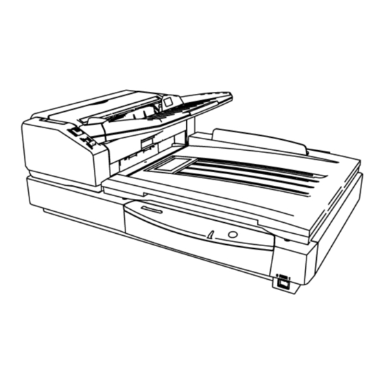
- Page 23 3 COMPONENT IDENTIFICATION TOP PREVIOUS NEXT...
- Page 24 Power Indicator: for showing scanner status Color Flashing Green 1. Ready Sleeping 2. Scanning Orange *1. Ready with warning 1. Initializing *2. Scanning with warning *2. Sleeping with warning 3. Shading An error System error Note: *Warning error: Clean roller or replace roller...
- Page 27 TOP PREVIOUS NEXT...
- Page 28 4 INSTALLATION TOP PREVIOUS NEXT 4.1 Minimum Space Requirements 4.2 Installing Hopper Tray 4.3 DIMM Module Extension 4.4 Installing DIMM Module 4.5 Setting 4.5.1 SCSI 4.6 Connecting the Scanner to a Personal Computer 4.6.1 SCSI connection 4.6.2 USB Connection 4.7 System Requirements TOP PREVIOUS NEXT...
- Page 29 4.1 Minimum Space Requirements TOP PREVIOUS NEXT Be sure to maintain the recommended space requirements for proper ventilation. Fig. 4.1.1 Dimensions for proper ventilation...
- Page 30 TOP PREVIOUS NEXT...
- Page 31 4.2 Installing Hopper Tray TOP PREVIOUS NEXT Take out the Hopper tray in the accessory carton box, and hang the tip of the tray to one side at first. And hang the other side tip of the tray in the direction of the arrow (2), pushing it the direction of the arrow (1) to attach it.
- Page 32 TOP PREVIOUS NEXT...
- Page 33 4.3 DIMM Module Extension TOP PREVIOUS NEXT A maximum of 512MB extended memory may be required depending on the combination of the paper size, mode, and resolution. To determine how much extended memory is required on each condition, refer to Fig.4.3.1 and Fig.4.3.2.
- Page 34 8 bit Gray *1 SCs Max Double Letter Legal Letter 24 bit Color *1 SCs Max 64 128 256 256 Double Letter 64 128 256 Legal Letter 64 128 256 64 128 Fig.4.3.2 Additional memory size-2 (Duplex) (Unit: MB) *1 : 297×635 mm (11.7×25.0) Mode Size 100 200 300 400 500 600...
- Page 35 Double Letter Legal Letter 8 bit Gray 64 128 256 *1 SCs Max Double Letter 64 128 Legal Letter 64 128 24 bit Color *1 SCs Max 64 128 256 512 Double Letter 64 128 256 512 Legal 64 128 256 Letter 64 128 256 64 128 256 512...
- Page 36 4.4 Installing DIMM Module TOP PREVIOUS NEXT 1. Remove INTERFACE Board. (See 8.2.8.) 2. Insert the DIMM Module into connector (CN2007) on the INTERFACE Board, and raise the tabs at the both ends of the connector until they lock into place. TOP PREVIOUS NEXT...
- Page 37 4.5 Setting TOP PREVIOUS NEXT 4.5.1 SCSI TOP PREVIOUS NEXT...
- Page 38 4.5.1 SCSI TOP PREVIOUS NEXT When connecting this scanner to PC via SCSI interface, perform the SCSI ID setting as follows. SCSI ID Setting ID No. Switch Remarks #2 #1 #0 Factory Default...
- Page 39 TOP PREVIOUS NEXT...
- Page 40 4.6 Connecting the Scanner to a Personal Computer TOP PREVIOUS NEXT Connect either USB or SCSI interface cable at a time. Note: Windows NT supports only SCSI interface. 4.6.1 SCSI connection 4.6.2 USB Connection TOP PREVIOUS NEXT...
- Page 41 4.6.1 SCSI connection TOP PREVIOUS NEXT Fig.4.6.1 Note: Power Cord shown on the Fig.4.6.1 is for AC100-120 V. Caution: Use the Power Cord that is supplied by the scanner manufacturer. Use SCSI cables as short as possible, securing SCSI specification.
- Page 42 After turning off the scanner and PC, remove SCSI cables. TOP PREVIOUS NEXT...
- Page 43 4.6.2 USB Connection TOP PREVIOUS NEXT Fig.4.6.2 Note: Power Cord shown on the Fig.4.6.2 is for AC100 V-120 V. Caution: Use the Power Cord that is supplied by the scanner manufacturer. Use a USB interface cable that is certified as Hi-Speed logo by USB-IF.
- Page 44 TOP PREVIOUS NEXT...
- Page 45 4.7 System Requirements TOP PREVIOUS NEXT When using the scanner, the required personal computer conditions are as follows. SCSI Connection USB Connection Minimum: Pentium , 1 GHz Recommended: Pentium 4, 2 GHz or higher Memory Minimum: 256MB Recommended: 512MB or more Windows®...
- Page 46 When using Windows NT, be sure to install the ASPI layer software that the SCSI Boards vender provides. Note 2: Windows® 98 is Microsoft® Windows® 98 operating system. Windows® Me is Microsoft® Windows® Me operating system. Windows NT® is Microsoft® Windows NT® operating system. Windows®...
- Page 47 5 SECTIONAL VIEWS TOP PREVIOUS NEXT 5.1 CIS (Contact Image Sensor) 5.2 Rollers 5.3 Drive Belts 5.4 Boards 5.4.1 ADF Block 5.4.2 Flatbed Block and others TOP PREVIOUS NEXT...
- Page 48 5.1 CIS (Contact Image Sensor) TOP PREVIOUS NEXT TOP PREVIOUS NEXT...
- Page 49 5.2 Rollers TOP PREVIOUS NEXT TOP PREVIOUS NEXT...
- Page 50 5.3 Drive Belts TOP PREVIOUS NEXT TOP PREVIOUS NEXT...
- Page 51 5.4 Boards TOP PREVIOUS NEXT 5.4.1 ADF Block 5.4.2 Flatbed Block and others TOP PREVIOUS NEXT...
- Page 52 5.4.1 ADF Block TOP PREVIOUS NEXT TOP PREVIOUS NEXT...
- Page 53 5.4.2 Flatbed Block and others TOP PREVIOUS NEXT Note: *1CARRIAGE HOME DETECTOR Board is not included in the CIS Carriage, but is located under the carriage. TOP PREVIOUS NEXT...
- Page 54 6 MECHANICAL FUNCTION TOP PREVIOUS NEXT 6.1 Paper Feed Mechanism (Auto) 6.2 Paper Feed Mechanism (Manual) 6.3 Paper Feed Roller / Hopper Lift Drive Mechanism 6.4 Hopper Lift Mechanism 6.5 Carriage Drive Mechanism TOP PREVIOUS NEXT...
- Page 55 6.1 Paper Feed Mechanism (Auto) TOP PREVIOUS NEXT Fig.6.1 1. When the paper is set on the Hopper, and the scanning command is issued from PC, the Hopper rises and the paper will be brought into contact with Paper Feed Roller.
- Page 56 3. When the Paper Feed Motor starts, the Paper Feed Roller and the Separation Roller turn in feed direction. The Retard Roller is supported by shaft fixed via a torque limiter, and it is pushed against the Separation Roller. When the document enters into the separation section, the Retard Roller exerts a manipulation force onto the document, which depends on the set torque. In case of continuous paper feed, the document is separated by this manipulation force and is fed to the scanning section.
- Page 57 6.2 Paper Feed Mechanism (Manual) TOP PREVIOUS NEXT Fig.6.2 For multiple sheets scanning, there is possibility that the first page and second page will be separated, and the paper will be torn if paper is scanned while the Retard Roller is locked.
- Page 58 6.3 Paper Feed Roller/ Hopper Lift Drive Mechanism TOP PREVIOUS NEXT Fig.6.3 Paper Feed Motor drives either Paper Feed Roller mechanism or Hopper lift mechanism by selecting the direction of rotation. The drive system is shown on Fig.6.3. (a) The gear train (1) belongs to drive system for Paper Feed Roller and Separation roller. (b) The gear train (2) belongs to drive system for Hopper Lift.
- Page 59 When the Paper Feed Motor drives in the direction of arrow A, Paper Feed Roller is activated, based on output axis. On the other hand, when the Paper Feed Motor drives in the direction of arrow B, Hopper Lift mechanism is activated. Gears marked with (*) on Each Gear train have one way clutches.
- Page 60 6.4 Hopper Lift Mechanism TOP PREVIOUS NEXT 1. Hopper is mounted on Lift Roller of Hopper Lift Arm. 2. Hopper Lift Arm is supported by Hopper Cam through Hopper Spring.
- Page 61 3. Hopper Cam is an eccentric type cam, and is connected to Hopper Lift Gear Train (Gear Train (2)) mentioned in Fig.6.3. 4. When Hopper cam is in condition as shown in Fig.6.4.2, the paper can be set. 5. When the Hopper cam rotates in the direction of arrow as shown in Fig.6.4.3, it pushes up Hopper Spring, and enables paper to be fed by attaching Hopper to Paper Feed Roller.
- Page 62 6.5 Carriage Drive Mechanism TOP PREVIOUS NEXT 1. When the paper is set on the Flatbed Glass, and the scanning command is issued from PC, the Carriage Motor rotates to drive the CIS Carriage. 2. After scanning the defined size, the Carriage Motor rotates in reverse, and the CIS Carriage returns to its home position. TOP PREVIOUS NEXT...
- Page 63 7 MAINTENANCE TOP PREVIOUS NEXT 7.1 Maintenance Chart 7.2 Cleaning 7.2.1 Cleaning Rollers-1 (Paper Feed, Separation, and Retard Rollers) 7.2.2 Cleaning Roller-2 (Drive Rollers 1, 2 and Free Rollers) 7.2.3 Cleaning Roller-3 (Drive Rollers 3, 4, Free Rollers, and Exit Roller) 7.2.4 Cleaning Reference Plate and ADF Glass 7.2.5 Cleaning Sensors and Reflector Sheets-1 (Paper and Waiting Sensors, Double Feed Detector)
- Page 64 7.1 Maintenance Chart TOP PREVIOUS NEXT C:Clean R:Replace (x 1000 sheets) Description Reference of Part No. 20 40 60 80~260 280 300 Paper Feed Roller Ref. No.65 in Sec.14.2 C Clean each part every 20 (x1000) sheets scanning. Separation Roller Ref.
- Page 65 The maintenance schedule was determined according to paper standards (A4 or Letter, 16lb copier paper), which can vary greatly between users. Therefore, the values can also vary. TOP PREVIOUS NEXT...
- Page 66 7.2 Cleaning TOP PREVIOUS NEXT When cleaning rollers and/or Glass that Sec.7.2.1, 7.2.2, 7.2.3, 7.2.4, and Sec.7.2.7 mention, the accessory Roller Cleaning Paper or Model KV-SS03 (Option: Roller Cleaning Paper) is needed. Note: Roller Cleaning Paper Open the bag by the dotted line and take out the Roller Cleaning Paper. If the opened bag is left open for a long period of time before using it, the alcohol will evaporate.
- Page 67 7.2.5 Cleaning Sensors and Reflector Sheets-1 (Paper and Waiting Sensors, Double Feed Detector) 7.2.6 Cleaning Sensors and Reflector Sheets-2 (Starting, Skew (L), Skew (R), and Ending Sensors) 7.2.7 Cleaning Flatbed Glass TOP PREVIOUS NEXT...
- Page 68 7.2.1 Cleaning Rollers-1 (Paper Feed, Separation, and Retard Rollers) TOP PREVIOUS NEXT 1. Turn off the scanner. 1. Push the ADF Door Release to open the ADF Door. (Right Side View)
- Page 69 1. Wipe off the dirt on the surfaces of the Paper Feed Roller and Separation Roller with the accessory Roller Cleaning Paper or Model KV-SS03 (Option: Roller Cleaning Paper). Note: When wiping off the dirt on the roller surfaces, hold the rollers to prevent from rotating, and wipe the roller all the way around them, proceeding from one end to the other in the direction of the arrows shown in the figure.
- Page 70 1. Open the Retard Conveyor in the direction of the arrow shown in the figure. (Top Front View)
- Page 71 1. Clean the surface of the Retard Roller with the accessory Roller Cleaning Paper or Model KV-SS03 (Option: Roller Cleaning Paper). When cleaning it, wipe off the dirt on the roller surface all the way around it, proceeding from one end to the other in the direction of the arrow shown in the figure. (Left Front View)
- Page 72 1. Close the Retard Conveyor in the direction of the arrow shown in the figure. (Top Front View)
- Page 73 1. Close the ADF Door slowly until it clicks into place. Note: After cleaning the Paper Feed, Separation, and Retard Rollers, execute Clear Counter for cleaning roller with Service Utility. (See 9.3.4.) (Right Side View)
- Page 74 TOP PREVIOUS NEXT...
- Page 75 7.2.2 Cleaning Roller-2 (Drive Rollers 1, 2 and Free Rollers) TOP PREVIOUS NEXT 1. Turn off the scanner. (See 7.2.1-(1).) 2. Push the ADF Door Release to open the ADF Door. (See 7.2.1-(2).) 3. Wipe off the dirt on the surfaces of the Drive Rollers 1, 2 in the direction of the arrows shown in the figure with the accessory Roller Cleaning Paper or Model KV-SS03 (Option: Roller Cleaning Paper).
- Page 76 Model KV-SS03 (Option: Roller cleaning Paper). When cleaning them, wipe off the dirt on the roller surfaces all the way around them proceeding from one end to the other in the direction of the arrows shown in the figure. 2. Close the ADF Door slowly until it clicks into place. (See 7.2.1-(7).) (Right Side View) TOP PREVIOUS NEXT...
- Page 77 7.2.3 Cleaning Roller-3 (Drive Rollers 3, 4, Free Rollers, and Exit Roller) TOP PREVIOUS NEXT 1. Turn off the scanner. (See 7.2.1-(1).) 2. Fold the Hopper Tray in the direction of the arrow, and pull the Exit Door Release to open the Exit Door.
- Page 78 1. Clean the surfaces of the Free Rollers with the accessory Roller Cleaning Paper or Model KV-SS03 (Option: Roller Cleaning Paper). When cleaning them, wipe off the dirt on the roller surfaces all the way around them, proceeding from one end to the other in the direction of the arrows shown in the figure.
- Page 79 1. Close the Exit Door slowly until it clicks into place and put back the Hopper Tray to the original position.
- Page 80 TOP PREVIOUS NEXT...
- Page 81 7.2.4 Cleaning Reference Plate and ADF Glass TOP PREVIOUS NEXT 1. Turn off the scanner. (See 7.2.1-(1).) 2. Fold the Hopper Tray in the direction of the arrow, and pull the Exit Door Release to open the Exit Door. (See 7.2.3-(2).) 3.
- Page 82 1. Wipe off the ADF Glass (B) and Reference Plate (F) in the direction of the arrows shown in the figure with the accessory Roller Cleaning Paper or Model KV-SS03 (Option: Roller Cleaning Paper). 2. Close the Exit Door slowly until it clicks into place and put back the Hopper Tray to the original position.
- Page 83 TOP PREVIOUS NEXT...
- Page 84 7.2.5 Cleaning Sensors and Reflector Sheets-1 (Paper and Waiting Sensors, Double Feed Detector) TOP PREVIOUS NEXT How to clean sensors (detectors) and reflectors. Remove the brush from the accessory Blower and blow off the dirt with the blower. 1. Turn off the scanner. (See 7.2.1-(1).) 2.
- Page 85 1. Blow off the dirt from the Double Feed Detector (G) and Double Feed Detector (R) with the accessory blower. 2. Close the ADF Door slowly until it clicks into place. (See 7.2.1-(7).) (Front View)
- Page 86 TOP PREVIOUS NEXT...
- Page 87 7.2.6 Cleaning Sensors and Reflector Sheets-2 (Starting, Skew (L), Skew (R), and Ending Sensors) TOP PREVIOUS NEXT How to clean sensors (detectors) and reflectors. Remove the brush from the accessory Blower and blow off the dirt with the blower. 1. Turn off the scanner. (See 7.2.1-(1).) 2.
- Page 88 1. And blow off the dirt from the Reflector Sheets for the Starting, Skew (L), Skew (R), and Ending Sensors with the blower. 2. Close the Exit Door slowly until it clicks into place and put back the Hopper Tray to the original position. (See 7.2.3-(5).) (Front View)
- Page 89 TOP PREVIOUS NEXT...
- Page 90 7.2.7 Cleaning Flatbed Glass TOP PREVIOUS NEXT 1. Turn off the scanner. (See 7.2.1-(1).) 2. Fold the Hopper Tray in the direction of the arrow. 1. Open the Document Cover.
- Page 91 1. Clean up the surface of Flatbed Glass with the accessory Roller Cleaning Paper or Model KV-SS03 (Option: Roller Cleaning Paper) to remove the dirt. (Also clean up the surface of the Flatbed Sheet, as required.) 2. Close the Document Cover and put back the Hopper Tray to the original position.
- Page 92 TOP PREVIOUS NEXT...
- Page 93 7.3 Replacing Limited Life Parts TOP PREVIOUS NEXT 7.3.1 Replacing Paper Feed Roller Module 7.3.2 Replacing Retard Roller TOP PREVIOUS NEXT...
- Page 94 7.3.1 Replacing Paper Feed Roller Module TOP PREVIOUS NEXT 1. Turn off the scanner. (See 7.2.1-(1).) 2. Push the ADF Door Release to open the ADF Door. (See 7.2.1-(2).) 3. Pull down the Paper Feed Roller Module, holding both sides of the module plate in the direction of the arrow.
- Page 95 1. Install a new Paper Feed Roller Module.
- Page 96 1. Push up the new Paper Feed Roller Module in the direction of the arrow, so that the module is locked by the magnet plates on both sides. 2. Close the ADF Door slowly until it clicks into place. (See 7.2.1-(7).) Note: After replacing the above Paper Feed Roller Module and the following sections (7.3.2) Retard Roller, execute Clear Counter for replacing roller with Service Utility.
- Page 97 TOP PREVIOUS NEXT...
- Page 98 7.3.2 Replacing Retard Roller TOP PREVIOUS NEXT 1. Turn off the scanner. (See 7.2.1-(1).) 2. Push the ADF Door Release to open the ADF Door. (See 7.2.1-(2).) 3. Open the Retard Conveyor in the direction of the arrow (1). 4. Remove the Retard Roller, pulling up the shaft in the direction of the arrow (2).
- Page 99 2. Close the Retard Conveyor. (See 7.2.1-(6).) 3. Close the ADF Door slowly until it clicks into place. (See 7.2.1-(7).) Note: After replacing the above Paper Feed Roller Module and Retard Roller, execute Clear Counter for replacing roller with Service Utility. (See 9.3.4.) TOP PREVIOUS NEXT...
- Page 100 8 DISASSEMBLY INSTRUCTIONS TOP PREVIOUS NEXT 8.1 Disassembly Flowchart 8.1.1 Flatbed Block 8.1.2 ADF Block 8.2 Disassembly for Flatbed Block 8.2.1 Exit Door (Open) 8.2.2 Document Cover 8.2.3 Front Cover 8.2.4 PANEL Board 8.2.5 Back Cover 8.2.6 DOCUMENT COVER DETECTOR Board 8.2.7 Flatbed Conveyor 8.2.8 INTERFACE Board 8.2.9 Side Cover (L)
- Page 101 8.2.15 DRIVE Board 8.2.16 Carriage Motor 8.2.17 Power Box & Cover 8.2.18 FAN 8.2.19 POWER Board 8.2.20 Inverter Cover 8.2.21 CIS (F) 8.2.22 CARRIAGE RELAY Board 8.2.23 Lamp Drive (F) Board 8.3 Disassembly for ADF Block 8.3.1 Imprinter Door 8.3.2 Double Feed Detector (R) 8.3.3 OUTER CONVEYOR RELAY Board 8.3.4 Paper Feed Roller Module 8.3.5 Retard Roller...
- Page 102 8.3.12 ADF Cover (F) 8.3.13 SENSOR RELAY Board 8.3.14 ADF Cover (B) 8.3.15 ADF Door Switch 8.3.16 POWER RELAY Board 8.3.17 Conveyor 1 8.3.18 Drive Belts 1, 2, 3 8.3.19 Drive Rollers 1, 2, 3 8.3.20 Double Feed Detector (G) 8.3.21 STARTING SENSOR Board 8.3.22 ADF Glass (B) 8.3.23 Conveyor 2...
- Page 103 8.3.32 ENDING SENSOR Board 8.3.33 Exit Door Switch 8.3.34 CIS (B) & CIS RELAY Board 8.3.35 Lamp Drive (B) Board 8.3.36 Paper Feed Motor 8.3.37 Conveyor Motor TOP PREVIOUS NEXT...
- Page 104 8.1 Disassembly Flowchart TOP PREVIOUS NEXT The flowchart indicates disassembly items of the Exterior, Mechanical parts, Unit Components, Circuit Board assemblies. When reassembling, perform the steps in the reverse order unless noted in Reassembling Notes. Note: How to check the disassembly flowchart * This sample flowchart means the procedures 1 and 2 are required before the procedure 3, when disassembling C.
- Page 105 8.1.1 Flatbed Block 8.1.2 ADF Block TOP PREVIOUS NEXT...
- Page 106 8.1.1 Flatbed Block TOP PREVIOUS NEXT TOP PREVIOUS NEXT...
- Page 107 8.1.2 ADF Block TOP PREVIOUS NEXT TOP PREVIOUS NEXT...
- Page 108 8.2 Disassembly for Flatbed Block TOP PREVIOUS NEXT 8.2.1 Exit Door (Open) 8.2.2 Document Cover 8.2.3 Front Cover 8.2.4 PANEL Board 8.2.5 Back Cover 8.2.6 DOCUMENT COVER DETECTOR Board 8.2.7 Flatbed Conveyor 8.2.8 INTERFACE Board 8.2.9 Side Cover (L) 8.2.10 Side Cover (R) 8.2.11 Flatbed Glass 8.2.12 CARRIAGE HOME DETECTOR Board 8.2.13 Shield Plates (A, B)
- Page 109 8.2.19 POWER Board 8.2.20 Inverter Cover 8.2.21 CIS (F) 8.2.22 CARRIAGE RELAY Board 8.2.23 Lamp Drive (F) Board TOP PREVIOUS NEXT...
- Page 110 8.2.1 Exit Door (Open) TOP PREVIOUS NEXT 1. Fold the Hopper Tray in the direction of the arrow, and pull the Exit Door Release to open the door. TOP PREVIOUS NEXT...
- Page 111 8.2.2 Document Cover TOP PREVIOUS NEXT 1. Open the Exit Door. (See 8.2.1.) 2. Open the Document Cover. 1. Remove the 2 rivets to release the Document Cover.
- Page 112 1. Pull up the Document Cover in the direction of the arrow to remove it from the Back Cover.
- Page 113 TOP PREVIOUS NEXT...
- Page 114 8.2.3 Front Cover TOP PREVIOUS NEXT 1. Open or remove the Document Cover. (See 8.2.2.) 2. Remove the 2 screw caps, hanging them with the mini screw-driver. 3. Remove the 2 screws (a) and 2 screws (b), and pull out the Front Cover in the direction of the arrow.
- Page 115 1. Remove the 1 connector (CN5023) to the PANEL Board to separate the Front Cover from the scanner in the direction of the arrow. Reassembling Note: When reassembling the Front Cover, make sure that the flat cables are covered properly, so that they are not caught by the cover.
- Page 117 TOP PREVIOUS NEXT...
- Page 118 8.2.4 PANEL Board TOP PREVIOUS NEXT 1. Remove the Front Cover. (See 8.2.3.) 2. Remove the 1 screw. 1. Release the 2 hooks to separate the PANEL Board with the Panel from the Front Cover.
- Page 119 1. Remove the 3 screws to separate the board from the panel.
- Page 120 TOP PREVIOUS NEXT...
- Page 121 8.2.5 Back Cover TOP PREVIOUS NEXT 1. Remove the Document Cover. (See 8.2.2.) 2. Remove the 4 screws (a) and 2 screws (b) to separate the Back Cover from the scanner. TOP PREVIOUS NEXT...
- Page 122 8.2.6 DOCUMENT COVER DETECTOR Board TOP PREVIOUS NEXT 1. Remove the Back Cover. (See 8.2.5.) 2. Remove the 1 screw and 1 connector to release the DOCUMENT COVER DETECTOR Board. TOP PREVIOUS NEXT...
- Page 123 8.2.7 Flatbed Conveyor TOP PREVIOUS NEXT 1. Remove the Document Cover. (See 8.2.2.) 2. Remove the 4 screws and lift the Flatbed Conveyor. Reassembling Note: Be sure to match projections of the conveyor with the holes of the flatbed, and attach it to the scanner.
- Page 125 TOP PREVIOUS NEXT...
- Page 126 8.2.8 INTERFACE Board TOP PREVIOUS NEXT 1. Remove the 2 screws. 2. Pull the handle in the direction of the arrow to remove the INTERFACE Board. Reassembling Note: Insert the INTERFACE Board into the scanner unit along the rails and push it in firmly.
- Page 127 TOP PREVIOUS NEXT...
- Page 128 8.2.9 Side Cover (L) TOP PREVIOUS NEXT 1. Remove the Front Cover. (See 8.2.3.) 2. Remove the Back Cover. (See 8.2.5.) 3. Remove the 3 screws to separate the Side Cover (L) from the scanner. TOP PREVIOUS NEXT...
- Page 129 8.2.10 Side Cover (R) TOP PREVIOUS NEXT 1. Remove the Front Cover. (See 8.2.3.) 2. Remove the Back Cover. (See 8.2.5.) 3. Remove the 2 screws (a) and 1 screw (b) to release the Side Cover (R) from the scanner. TOP PREVIOUS NEXT...
- Page 130 8.2.11 Flatbed Glass TOP PREVIOUS NEXT 1. Remove the Flatbed Conveyor. (See 8.2.7.) 2. Remove the Side Cover (R). (See 8.2.10.) 3. Remove the 4 screws and lift the Flatbed Glass to remove it. Reassembling Note: With the accessory Roller Cleaning Paper or Model KV-SS03 (Option: Roller Cleaning Paper), be sure to clean up fingerprint and dirt from the glass.
- Page 131 TOP PREVIOUS NEXT...
- Page 132 8.2.12 CARRIAGE HOME DETECTOR Board TOP PREVIOUS NEXT 1. Remove the Side Cover (L). (See 8.2.9.) 2. Remove the Flatbed Glass. (See 8.2.11.) 3. Slide the CIS Carriage to the right. 4. Remove the 1 screw from the left side of the scanner and 1 connector to release the CARRIAGE HOME DETCTOR Board with the plate from the scanner.
- Page 134 1. Remove the screw to release the board from the plate. TOP PREVIOUS NEXT...
- Page 135 8.2.13 Shield Plates (A, B) TOP PREVIOUS NEXT 1. Remove the Flatbed Glass. (See 8.2.11.) 2. Remove the 2 screws and remove the Shield Plate B, paying attention to the contact with the flat cables.
- Page 136 1. Remove the 7 screws and remove the Shield Plate A. TOP PREVIOUS NEXT...
- Page 137 8.2.14 CONTROL Board TOP PREVIOUS NEXT 1. Remove the Shield Plate A. (See 8.2.13.) 2. Remove the Shield Plate B. (See 8.2.13.) 3. Remove the INTERFACE Board. (See 8.2.8.) 4. Disconnect the 8 flat cables and 2 connectors (CN1006, CN1010) on the CONTROL Board.
- Page 138 8.2.15 DRIVE Board TOP PREVIOUS NEXT 1. Remove the Shield Plate A. (See 8.2.13.) 2. Remove the Shield Plate B. (See 8.2.13.) 3. Disconnect the 2 flat cables and 7 connectors on the DRIVE Board. 4. Remove the 6 screws on the DRIVE Board. TOP PREVIOUS NEXT...
- Page 139 8.2.16 Carriage Motor TOP PREVIOUS NEXT 1. Remove the Shield Plate A. (See 8.2.13.) 2. Remove the Shield Plate B. (See 8.2.13.) 3. Remove the 4 screws and 1 connector (CN4010) on the DRIVE Board to release the Carriage Motor with the plate from the scanner. (Top View) 1.
- Page 140 And tighten the 3 screws. Reattach the Carriage Motor and belt to the original position in the reverse order of the disassembling. Loosen the 3 screws again, which makes the belt tension increased, naturally. Tighten the 3 screws in order of [1], [2], and [3].
- Page 141 TOP PREVIOUS NEXT...
- Page 142 8.2.17 Power Box& Cover TOP PREVIOUS NEXT 1. Remove the Shield Plates (A, B). (See 8.2.13.) 2. Remove the 2 screws (a), 2 screws (b), and 2 connectors (CN4003, Power Switch Relay Connector) and pull out the Power Box in the direction of the arrow. Note: * When pulling out Power Box, be sure not to damage the Power Switch Relay Connector in the Power Box.
- Page 143 1. Remove the 5 screws to release the Cover from the box.
- Page 144 TOP PREVIOUS NEXT...
- Page 145 8.2.18 FAN TOP PREVIOUS NEXT 1. Remove the Power Box & Cover. (See 8.2.17.) 2. Remove the 1 connector to the POWER Board and 2 screws to release the FAN from the board.
- Page 146 TOP PREVIOUS NEXT...
- Page 147 8.2.19 POWER Board TOP PREVIOUS NEXT 1. Remove the Power Box & Cover. (See 8.2.17.) 2. Remove the 7 screws (a), 3 screws (b), and all connectors on the POWER Board. TOP PREVIOUS NEXT...
- Page 148 8.2.20 Inverter Cover TOP PREVIOUS NEXT 1. Remove the Flatbed Glass. (See 8.2.11.) 2. Slide the CIS Carriage to the right. 3. Remove the 3 screws to release the Inverter Cover from the carriage. 4. Lift the Inverter Cover in the direction of the arrow (1), and slide it in the direction of the arrow (2) to remove it.
- Page 149 8.2.21 CIS (F) TOP PREVIOUS NEXT 1. Remove the Inverter Cover. (See 8.2.20.) 2. Remove the 4 screws and 2 connectors to release the CIS (F) from the CIS Carriage. TOP PREVIOUS NEXT...
- Page 150 8.2.22 CARRIAGE RELAY Board TOP PREVIOUS NEXT 1. Remove the CIS (F). (See 8.2.21.) 2. Remove the 3 connectors (CN3000, CN3001, CN3002) and 3 screws to release the CARRIAGE RELAY Board from the CIS carriage. TOP PREVIOUS NEXT...
- Page 151 8.2.23 Lamp Drive (F) Board TOP PREVIOUS NEXT 1. Remove the CIS (F). (See 8.2.21.) 2. Remove the 1 connector and 2 screws to release the Lamp Drive (F) Board from the CIS Carriage. TOP PREVIOUS NEXT...
- Page 152 8.3 Disassembly for ADF Block TOP PREVIOUS NEXT 8.3.1 Imprinter Door 8.3.2 Double Feed Detector (R) 8.3.3 OUTER CONVEYOR RELAY Board 8.3.4 Paper Feed Roller Module 8.3.5 Retard Roller 8.3.6 Top Cover 8.3.7 WAITING SENSOR Board 8.3.8 Hopper Tray 8.3.9 Hopper 8.3.10 SIZE DETECTOR Board 8.3.11 Paper Sensor 8.3.12 ADF Cover (F)
- Page 153 8.3.19 Drive Rollers 1, 2, 3 8.3.20 Double Feed Detector (G) 8.3.21 STARTING SENSOR Board 8.3.22 ADF Glass (B) 8.3.23 Conveyor 2 8.3.24 Drive Roller 4 8.3.25 Hopper Front Cover 8.3.26 Hopper Base 8.3.27 HOPPER HOME DETECTOR Board 8.3.28 Retard Conveyor 8.3.29 HOPPER RELAY Board 8.3.30 Exit Conveyor 8.3.31 Exit Roller...
- Page 154 8.3.1 Imprinter Door TOP PREVIOUS NEXT 1. Remove the 2 screws and pull the Imprinter Door in the direction of the arrow. TOP PREVIOUS NEXT...
- Page 155 8.3.2 Double Feed Detector (R) TOP PREVIOUS NEXT 1. Remove the Imprinter Door. (See 8.3.1.) 2. Remove the 2 screws and 1 connector to the OUTER CONVEYOR RELAY Board. (Left Side View) 1. Release the stoppers of detector base to remove the Double Feed Detector (R).
- Page 156 TOP PREVIOUS NEXT...
- Page 157 8.3.3 OUTER CONVEYOR RELAY Board TOP PREVIOUS NEXT 1. Remove the Imprinter Door. (See 8.3.1.) 2. Remove the 4 screws and 4 connectors (CN5001, CN5002, CN5003, CN5004) on the OUTER CONVEYOR RELAY Board. (Left Side View) TOP PREVIOUS NEXT...
- Page 158 8.3.4 Paper Feed Roller Module TOP PREVIOUS NEXT 1. Push the ADF Door Release to open the ADF Door. 1. Pull down the Paper Feed Roller Module, holding both sides of the module plate in the direction of the arrows.
- Page 159 1. Remove the module as shown on the figure.
- Page 160 TOP PREVIOUS NEXT...
- Page 161 8.3.5 Retard Roller TOP PREVIOUS NEXT 1. Push the ADF Door Release to open the ADF Door. 1. Open the Retard Conveyor in the direction of the arrow (1). 2. Remove the Retard Roller, pulling up the shaft in the direction of the arrow (2). Reassembling Note: Install the Retard Roller with the groove of its shaft that is located on the back side of the scanner and match the groove to the back side of the metal holder on the scanner.
- Page 163 TOP PREVIOUS NEXT...
- Page 164 8.3.6 Top Cover TOP PREVIOUS NEXT 1. Push the ADF Door Release to open the ADF Door. 1. Remove the 2 screws (a).
- Page 165 1. Open the Imprinter Door and remove the 2 screws (b).
- Page 166 TOP PREVIOUS NEXT...
- Page 167 8.3.7 WAITING SENSOR Board TOP PREVIOUS NEXT 1. Remove the Paper Feed Roller Module. (See 8.3.4.) 2. Remove the Top Cover. (See 8.3.6.) 3. Remove the 4 screws on the Roller Drive Shaft Stay. 4. Release the bearing of the roller shaft from the scanner and shift the Roller Drive Shaft Stay so that the WAITING SENSOR Board can be removed.
- Page 168 TOP PREVIOUS NEXT...
- Page 169 8.3.8 Hopper Tray TOP PREVIOUS NEXT 1. Unlock the one end tip of the Hopper Tray, distorting the tray. 2. And pull the tray in the direction of the arrow to remove it. TOP PREVIOUS NEXT...
- Page 170 8.3.9 Hopper TOP PREVIOUS NEXT 1. Remove the Hopper Tray. (See 8.3.8.) 2. Lift up the Hopper in the direction of the arrow (1) and unlock it from the hooks (a) on the both sides, holding the Document Guides. And unlock the hooks (b) and pull out it in the direction of the arrow (2).
- Page 171 TOP PREVIOUS NEXT...
- Page 172 8.3.10 SIZE DETECTOR Board TOP PREVIOUS NEXT 1. Remove the Hopper. (See 8.3.9.) 2. Remove the 2 screws and 1 connector (CN5011) on the SIZE DETECTOR Board.
- Page 173 TOP PREVIOUS NEXT...
- Page 174 8.3.11 Paper Sensor TOP PREVIOUS NEXT 1. Remove the SIZE DETECTOR Board. (See 8.3.10.) 2. Remove the 2 screws to release the Paper Sensor with plate from the Hopper. 1. Remove the 1 screw and 1 connector to separate the sensor from the plate.
- Page 175 TOP PREVIOUS NEXT...
- Page 176 8.3.12 ADF Cover (F) TOP PREVIOUS NEXT 1. Fold the Hopper Tray in the direction of the arrow, and pull the Exit Door Release to open the Exit Door. 1. Remove the 1 screw (a).
- Page 177 1. Push the ADF Door Release to open the ADF Door.
- Page 178 1. Remove the 2 screws (b).
- Page 179 1. Release the hooks in the direction of the arrows to separate the ADF Cover (F) from the scanner.
- Page 181 TOP PREVIOUS NEXT...
- Page 182 8.3.13 SENSOR RELAY Board TOP PREVIOUS NEXT 1. Remove the ADF Cover (F). (See 8.3.12.) 2. Remove the 3 screws (a), 1 screw (b) with the clamper, and all connectors on the SENSOR RELAY Board. (Front View) TOP PREVIOUS NEXT...
- Page 183 8.3.14 ADF Cover (B) TOP PREVIOUS NEXT 1. Fold the Hopper Tray in the direction of the arrow, and pull the Exit Door Release to open the Exit Door. 1. Remove the 1 screw (a).
- Page 184 1. Push the ADF Door Release to open the ADF Door.
- Page 185 1. Remove the 2 screws (b). (Top Front View)
- Page 186 1. Release the hooks to separate the ADF Cover (B) from the scanner.
- Page 188 TOP PREVIOUS NEXT...
- Page 189 8.3.15 ADF Door Switch TOP PREVIOUS NEXT 1. Remove the ADF Cover (B). (See 8.3.14.) 2. Remove the 1 connector and 2 screws on the ADF Door Switch. TOP PREVIOUS NEXT...
- Page 190 8.3.16 POWER RELAY Board TOP PREVIOUS NEXT 1. Remove the ADF Cover (B). (See 8.3.14.) 2. Remove all connectors and 2 screws on the POWER RELAY Board. Reassembling Note: WARNING: Relocate the wires on the POWER RELAY Board so that they do not touch the gear or belts.
- Page 192 8.3.17 Conveyor 1 TOP PREVIOUS NEXT 1. Push the ADF Door Release to open the ADF Door. 1. Remove the 2 screws (a) and 2 screws (b) with the spacers. (Left side View)
- Page 193 1. Remove the Conveyor 1 in the direction of the arrow from the scanner. (Top Back View)
- Page 194 TOP PREVIOUS NEXT...
- Page 195 8.3.18 Drive Belts 1, 2, 3 TOP PREVIOUS NEXT 1. Remove the ADF Cover (B). (See 8.3.14.) 2. Remove the Drive Belts 1, 2. (Back View) 1. Loosen the 2 screws. And push down the lever until it goes, and tighten the screws. 2.
- Page 196 (Loosening the 2 screws will make the belt tension properly.) Tighten the 2 screws.
- Page 197 TOP PREVIOUS NEXT...
- Page 198 8.3.19 Drive Rollers 1, 2, 3 TOP PREVIOUS NEXT 1. Remove the Drive Belt 1, 2, 3. (See 8.3.18.) 2. Remove the Conveyor 1. (See 8.3.17.) 3. Pull out the Drive Rollers 1, 2, 3 in the direction of the arrows, holding them.
- Page 199 TOP PREVIOUS NEXT...
- Page 200 8.3.20 Double Feed Detector (G) TOP PREVIOUS NEXT 1. Remove the Drive Rollers 1, 2, 3. (See 8.3.19.) 2. Remove the 2 screws through the holes. Reassembling Note: Be careful not to crimp or pinch the wires when tightening the screws. (Left side View) 1.
- Page 201 1. Release the stoppers of detector base to remove the Double Feed Detector (G).
- Page 202 TOP PREVIOUS NEXT...
- Page 203 8.3.21 STARTING SENSOR Board TOP PREVIOUS NEXT 1. Remove the Drive Rollers 1, 2, 3. (See 8.3.19.) 2. Remove the Hopper. (See 8.3.9.) 3. Remove the 2 screws and 1 connector (CN5012) on the STARTING SENSOR Board. Reassembling Note: Be careful not to crimp or pinch the wires when tightening the screws. (Left Back View)
- Page 204 TOP PREVIOUS NEXT...
- Page 205 8.3.22 ADF Glass (B) TOP PREVIOUS NEXT 1. Fold the Hopper Tray in the direction of the arrow, and pull the Exit Door Release to open the Exit Door. 1. Remove the 2 screws, holding the glass surface. Reassembling Note: With the accessory Roller Cleaning Paper or Model KV-SS03 (Option: Roller Cleaning Paper), be sure to clean up fingerprint and dirt from the glass attached on the glass surface.
- Page 206 (Right Back View)
- Page 207 TOP PREVIOUS NEXT...
- Page 208 8.3.23 Conveyor 2 TOP PREVIOUS NEXT 1. Remove the ADF Glass (B). (See 8.3.22.) 2. Remove the 2 screws to remove the Conveyor 2. (Right Back View) TOP PREVIOUS NEXT...
- Page 209 8.3.24 Drive Roller 4 TOP PREVIOUS NEXT 1. Remove the Conveyor 2. (See 8.3.23.) 2. Pull out the Drive Roller 4 in the direction of the arrow. Reassembling Note When reassembling the Drive Roller 4, reattach the Drive Belt 3, paying attention to the Note (BELT LAYOUT) on 8.3.18.
- Page 210 8.3.25 Hopper Front Cover TOP PREVIOUS NEXT 1. Remove the Hopper Tray. (See 8.3.8.) 2. Remove the ADF Cover (F). (See 8.3.12.) 3. Remove the 1 screw (a) and 1 screw (b) to release the Hopper Front Cover from the scanner.
- Page 211 TOP PREVIOUS NEXT...
- Page 212 8.3.26 Hopper Base TOP PREVIOUS NEXT 1. Remove the ADF Cover (B). (See 8.3.14.) 2. Remove the Hopper Front Cover. (See 8.3.25.) 3. Remove the 4 screws to release the Hopper Base from the scanner.
- Page 213 TOP PREVIOUS NEXT...
- Page 214 8.3.27 HOPPER HOME DETECTOR Board TOP PREVIOUS NEXT 1. Remove the Hopper. (See 8.3.9.) 2. Remove the Hopper Base. (See 8.3.26) 3. Remove the 1 screw and 1 connector (CN5007) on the HOPPER HOME DETECTOR Board. TOP PREVIOUS NEXT...
- Page 215 8.3.28 Retard Conveyor TOP PREVIOUS NEXT 1. Remove the Hopper. (See 8.3.9.) 2. Push the ADF Door Release to open the ADF Door. 1. Open the Retard Conveyor in the direction of the arrow (1).
- Page 216 1. Unlock the hooks on the both sides while forcing the Retard Conveyor in direction of the arrow (2) and arrow (3) to release the conveyor from the scanner. (Top Left View)
- Page 217 TOP PREVIOUS NEXT...
- Page 218 8.3.29 HOPPER RELAY Board TOP PREVIOUS NEXT 1. Remove the Hopper. (See 8.3.9.) 2. Remove the Hopper Base. (See 8.3.26.) 3. Remove the Retard Conveyor. (See 8.3.28.) 4. Remove the 2 screws and 1 connector (CN5014). (Left Side View)
- Page 219 1. Unlock the hook in the direction of the arrow and disconnect the connector (CN5013). TOP PREVIOUS NEXT...
- Page 220 8.3.30 Exit Conveyor TOP PREVIOUS NEXT 1. Remove the ADF Glass (B). (See 8.3.22.) 2. Remove the Hopper Base. (See 8.3.26.) 3. Remove the 2 screws. (Right Side View) TOP PREVIOUS NEXT...
- Page 221 8.3.31 Exit Roller TOP PREVIOUS NEXT 1. Remove the Exit Conveyor. (See 8.3.30.) 2. Pull out the Exit Roller in the detection of arrow. (Right Back View) TOP PREVIOUS NEXT...
- Page 222 8.3.32 ENDING SENSOR Board TOP PREVIOUS NEXT 1. Remove the Exit Rollers. (See 8.3.31.) 2. Remove the 2 screws and 1 connector (CN5015) on the ENDING SENSOR Board. TOP PREVIOUS NEXT...
- Page 223 8.3.33 Exit Door Switch TOP PREVIOUS NEXT 1. Remove the Exit Roller. (See 8.3.31.) 2. Remove the 2 screws and 1 connector. TOP PREVIOUS NEXT...
- Page 224 8.3.34 CIS (B)& CIS RELAY Board TOP PREVIOUS NEXT 1. Remove the Hopper. (See 8.3.9.) 2. Remove the Drive Rollers 1, 2, 3. (See 8.3.19.) 3. Remove the Drive Roller 4. (See 8.3.24.) 4. Remove the Retard Conveyor. (See 8.3.28.) 5.
- Page 225 1. Remove the 1 connector to the CIS (B) on the Lamp Drive (B) Board and pull out it in the direction of the arrow.
- Page 226 1. Remove the 2 connectors (CN3005 and CN3004) and 4 screws on the CIS RELAY Board.
- Page 227 1. Remove the 4 screws on the CIS (B), and disconnect the 1 connector (CN3006) from the CIS (B) to the CIS RELAY Board.
- Page 229 TOP PREVIOUS NEXT...
- Page 230 8.3.35 Lamp Drive (B) Board TOP PREVIOUS NEXT 1. Remove the Hopper. (See 8.3.9.) 2. Remove the Drive Rollers 1, 2, 3. (See 8.3.19.) 3. Remove the Retard Conveyor. (See 8.3.28.) 4. Remove the 2 screws on the Shaft. 1. Release the spring. (Left Front View)
- Page 231 1. Remove the E-ring on the front inner side to pull out Shaft from the scanner.
- Page 232 1. Remove the 2 screws on the Lamp Drive Shield Plate (through the holes) and 2 connectors on the Lamp Drive (B) Board. 2. Release the clampers from the Lamp Drive Shield Plate and remove the plate.
- Page 234 1. Remove the 3 screws on the Lamp Drive (B) Board.
- Page 235 TOP PREVIOUS NEXT...
- Page 236 8.3.36 Paper Feed Motor TOP PREVIOUS NEXT 1. Remove the Shaft. (See 8.3.35 - (1) to (6).) 2. Remove the HOPPER HOME DETECTOR Board. (See 8.3.27.) 3. Remove the 2 screws. (Front View) 1. Remove the 1 connector (CN5032) on the POWER RELAY Board to pull out the motor from the scanner.
- Page 237 TOP PREVIOUS NEXT...
- Page 238 8.3.37 Conveyor Motor TOP PREVIOUS NEXT 1. Remove the Shaft. (See 8.3.35 - (1) to (6).) 2. Remove the HOPPER RELAY Board. (See 8.3.29.) 3. Remove the Exit Door Switch. (See 8.3.33.) 4. Remove the 2 screws. (Back View) 1. Remove the 1 connector (CN5031) on the POWER RELAY Board to pull out the motor from the scanner.
- Page 239 TOP PREVIOUS NEXT...
- Page 240 9 SERVICE UTILITY& SELF TEST TOP PREVIOUS NEXT 9.1 Main menu indication for Service Utility 9.2 Function item list of Service Utility 9.3 Operation 9.3.1 Scanner Status 9.3.2 Error Code 9.3.3 Scanner information 9.3.4 Scanner Counter 9.3.5 Scanner Condition 9.3.6 Test 9.3.7 Adjust 9.3.8 Other (Serial NO., Save Information) 9.4 Scanner Self-test...
- Page 241 9.1 Main menu indication for Service Utility TOP PREVIOUS NEXT This section describes the functions of the service utility software, such as adjustments, diagnosis, configuration, and maintenance. This utility software also includes a user utility function. Executing Service Utility.exe (without installing the software to the PC except for ASPI Manager) will allow you to operate all the functions found in this service utility software.
- Page 242 9.2 Function item list of Service Utility TOP PREVIOUS NEXT Service Utility item list is as follows. Note: When two or more scanners are connected to PC, execute Select Scanner to define the scanner before evaluating. The procedure is as follows. Click Select Scanner on the Main Menu.
- Page 243 Test To light LED on the front panel with colors changing periodically (Green Orange Red Green Orange..) Key / Sensor To do Key or Sensor ON/OFF test. Sensor Sensitive Level To check sensitive level of each sensor (Waiting, Starting, Skew (L), Skew (R), Ending) Feed Motor To check Paper Feed Motors Rotating Conveyor Motor...
- Page 244 (4) Adjustment (5) Diag. (6) Maintenance TOP PREVIOUS NEXT...
- Page 245 9.3 Operation TOP PREVIOUS NEXT This section describes each operation (or status indication), according to the function item list shown in Sec.9.2. 9.3.1 Scanner Status 9.3.2 Error Code 9.3.3 Scanner information 9.3.4 Scanner Counter 9.3.5 Scanner Condition 9.3.6 Test 9.3.7 Adjust 9.3.8 Other (Serial NO., Save Information) TOP PREVIOUS NEXT...
- Page 246 9.3.1 Scanner Status TOP PREVIOUS NEXT This function indicates scanner status, updating it every few seconds. The status messages and its contents are as follows. Classified Code Status Message Contents Scanner has no error. No error U11, U12, U14, U16 Jam occurred! U11: Paper feed jam Please open the door and remove the U12: Conveyor jam 1 (around Conveyor)
- Page 247 *** Warning *** The surface of the plate is dirty. The front reference plate may need to be cleaned. Please clean the front reference plate. *** Warning *** The surface of the plate is dirty. The back reference plate may need to be cleaned.
- Page 248 9.3.2 Error Code TOP PREVIOUS NEXT Classified and Error codes are as follows. And troubleshooting for this error message and codes is shown is Sec.10.2. Contents Contents Contents U1- Document H1- U2- Document H2- F2- Hardware U3- Door F5- Sensor F6- Scanning Fig.
-
Page 249: Table Of Contents
Fig. 9.3.3 Error Code Outline Classified Code Error Code Contents ST1 ST2 ST3 ST4 No error Stop by clicking STOP Stop by ADF stop-command Paper feed jam Conveyor jam1 (around Conveyor) Conveyor jam2 (around Conveyor) Exit jam1 (around Exit Roller) ×... - Page 250 Note: *1 ST2 Sensor Name Waiting Sensor Starting Sensor Ending Sensor Skew (L) Sensor Skew (R) Sensor TOP PREVIOUS NEXT...
- Page 251 9.3.3 Scanner information TOP PREVIOUS NEXT This function provides various types of scanner information to user or service-person. Main contents are as follows. (1) Model (2) Firmware Version (3) Board and Gate Array (LSI) version (4) Total memory size (5) Interface information (6) Imprinter condition (7) Compatible mode Note:*1...
- Page 252 9.3.4 Scanner Counter TOP PREVIOUS NEXT Item Operation Default Remarks Update All Counter Click Update All Counter to update counters values. Confirm the values of the System *1Flatbed After Clean Roller , and After Replace Roller updatedon the main menu (Service Utility). Clear Counter for After cleaning or replacing Click...
- Page 253 9.3.5 Scanner Condition TOP PREVIOUS NEXT Item Operation Default Remarks Sleep Mode Enable 15 Click Sleep Mode on the main menu (Service minutes Utility). Sleep Mode to enable or disable by checking check-box. Waiting time (minutes) to change sleep mode. Click to renew the setting.
- Page 254 Tray in the landscape orientation. And click Scan the Shading Paper. Reverse the Reference Plates to black according to the message on the display. And click Click to get back to the main menu. Warning Setting Clean: Click Warning Setting on the main menu.
- Page 255 9.3.6 Test TOP PREVIOUS NEXT Item Operation Default Remarks Changing periodically Click on the main menu. (Green Orange Red Green..) Click START on LED dialog box to start LED Test continuously until clicking STOP Click Close to get back the main menu. Key / Sensor Click Key / Sensor...
- Page 256 Conveyor Click Conveyor Motor Motor the main menu. Click START Conveyor Motor dialog box to start to rotate Conveyor Motor continuously until clicking STOP Click Close to get back to the main menu. Feed Set documents on the Hopper Tray. Click Feed on the main...
- Page 257 CIS Level Click CIS Level on the main menu. Gain of front and back sides on the Level dialog box. Click START on the Level dialog box to start CIS Level Test. Check whether the peak level is within the specification.
- Page 258 TOP PREVIOUS NEXT...
- Page 259 9.3.7 Adjust TOP PREVIOUS NEXT Item Operation Default Remarks Shading Do not stop the shading execution on its way Click Shading on the main menu to execute and do not open any doors. shading correction. Confirm the message The data of User Shading will be also overwritten.
- Page 260 the right. Click to renew the setting, and to get back to the main menu. (Length) +: Increasing a number makes the scanning document length longer. Note: If the appropriate scanning position can not be determined by any of the manual adjustments, check CIS attachment to the scanner.
- Page 261 9.3.8 Other (Serial NO., Save Information) TOP PREVIOUS NEXT (1) Serial NO. After clicking Serial NO on the main menu, click Set on Serial NÕ dialog box to store a new serial number for a new CONTROL Board replaced. (This settingis only available for the new CONTROL Board.) (2) Save Information This function saves scanner and PC information (Counter values, Adjustment values, CPU,...
- Page 262 9.4 Scanner Self-test TOP PREVIOUS NEXT Without connecting scanner to PC, the following contents can be done as the scanner self- test. The following test is mainly available for mechanical test after replacing or reassembling rollers (Drive roller, Sensor roller) and other mechanical parts related to feed documents. Note:*7 Regarding each LEDs (Front, Back) position in the following figure, see Sec.3.
- Page 263 5. Push the Green STOP/START Button once to start the test. 6. Push the Green STOP/START Button once to stop the test. 7. Turn off the scanner to finish the test. 2. Conveyor 1. While pushing Motors STOP/START rotating Button on the front panel, turn on the scanner.
- Page 264 3. Carriage 1. While pushing Motors Drive STOP/START Button on the front panel, turn on the scanner. 2. Release the Orange OFF Blinking button at the timing (Blinking) when the front LED Green status changes from blinking to ON. 3. Push the Green Blinking Count STOP/START...
- Page 265 4. Push the Green STOP/START Button once at the timing when the back panel LEDs status is 4 (h) Note: This operation allows the scanner to select the Hopper Drive test. 5. Push the Green STOP/START Button once to start the test.
- Page 266 6. Push the Green STOP/START Button once to start the test. 7. Turn off the scanner to finish the test. 6. Shading 1. While pushing Before executing the shading function, be sure STOP/START to clean ADF Glasses, Button on the front rollers, and conveyors panel, turn on the related to convey...
- Page 267 8. Paper feeding Blinking with starts to execute the orange shading. (during shading) 9. After confirming Blinking with the front panel LED orange and red is blinking with alternately orange and red Blinking with alternately, open the orange (during Exit Door again and shading) turn the two Reference Plates...
- Page 268 10 TROUBLESHOOTING TOP PREVIOUS NEXT 10.1 Troubleshooting-1 (with no error message on PC) 10.2 Troubleshooting-2 (According to error message on PC) 10.2.1 Error Code 10.3 Requirement After Parts Replacement TOP PREVIOUS NEXT...
- Page 269 10.1 Troubleshooting-1 (with no error message on PC) TOP PREVIOUS NEXT Phenomenon Possible Cause Check Point Remarks No Power 1. Power circuit does not work properly. Check Power Switchs ON/OFF mechanical condition. Check the following connection and soldering condition. AC Inlet to CN801 (POWER Board) CN802 (POWER Board) to CN4003 (DRIVE Board) CN4005 (DRIVE Board) to CN5036 (POWER RELAY Board) CN4007 (DRIVE Board) to CN1006 (CONTROL Board)
- Page 270 FAN does not rotate. 1. Electrical circuit does not work properly. Check the connection between the FAN and CN803 (POWER Board). Check the following signals on the POWER Board. CN803-1st pin: 24 V 2. Mechanical problem prevents FAN from Check whether obstacles that prevent the FAN from rotating exist. rotating.
- Page 271 2. The Document Cover Detector or its Execute Key / Sensor test in Sec.9.3.6 to check the detector condition. monitor circuit does not work correctly. Check the following connection and soldering condition on each connector. CN5034 (DOCUMENT COVER DETECTOR Board) to CN4017 (DRIVE Board) CN4002 (DRIVE Board) to CN1008 (CONTROL Board) Check the following parts and their surrounding circuits soldering condition on the DOCUMENT COVER DETECTOR Board and CONTROL Board...
- Page 272 Scanning position is shifted. 1. When reassembling CIS or mechanical Execute All Position or Individual Position test in parts related to conveying documents, Sec.9.3.7 to adjust the scanning position. re-adjustment has not been done. 2. When replacing CONTROL Board, CIS, or mechanical parts related to conveying documents, re-adjustment has not been done.
- Page 273 TOP PREVIOUS NEXT...
- Page 274 10.2 Troubleshooting-2 (According to error message on PC) TOP PREVIOUS NEXT 10.2.1 Error Code TOP PREVIOUS NEXT...
-
Page 275: St1 St2 St3 St4
10.2.1 Error Code TOP PREVIOUS NEXT Error Code Possible Cause Check Point Remarks Classified Code ST1 ST2 ST3 ST4 Error Massage 1. Documents are not set on the Hopper tray. Set the documents on the tray. No paper ! 2. Paper dust exist on or around the Paper sensor Blow off the dirt with the accessory blower. -
Page 276: U11
5. Waiting Sensor does not work correctly. Execute Key / Sensor Sensor Sensitive Level tests in Sec.9.3.6 to check the sensor condition. (Paper feed jam: Paper does Check whether the sensor alignment is proper (whether the sensor direction faces to its reflector.) not reach the Waiting Sensor) Check the following connection and soldering condition on each connector. - Page 277 3. Starting Sensor does not work correctly. Execute Key / Sensor Sensor Sensitive Level tests in Sec.9.3.6 to check the sensor condition. Check whether the sensor alignment is proper (whether the sensor direction faces to its reflector.) Check the following connection and soldering condition on each connector. CN5012 (STARTING SENSOR Board) to CN5017 (SENSOR RELAY Board) CN5022 (SENSOR RELAY Board) to CN1009 (CONTROL Board) Check the following signals.
-
Page 278: U14
Check the soldering condition of IC2045-224th pin on the INTERFACE Board to repair it. Replace faulty parts or boards. 1. Document remains between Starting Sensor and Ending Remove the document from the scanner. (Conveyor jam 2: Paper does Sensor. not reach the Ending Sensors 2. -
Page 279: U20
3. Mechanical problem (Exit Roller, Drive Belt, Conveyor) Execute Conveyor Motor test in Sec.9.3.6 to check the mechanical condition. Check whether the Drive Rollers (3, 4), Exit Roller, Drive belt, and the conveyor to support the rollers are put together into the scanner properly. Check the surface of Drive Roller, or of Exit Roller. -
Page 280: U23 1C
6. The Skew (L) Sensor does not work properly. Execute Key / Sensor Sensor Sensitive Level tests in Sec.9.3.6 to check the sensor condition. Check whether the sensor alignment is proper (whether the sensor direction faces to its reflector.) Check the following connection and soldering condition on each connector. CN5012 (STARTING SENSOR Board) to CN5017 (SENSOR RELAY Board) CN5022 (SENSOR RELAY Board) to CN1009 (CONTROL Board) Check the following signals. -
Page 281: U30
2. Double feed does Double Feed Detector (G) does Execute Double Feed test in Sec.9.3.6 to check the detector condition. not occur. not work properly. Check whether the Double Feed Detector (G) is aligned properly. Check the following connection and soldering condition on each connector. Double Feed Detector (G) to CN5021 (SENSOR RELAY Board) CN5022 (SENSOR RELAY Board) to CN1009 (CONTROL Board) Check the following parts soldering condition to repair it. -
Page 282: F18
3. Monitor circuit to check the door Check the following connection and soldering condition on each connector. ON/OFF condition is broken. CN5036 (POWER RELAY Board) to CN4005 (DRIVE Board) CN4001 (DRIVE Board) to CN1007 (CONTROL Board) Check the following parts soldering condition to repair it. DRIVE Board Q4007, R4001, D4001 CONTROL Board... -
Page 283: F34
Access error to EEPROM Check the soldering condition of the EEPROM (IC1023) and its surrounding circuit on the CONTROL (EEPROM Error) Board to repair it. Check the soldering condition of the CPU (IC1024: 113, 114, 115th pins) and its surrounding circuit on the CONTROL Board to repair it. -
Page 284: F40
3. Rotation from the Paper Feed Motor Gear is not Check the hopper mechanism condition by carrying out Hopper Drive test. (Hopper Error) transmitted to the hopper properly. (See 9.3.6.) Note: Hopper lift drive mechanism See 6.3 and 6.4. Reassemble improper lay-out or replace faulty parts. 4. -
Page 285: F50
4. Carriage Home Detector does not work correctly. Check the alignment of the Carriage Home Detector and its actuator is proper. Execute Key / Sensor test in Sec.9.3.6 to check the sensor condition. Check the following connection and soldering condition of each connector. CN5035 (CARRIAGE HOME DETECTOR Board) to CN1010 (CONTROL Board) Check the soldering condition of IC5019 and its surrounding circuit on the CARRIAGE HOME DETECTOR Board to repair it. -
Page 286: F52
1. Paper dust exist on or around a Skew Sensor. Blow off the dirt on the surface of the sensor with the accessory blower. (Skew (R) Sensor adjustment (See 7.2.) error) Execute Key / Sensor Sensor Sensitive Level tests in Sec.9.3.6 to check the sensor condition. 2. -
Page 287: F60
2. Ending Sensor does not work correctly. Execute Key / Sensor Sensor Sensitive Level tests in Sec.9.3.6 to check the sensor condition. Check whether the sensor alignment is proper (whether the sensor direction faces to its reflector.) Check the following connection and soldering condition on each connector. CN5015 (ENDING SENSOR Board) to CN5016 (SENSOR RELAY Board) CN5022 (SENSOR RELAY Board) to CN1009 (CONTROL Board) Check the following signals. -
Page 288: F61
Pixel data from CIS (F) or image processing circuit have Check the following connection and soldering condition on each connector. (Front side black level error) some problems. CIS (F) to CN3003 (CARRIAGE RELAY Board) CN3001 (CARRIAGE RELAY Board) to CN1003 (CONTROL Board) CN1000 (CONTROL Board) to CN2000 (INTERFACE Board) Check the following CIS timing signals on the CARRIAGE RELAY Board are normal. -
Page 289: F63
Pixel data from CIS (B) or image processing circuit have Check the following connection and soldering condition on each connector. (Back side black level error) some problems. CIS (B) to CN3006 (CIS RELAY Board) CN3005 (CIS RELAY Board) to CN1002 (CONTROL Board) CN3004 (CIS RELAY Board) to CN1001 (CONTROL Board) CN1000 (CONTROL Board) to CN2000 (INTERFACE Board) Check the following CIS timing signals are normal. - Page 290 Fig.10.2.2...
- Page 291 Fig.10.2.3...
- Page 292 Fig.10.2.4...
- Page 293 Fig.10.2.5 Fig.10.2.6...
- Page 294 Fig.10.2.7...
- Page 295 TOP PREVIOUS NEXT...
- Page 296 10.3 Requirement After Parts Replacement TOP PREVIOUS NEXT Following adjustments are required when a circuit board assembly or part is replaced. Replaced circuit board assembly or Required adjustment part CONTROL Board Adjust Shading Adjust All Position Adjust Individual Position manually as required. STARTING SENSOR Board Adjust Front V.
- Page 297 Others (When assembling or Adjust the following adjustment or All Position disassembling parts which will Adjust Front V. Position Individual Position affect the scanning positions.) Adjust Front H. Position Individual Position Adjust Back V. Position Individual Position Adjust Back H. Position Individual Position Note: *1When All Position is done, even the setting values except for the value set in the Individual...
- Page 298 11 CIRCUIT DESCRIPTION TOP PREVIOUS NEXT 11.1 Block Diagram-1 (Image Processing) 11.2 Block Diagram-2 (Board) 11.3 Explanation of Connector TOP PREVIOUS NEXT...
- Page 299 11.1 Block Diagram-1 (Image Processing) TOP PREVIOUS NEXT...
- Page 300 On this system, CPU (IC1024) controls the operation for Interface Controllers (SCSI, USB), Gate Arrays (IC2045, IC2046, IC2047), Sensors (Paper Sensor and others), Motors (Paper Feed, Conveyor, Carriage) Motor pulse signals for the paper feed scanning on the ADF mode are provided from the CPU (IC1024), directly. On the other hand, motor pulse signals for conveying paper on the ADF mode and for the carriage operation to scan paper on the Flatbed are provided from the Gate Array (IC2045).
- Page 301 (mounted to CN2007 additionally, as required). 5. After executing compression process (Binary: MH, MR, or MMR / Color or Gray-scale: JPEG) to the stored data in the SDRAM (IC2018 to IC2022) according to the command from PC, the data are transmitted to PC via PC Interface (SCSI Controller(IC2029) or USB (IC2031)). TOP PREVIOUS NEXT...
- Page 302 11.2 Block Diagram-2 (Board) TOP PREVIOUS NEXT TOP PREVIOUS NEXT...
- Page 303 11.3 Explanation of Connector TOP PREVIOUS NEXT...
- Page 304 TOP PREVIOUS NEXT...
- Page 305 12 CIRCUIT BOARDS TOP PREVIOUS NEXT Index 12.1 CONTROL Board 12.2 INTERFACE Board 12.3 DRIVE Board 12.4 CARRIAGE RELAY Board 12.5 CIS RELAY Board 12.6 OUTER CONVEYOR RELAY Board 12.7 WAITING SENSOR Board 12.8 ENDING SENSOR Board 12.9 HOPPER HOME DETECTOR Board 12.10 SIZE DETECTOR Board 12.11 STARTING SENSOR Board 12.12 HOPPER RELAY Board...
- Page 306 12.15 PANEL Board 12.16 DOCUMENT COVER DETECTOR Board 12.17 CARRIAGE HOME DETECTOR Board 12.18 POWER Board 12.1 CONTROL Board 12.1.1 Front Side 12.1.2 Back Side 12.2 INTERFACE Board 12.2.1 Front Side 12.2.2 Back Side 12.3 DRIVE Board 12.4 CARRIAGE RELAY Board 12.4.1 Front Side 12.4.2 Back Side 12.5 CIS RELAY Board...
- Page 307 12.10 SIZE DETECTOR Board 12.11 STARTING SENSOR Board 12.12 HOPPER RELAY Board 12.13 SENSOR RELAY Board 12.14 POWER RELAY Board 12.15 PANEL Board 12.16 DOCUMENT COVER DETECTOR Board 12.17 CARRIAGE HOME DETECTOR Board 12.18 POWER Board TOP PREVIOUS NEXT...
- Page 308 12.1 CONTROL Board TOP PREVIOUS NEXT 12.1.1 Front Side 12.1.2 Back Side TOP PREVIOUS NEXT...
- Page 309 12.1.1 Front Side TOP PREVIOUS NEXT TOP PREVIOUS NEXT...
- Page 310 12.1.2 Back Side TOP PREVIOUS NEXT TOP PREVIOUS NEXT...
- Page 311 12.2 INTERFACE Board TOP PREVIOUS NEXT 12.2.1 Front Side 12.2.2 Back Side TOP PREVIOUS NEXT...
- Page 312 12.2.1 Front Side TOP PREVIOUS NEXT TOP PREVIOUS NEXT...
- Page 313 12.2.2 Back Side TOP PREVIOUS NEXT TOP PREVIOUS NEXT...
- Page 314 12.3 DRIVE Board TOP PREVIOUS NEXT TOP PREVIOUS NEXT...
- Page 315 12.4 CARRIAGE RELAY Board TOP PREVIOUS NEXT 12.4.1 Front Side 12.4.2 Back Side TOP PREVIOUS NEXT...
- Page 316 12.4.1 Front Side TOP PREVIOUS NEXT TOP PREVIOUS NEXT...
- Page 317 12.4.2 Back Side TOP PREVIOUS NEXT TOP PREVIOUS NEXT...
- Page 318 12.5 CIS RELAY Board TOP PREVIOUS NEXT 12.5.1 Front Side 12.5.2 Back Side TOP PREVIOUS NEXT...
- Page 319 12.5.1 Front Side TOP PREVIOUS NEXT TOP PREVIOUS NEXT...
- Page 320 12.5.2 Back Side TOP PREVIOUS NEXT TOP PREVIOUS NEXT...
- Page 321 12.6 OUTER CONVEYOR RELAY Board TOP PREVIOUS NEXT TOP PREVIOUS NEXT...
- Page 322 12.7 WAITING SENSOR Board TOP PREVIOUS NEXT TOP PREVIOUS NEXT...
- Page 323 12.8 ENDING SENSOR Board TOP PREVIOUS NEXT TOP PREVIOUS NEXT...
- Page 324 12.9 HOPPER HOME DETECTOR Board TOP PREVIOUS NEXT TOP PREVIOUS NEXT...
- Page 325 12.10 SIZE DETECTOR Board TOP PREVIOUS NEXT TOP PREVIOUS NEXT...
- Page 326 12.11 STARTING SENSOR Board TOP PREVIOUS NEXT TOP PREVIOUS NEXT...
- Page 327 12.12 HOPPER RELAY Board TOP PREVIOUS NEXT TOP PREVIOUS NEXT...
- Page 328 12.13 SENSOR RELAY Board TOP PREVIOUS NEXT TOP PREVIOUS NEXT...
- Page 329 12.14 POWER RELAY Board TOP PREVIOUS NEXT TOP PREVIOUS NEXT...
- Page 330 12.15 PANEL Board TOP PREVIOUS NEXT TOP PREVIOUS NEXT...
- Page 331 12.16 DOCUMENT COVER DETECTOR Board TOP PREVIOUS NEXT TOP PREVIOUS NEXT...
- Page 332 12.17 CARRIAGE HOME DETECTOR Board TOP PREVIOUS NEXT TOP PREVIOUS NEXT...
- Page 333 12.18 POWER Board TOP PREVIOUS NEXT TOP PREVIOUS NEXT...
- Page 334 13 SCHEMATIC DIAGRAM TOP PREVIOUS NEXT Index 13.1 CONTROL Board 13.2 INTERFACE Board 13.3 DRIVE Board 13.4 CARRIAGE RELAY and CIS RELAY Boards 13.5 RELAY, SENSOR, and PANEL Boards 13.6 POWER Board 13.1 CONTROL Board 13.2 INTERFACE Board 13.3 DRIVE Board 13.4 CARRIAGE RELAY and CIS RELAY Boards 13.5 RELAY, SENSOR, and PANEL Boards 13.6 POWER Board...
- Page 335 TOP PREVIOUS NEXT...
- Page 336 13.1 CONTROL Board TOP PREVIOUS NEXT TOP PREVIOUS NEXT...
- Page 337 13.2 INTERFACE Board TOP PREVIOUS NEXT TOP PREVIOUS NEXT...
- Page 338 13.3 DRIVE Board TOP PREVIOUS NEXT TOP PREVIOUS NEXT...
- Page 339 13.4 CARRIAGE RELAY and CIS RELAY Boards TOP PREVIOUS NEXT TOP PREVIOUS NEXT...
- Page 340 13.5 RELAY, SENSOR, and PANEL Boards TOP PREVIOUS NEXT TOP PREVIOUS NEXT...
- Page 341 13.6 POWER Board TOP PREVIOUS NEXT TOP PREVIOUS NEXT...
- Page 342 14 PARTS LOCATION AND MECHANICAL PARTS LIST TOP PREVIOUS NEXT Note: RTL (Retention Time Limited) The mark (RTL) indicates that the Retention Time is limited for this item. After the discontinuations of this assembly in production, the item will continue to be available for a specific period of time.
- Page 343 TOP PREVIOUS NEXT...
- Page 344 14.1 Exterior TOP PREVIOUS NEXT REPLACEMENT MECHANICAL PARTS LIST (Exterior) Ref. No. Part No. Part Name & Description Remarks PJBCB0008Z Button ISO: PS...
- Page 345 PJDSB0225Z Spring PJKEB0103Z ADF Cover (F) ISO: PS PPB723ADF05A PANEL Board (RTL) PbF PJBCB0007Z START/STOP Button IS0: PS PJBEB0004Z LED Cover ISO: ABS PJGPB0010Z FB Front Panel IS0: PS PB50CR Batch PJKEB0104Z Front Cover IS0: PS PPB723ADF05L SIZE DETECTOR Board (RTL) PbF GP2A25 Photo Interrupter (Paper Sensor)
- Page 346 14.2 ADF (Outer) TOP PREVIOUS NEXT REPLACEMENT MECHANICAL PARTS LIST (ADF (Outer)) Ref. No. Part No. Part Name & Description Remarks PPB723ADF05J HOPPER HOME DETECTOR Board (RTL) PbF...
- Page 347 PJULB0028Z Reinforce Plate 2 PJUSB0128Z Retard Cover Hold Spring B PJUSB0129Z Retard Cover Hold Spring F PBDRA0029Z Free Roller ISO: POM PJDFB0169Z Hopper Press Shaft PJNW4111Z Spacer ISO: PA PBDSA0127Z Lever Spring PBDSA0128Z Lever Spring PBULA0151Z Lock Lever PJDSB0218Z Hopper Spring B PJDSB0219Z Hopper Spring F PJMEB0077Z...
- Page 348 14.3 ADF (Inner) TOP PREVIOUS NEXT REPLACEMENT MECHANICAL PARTS LIST (ADF (Inner))
- Page 349 Ref. No. Part No. Part Name & Description Remarks PJDFC0086Z Ring PJMEB0075Z Inner Cover Lock Plate PJHEB0094Z ADF Whiter Standard Sheet PJHEB0100Z ADF Glass PJHRB0681Z ADF Glass Attachment PBDRA0029Z Free Roller ISO: POM PJDFB0167Z FB Free Roller Shaft PJNW4111Z Spacer ISO: PA PJDSB0226Z FB Free Roller Spring...
- Page 350 PJJRB1005Z Cable PJJRB1019Z Cable PJJRB1020Z Cable LFC-27W-T Flat Cable Clamp PJHXB0020Z End Sensor Sheet PJRAC0003Z Shield Gasket PJHEC0013Z ADF Glass Sheet ISO: PE PJMCC0018Z Dust Protect Sheet 2 ISO: SI PJMCC0024Z Dust Protect Sheet 4 ISO: SI PJMCC0017Z Dust Protect Sheet 1 PJMCC0019Z Dust Protect Sheet 3 ISO: SI...
- Page 351 14.4 Flatbed TOP PREVIOUS NEXT REPLACEMENT MECHANICAL PARTS LIST (Flatbed) Ref. No. Part No. Part Name & Description Remarks PJUDB0002Z Carriage Pulley Gear DDL-850ZZH Ball Bearing 136.5-1.5GT7 Carriage Motor Belt 1...
- Page 352 DMV-4126X35 Damper PJMMB0005Z Motor Plate Assy RF1401-A5 Motor Mount RWPS5-025 Spacer L6HBHJGC0007 Motor (Carriage) EDS-0607M Edge Saddle PJJRB1012Z Cable PJMDB0266Z Carriage Home sensor Plate PPB723ADF05E CARRIAGE HOME DETECTOR Board (RTL) PbF PPB723ADF03A CARRIAGE RELAY Board (RTL) PbF DDL-950ZZH Bearing PBDEA0183Z Guide Roller Shaft PJHRB0679Z Inverter Cover...
- Page 353 14.5 Board Assembly& Power Unit TOP PREVIOUS NEXT...
- Page 354 REPLACEMENT MECHANICAL PARTS LIST (Board Assembly & Power Unit) Ref. No. Part No. Part Name & Description Remarks PJJEB3014Z Cable...
- Page 355 PJJEB3015Z Cable PPB723CHS02 INTERFACE Board (RTL) PbF A-46-5 Handle PJMDB0269Z I/F Board Plate PPB723CHS06 POWER Board (RTL) PbF PJHXB0018Z Power Sheet 1 ISO: PPE PJHXC0002Z Power Sheet 2 ISO: PPE PJMCB0090Z Power Board Box PJMCB0092Z FAN Cover PJMCB0096Z Power Board Box Cover EDS-0607M Edge Saddle EDS-1208U...
- Page 356 14.6 Packing TOP PREVIOUS NEXT...
- Page 357 Note: *1 Certification Mark according to The Commodity Inspection Act in Taiwan *2 AC cords for China have the certification mark according to REGULATIONS FOR CHINA COMPULSORY PRODUCT CERTIFICATION. REPLACEMENT MECHANICAL PARTS LIST (Packing) Ref. No. Part No. Part Name & Description Remarks PJPGB0237Z Outer Carton for KV-S7065C...
- Page 358 HP-601W2-R Joint ISO:PP K1HB04CD0002 USB Cable PJQXB0063Z Installation Manual for KV-S7065C/-A/-T PJQXB0064Z Installation Manual for German PJQXB0065Z Installation Manual for French PJQXB0066Z Installation Manual for Spanish PJQXB0067Z Installation Manual for Italian PJQXB0068Z Installation Manual for Korean PJQXB0069Z Installation Manual for Russian PJQMB0139Z Maintenance Manual for KV-S7065C/-A/-T PJQMB0140Z...
- Page 359 14.7 Tool TOP PREVIOUS NEXT REPLACEMENT MECHANICAL PARTS LIST (Tool) Ref. No. Part No. Part Name & Description Remarks PBQX90095Z-J Test Chart A4 (10 Pieces) PJQXB0059Z-J Shading Sheet (10 Pieces) PBQX90104Z-J Test Chart A (10 Pieces) PBQX90105Z-J Test Chart B (10 Pieces) N022-R Test Chart (Color) T4E30725-2...
- Page 360 15 REPLACEMENT PARTS LIST TOP PREVIOUS NEXT Note: RTL (Retention Time Limited) The marking (RTL) in the Remark column indicates that the Retention Time is limited for this item. After the discontinuation of this assembly in production, the item will continue to be available for a specific period of time.
- Page 361 ALLOWANCE C ±0.25pF D ±0.5pF F ±1pF J ±5% K ±10% L ±15% M ±20% P +100%, -0% Z +80%, -20% 15.1 CONTROL Board 15.2 INTERFACE Board 15.3 DRIVE Board 15.4 CARRIAGE RELAY Board 15.5 CIS RELAY Board 15.6 OUTER CONVEYOR RELAY Board 15.7 WAITING SENSOR Board 15.8 ENDING SENSOR Board 15.9 HOPPER HOME DETECTOR Board...
- Page 362 15.14 POWER RELAY Board 15.15 PANEL Board 15.16 DOCUMENT COVER DETECTOR Board 15.17 CARRIAGE HOME DETECTOR Board 15.18 POWER Board TOP PREVIOUS NEXT...
- Page 363 15.1 CONTROL Board TOP PREVIOUS NEXT Ref. No. Part No. Part Name & Description Remarks RESISTORS R1000 ERJ3GEYJ103 10K / J / 1/10W R1001 ERJ3GEYJ103 10K / J / 1/10W R1002 ERJ3GEYJ103 10K / J / 1/10W R1003 ERJ3GEYJ103 10K / J / 1/10W R1004 ERJ3GEYJ220 22 / J / 1/10W...
- Page 364 R1032 ERJ3GEYJ472 4.7K / J / 1/10W R1033 ERJ3GEYJ472 4.7K / J / 1/10W R1034 ERJ3GEYJ472 4.7K / J / 1/10W R1035 ERJ3GEYJ472 4.7K / J / 1/10W R1036 ERJ3GEYJ472 4.7K / J / 1/10W R1037 ERJ3GEYJ472 4.7K / J / 1/10W R1038 ERJ3GEYJ472 4.7K / J / 1/10W...
- Page 365 R1073 ERJ3GEYJ471 470 / J / 1/10W R1074 ERJ3GEYJ471 470 / J / 1/10W R1075 ERJ3GEY0R00 0-ohm Jumper R1076 ERJ3GEY0R00 0-ohm Jumper R1078 ERJ3GEY0R00 0-ohm Jumper R1079 ERJ3GEY0R00 0-ohm Jumper R1080 ERJ3GEYJ472 4.7K / J / 1/10W R1081 ERJ3GEY0R00 0-ohm Jumper R1082 ERJ3GEY0R00 0-ohm Jumper...
- Page 366 R1113 ERJ3GEYJ224 220K / J / 1/10W R1114 ERJ3GEYJ334 330K / J / 1/10W R1115 ERJ3GEYJ224 220K / J / 1/10W R1116 ERJ3GEYJ334 330K / J / 1/10W R1117 ERJ3GEYJ224 220K / J / 1/10W R1118 ERJ3GEYJ334 330K / J / 1/10W R1119 ERJ3GEYJ332 3.3K / J / 1/10W...
- Page 367 R1163 ERJ3GEYJ220 22 / J / 1/10W R1164 ERJ3GEYJ103 10K / J / 1/10W R1165 ERJ3GEYJ103 10K / J / 1/10W R1166 ERJ3GEY0R00 0-ohm Jumper R1168 ERJ3GEYJ103 10K / J / 1/10W R1170 ERJ3GEYJ103 10K / J / 1/10W R1171 ERJ3GEYJ220 22 / J / 1/10W R1173...
- Page 368 Z1002 MNR14E0AJ220 Resistor Array Z1003 MNR14E0AJ220 Resistor Array Z1004 MNR14E0AJ220 Resistor Array Z1005 MNR14E0AJ220 Resistor Array Z1006 MNR14E0AJ103 Resistor Array Z1007 MNR14E0AJ103 Resistor Array Z1008 MNR14E0AJ220 Resistor Array Z1009 MNR14E0AJ220 Resistor Array Z1010 MNR14E0AJ220 Resistor Array Z1011 MNR14E0AJ220 Resistor Array Z1012 MNR14E0AJ103 Resistor Array...
- Page 369 Z1042 MNR14E0AJ220 Resistor Array Z1043 MNR14E0AJ103 Resistor Array Z1044 MNR14E0AJ103 Resistor Array Z1045 MNR14E0AJ103 Resistor Array Z1046 MNR14E0AJ103 Resistor Array Z1047 MNR14E0AJ103 Resistor Array Z1048 MNR14E0AJ220 Resistor Array Z1049 MNR14E0AJ220 Resistor Array Z1050 MNR14E0AJ220 Resistor Array Z1051 MNR14E0AJ220 Resistor Array Z1052 MNR14E0AJ220 Resistor Array...
- Page 370 Z1401 MNR14E0AJ220 Resistor Array Z1402 MNR14E0AJ220 Resistor Array Z1403 MNR14E0AJ220 Resistor Array Z1404 MNR14E0AJ103 Resistor Array Z1405 MNR14E0AJ103 Resistor Array CAPACITORS C1000 F2G1A1010013 100 / M / 10V C1001 ECUX1E104ZFV 0.1 / Z / 25V C1002 ECUX1H102KBV 1000p / K / 50V C1003 ECUX1H102KBV 1000p / K / 50V C1004...
- Page 371 C1051 ECUX1H102KBV 1000p / K / 50V C1052 F2G1A1010013 100 / M / 10V C1053 ECUX1E104ZFV 0.1 / Z / 25V C1054 ECUX1E104ZFV 0.1 / Z / 25V C1055 ECUX1H102KBV 1000p / K / 50V C1056 ECUX1E104ZFV 0.1 / Z / 25V C1057 F2G1C1010024 100 / M / 16V...
- Page 372 C1090 F2G1C1000014 10 / M / 16V C1091 ECUX1E104ZFV 0.1 / Z / 25V C1092 F2G1C1000014 10 / M / 16V C1093 ECUX1E104ZFV 0.1 / Z / 25V C1094 ECUX1E104ZFV 0.1 / Z / 25V C1095 F2G1C1000014 10 / M / 16V C1096 ECUX1E104ZFV 0.1 / Z / 25V C1097...
- Page 373 C1129 ECUX1E104ZFV 0.1 / Z / 25V C1130 ECUX1H470JCV 47p / J / 50V C1131 F2G0J4700012 47 / M / 6.3V C1132 ECUX1E104ZFV 0.1 / Z / 25V C1133 ECUX1E104ZFV 0.1 / Z / 25V C1134 ECUX1E104ZFV 0.1 / Z / 25V C1135 ECUX1E104ZFV 0.1 / Z / 25V C1136...
- Page 374 C1168 ECUX1E104ZFV 0.1 / Z / 25V C1169 ECUX1E104ZFV 0.1 / Z / 25V C1170 ECUX1E104ZFV 0.1 / Z / 25V C1171 ECUX1E104ZFV 0.1 / Z / 25V C1172 ECUX1E104ZFV 0.1 / Z / 25V C1173 F2G1C1000014 10 / M / 16V C1174 F2G1C1000014 10 / M / 16V...
- Page 375 C1207 ECUX1H470JCV 47p / J / 50V C1208 ECUX1H102KBV 1000p / K / 50V C1209 ECUX1E104ZFV 0.1 / Z / 25V C1210 ECUX1E104ZFV 0.1 / Z / 25V C1211 ECUX1E104ZFV 0.1 / Z / 25V C1212 ECUX1E104ZFV 0.1 / Z / 25V C1213 ECUX1E104ZFV 0.1 / Z / 25V C1214...
- Page 376 C1255 ECUX1E104ZFV 0.1 / Z / 25V C1256 ECUX1H470JCV 47p / J / 50V C1257 F2G1H1R00012 1R0 / M / 50V C1258 ECUX1E104ZFV 0.1 / Z / 25V C1259 ECUX1E104ZFV 0.1 / Z / 25V C1260 F2G0J4700012 47 / M / 6.3V C1261 ECUX1E104ZFV 0.1 / Z / 25V C1262...
- Page 377 C1296 ECUX1H102KBV 1000p / K / 50V C1297 ECUX1H102KBV 1000p / K / 50V C1298 ECUX1E104ZFV 0.1 / Z / 25V C1299 ECUX1H102KBV 1000p / K / 50V C1300 ECUX1H102KBV 1000p / K / 50V C1301 ECUX1H102KBV 1000p / K / 50V C1302 ECUX1E104ZFV 0.1 / Z / 25V C1303...
- Page 378 C1338 ECUX1E104ZFV 0.1 / Z / 25V C1339 ECUX1H101JCV 100p / J / 50V C1340 F2G1A1010013 100 / M / 10V C1341 F2G0G2210002 220 / M /4V C1342 F2G0G2210002 220 / M /4V C1343 ECUX1E104ZFV 0.1 / Z / 25V C1344 F2G1E4R70008 4R7 /M / 25V...
- Page 379 C1406 ECUX1H101JCV 100p / J / 50V C1407 ECUX1H101JCV 100p / J / 50V C1408 ECUX1H101JCV 100p / J / 50V C1409 ECUX1H101JCV 100p / J / 50V C1410 ECUX1H101JCV 100p / J / 50V C1411 ECUX1H101JCV 100p / J / 50V C1412 ECUX1H101JCV 100p / J / 50V C1413...
- Page 380 L1003 BLM11A601SPT Core L1004 BLM11A601SPT Core L1005 BLM11A601SPT Core L1006 BLM11A601SPT Core L1007 BLM11A601SPT Core L1008 G1C220KA0057 Coil L1009 G1C220KA0057 Coil L1010 BLM11A601SPT Core L1011 BLM11A601SPT Core L1012 G1C220KA0057 Coil L1013 G1C220KA0057 Coil L1014 BLM11A601SPT Core L1015 BLM11A601SPT Core L1016 G1C220KA0057 Coil L1017...
- Page 381 IC1015 C0ABCA000038 IC1016 NJM2901V IC1017 NJM2901V IC1018 C0FBBD000116 IC, LINEAR IC1019 C0FBBD000116 IC, LINEAR IC1020 M62743ML Reset IC IC1021 M51953BFP Reset IC IC1022 UPD5555G IC Timer IC1023 S-93C66ADFJ IC, EEP ROM IC1024 C2CBYK000002 IC, 16Bit Micro controller IC1025 C3FBLD000116 IC, FLASH Memory IC1026 C3BBHG000058 IC, S RAM...
- Page 382 CN1009 K1MN22B00097 Connector CN1010 K1KA03A00465 Connector CN1014 K1MN30A00064 Connector CN1015 K1MN22A00066 Connector K1NC02Z00009 Connector X1000 H2D165500002 Oscillator TOP PREVIOUS NEXT...
- Page 383 15.2 INTERFACE Board TOP PREVIOUS NEXT Ref. No. Part No. Part Name & Description Remarks RESISTORS R2000 ERJ3GEYJ472 4.7K / J / 1/10W R2001 ERJ3GEYJ100 10 / J / 1/10W R2002 ERJ3GEYJ100 10 / J / 1/10W R2003 ERJ3GEYJ100 10 / J / 1/10W R2004 ERJ3GEYJ100 10 / J / 1/10W...
- Page 384 R2386 ERJ3GEY0R00 0-ohm Jumper R2388 ERJ3GEY0R00 0-ohm Jumper R2390 ERJ3GEY0R00 0-ohm Jumper R2392 ERJ3GEY0R00 0-ohm Jumper R2393 ERJ3GEYJ472 4.7K / J / 1/10W R2395 ERJ3GEYJ101 100 / J / 1/10W R2396 ERJ3GEYJ102 1K / J / 1/10W R2398 ERJ3GEY0R00 0-ohm Jumper R2400 ERJ3GEY0R00 0-ohm Jumper...
- Page 385 R2442 ERJ3GEYJ103 10K / J / 1/10W R2443 ERJ3GEY0R00 0-ohm Jumper R2444 ERJ3GEY0R00 0-ohm Jumper R2445 ERJ3GEYJ103 10K / J / 1/10W R2446 ERJ3GEYJ103 10K / J / 1/10W R2447 ERJ3GEYJ103 10K / J / 1/10W R2448 ERJ3GEY0R00 0-ohm Jumper R2449 ERJ3GEY0R00 0-ohm Jumper...
- Page 386 R2578 ERJ3GEYJ100 10 / J / 1/10W R2579 ERJ3GEYJ220 22 / J / 1/10W R2581 ERJ3GEYJ220 22 / J / 1/10W R2582 ERJ3GEYJ220 22 / J / 1/10W R2583 ERJ3GEYJ100 10 / J / 1/10W R2584 ERJ3GEYJ100 10 / J / 1/10W R2585 ERJ3GEYJ100 10 / J / 1/10W...
- Page 387 R2620 ERJ3GEYJ103 10K / J / 1/10W R2624 ERJ3GEY0R00 0-ohm Jumper R2625 ERJ3GEY0R00 0-ohm Jumper R2626 ERJ3GEY0R00 0-ohm Jumper R2627 ERJ3GEY0R00 0-ohm Jumper R2628 ERJ3GEY0R00 0-ohm Jumper R2629 ERJ3GEY0R00 0-ohm Jumper R2631 ERJ3GEYJ220 22 / J / 1/10W R2632 ERJ3GEYJ220 22 / J / 1/10W R2633 ERJ3GEYJ220...
- Page 388 R2666 ERJ3GEYJ100 10 / J / 1/10W R2667 ERJ3GEYJ100 10 / J / 1/10W R2668 ERJ3GEYJ100 10 / J / 1/10W R2679 ERJ3GEY0R00 0-ohm Jumper R2682 ERJ3GEYJ472 4.7K / J / 1/10W R2683 ERJ3GEYJ472 4.7K / J / 1/10W R2685 ERJ3GEYJ472 4.7K / J / 1/10W R2686...
- Page 389 Z2166 PJRAMNR14473 Resistor Array Z2167 PJRAMNR14473 Resistor Array Z2168 PJRAMNR14473 Resistor Array Z2222 D1H810040003 Resistor Array Z2223 D1H810040003 Resistor Array Z2224 D1H810040003 Resistor Array Z2225 D1H810040003 Resistor Array Z2226 D1H810040003 Resistor Array Z2227 D1H810040003 Resistor Array Z2228 D1H810040003 Resistor Array Z2229 D1H810040003 Resistor Array...
- Page 390 Z2258 D1H810040003 Resistor Array Z2259 D1H810040003 Resistor Array Z2260 D1H810040003 Resistor Array Z2261 D1H810040003 Resistor Array Z2262 D1H810040003 Resistor Array Z2263 D1H810040003 Resistor Array Z2264 D1H810040003 Resistor Array Z2265 D1H810040003 Resistor Array Z2266 D1H810040003 Resistor Array Z2267 D1H810040003 Resistor Array Z2268 D1H810040003 Resistor Array...
- Page 391 Z2297 D1H810040003 Resistor Array Z2298 D1H810040003 Resistor Array Z2299 D1H810040003 Resistor Array Z2300 D1H810040003 Resistor Array Z2301 D1H810040003 Resistor Array Z2302 D1H810040003 Resistor Array Z2303 D1H810040003 Resistor Array Z2304 D1H810040003 Resistor Array Z2305 D1H810040003 Resistor Array Z2306 D1H810040003 Resistor Array Z2307 D1H810040003 Resistor Array...
- Page 392 C2111 ECUX1E104ZFV 0.1 / Z / 25V C2112 ECUX1E104ZFV 0.1 / Z / 25V C2113 ECUX1E104ZFV 0.1 / Z / 25V C2114 ECUX1E104ZFV 0.1 / Z / 25V C2115 ECUX1E104ZFV 0.1 / Z / 25V C2116 ECUX1E104ZFV 0.1 / Z / 25V C2117 ECUX1E104ZFV 0.1 / Z / 25V C2118...
- Page 393 C2150 ECUX1H101JCV 100p / J / 50V C2151 ECUX1H101JCV 100p / J / 50V C2152 ECUX1E104ZFV 0.1 / Z / 25V C2153 ECUX1E104ZFV 0.1 / Z / 25V C2154 ECUX1H101JCV 100p / J / 50V C2155 ECUX1H101JCV 100p / J / 50V C2227 ECUX1E104ZFV 0.1 / Z / 25V C2228...
- Page 394 C2260 ECUX1H101JCV 100p / J / 50V C2261 ECUX1E104ZFV 0.1 / Z / 25V C2262 ECUX1E104ZFV 0.1 / Z / 25V C2263 ECUX1E104ZFV 0.1 / Z / 25V C2264 ECUX1H101JCV 100p / J / 50V C2265 ECUX1E104ZFV 0.1 / Z / 25V C2266 ECUX1E104ZFV 0.1 / Z / 25V C2267...
- Page 395 C2389 ECUX1E104ZFV 0.1 / Z / 25V C2390 ECUX1H101JCV 100p / J / 50V C2391 ECUX1H101JCV 100p / J / 50V C2392 ECUX1H101JCV 100p / J / 50V C2393 ECUX1E104ZFV 0.1 / Z / 25V C2394 ECUX1E104ZFV 0.1 / Z / 25V C2395 ECUX1E104ZFV 0.1 / Z / 25V C2396...
- Page 396 C2428 ECUX1E104ZFV 0.1 / Z / 25V C2429 F2G1A1010013 100 / M / 10V C2430 ECUX1H101JCV 100p / J / 50V C2431 ECUX1E104ZFV 0.1 / Z / 25V C2432 ECUX1H101JCV 100p / J / 50V C2433 ECUX1E104ZFV 0.1 / Z / 25V C2434 ECUX1H101JCV 100p / J / 50V C2435...
- Page 397 C2467 ECUV1H222KBV 2200p / K / 50V C2468 ECUX1C224ZFV 0.22 / Z / 16V C2469 ECUX1H120JCV 12p / J / 50V C2470 ECUX1H101JCV 100p / J / 50V C2471 F2G1A1010013 100 / M / 10V C2472 ECUX1E104ZFV 0.1 / Z / 25V C2473 ECUX1H102KBV 1000p / K / 50V C2474...
- Page 398 C2506 ECUX1H101JCV 100p / J / 50V C2507 ECUX1H102KBV 1000p / K / 50V C2508 ECUX1E104ZFV 0.1 / Z / 25V C2509 ECUX1H102KBV 1000p / K / 50V C2510 ECUX1E104ZFV 0.1 / Z / 25V C2511 ECUX1H102KBV 1000p / K / 50V C2512 F2G1A1010013 100 / M / 10V...
- Page 399 C2545 ECUX1E104ZFV 0.1 / Z / 25V C2621 ECUX1H101JCV 100p / J / 50V C2654 ECUX1H101JCV 100p / J / 50V C2671 ECUX1E104ZFV 0.1 / Z / 25V C2672 ECUX1H101JCV 100p / J / 50V C2673 ECUX1E104ZFV 0.1 / Z / 25V C2674 ECUX1H101JCV 100p / J / 50V C2675...
- Page 400 C2715 ECUX1H101JCV 100p / J / 50V C2716 ECUX1E104ZFV 0.1 / Z / 25V C2717 ECUX1H101JCV 100p / J / 50V C2718 ECUX1E104ZFV 0.1 / Z / 25V C2719 ECUX1H101JCV 100p / J / 50V C2720 ECUX1E104ZFV 0.1 / Z / 25V C2721 ECUX1H101JCV 100p / J / 50V C2722...
- Page 401 C2754 ECUX1E104ZFV 0.1 / Z / 25V C2755 ECUX1E104ZFV 0.1 / Z / 25V C2756 ECUX1E104ZFV 0.1 / Z / 25V C2757 ECUX1H101JCV 100p / J / 50V C2758 ECUX1H101JCV 100p / J / 50V C2759 ECUX1H101JCV 100p / J / 50V C2760 ECUX1H101JCV 100p / J / 50V C2761...
- Page 402 C2793 ECUX1E104ZFV 0.1 / Z / 25V C2794 ECUX1H101JCV 100p / J / 50V C2795 ECUX1H101JCV 100p / J / 50V C2796 ECUX1E104ZFV 0.1 / Z / 25V C2797 ECUX1H101JCV 100p / J / 50V C2798 ECUX1E104ZFV 0.1 / Z / 25V C2799 ECUX1H101JCV 100p / J / 50V C2800...
- Page 403 C2832 ECUX1H101JCV 100p / J / 50V C2833 ECUX1H101JCV 100p / J / 50V C2834 ECUX1E104ZFV 0.1 / Z / 25V C2835 ECUX1E104ZFV 0.1 / Z / 25V C2836 ECUX1E104ZFV 0.1 / Z / 25V C2837 ECUX1E104ZFV 0.1 / Z / 25V C2838 ECUX1H101JCV 100p / J / 50V C2839...
- Page 404 C2871 ECUX1H101JCV 100p / J / 50V C2872 ECUX1E104ZFV 0.1 / Z / 25V C2873 ECUX1E104ZFV 0.1 / Z / 25V C2874 ECUX1E104ZFV 0.1 / Z / 25V C2875 ECUX1E104ZFV 0.1 / Z / 25V C2876 ECUX1H101JCV 100p / J / 50V C2877 ECUX1H101JCV 100p / J / 50V C2878...
- Page 405 C2910 ECUX1H101JCV 100p / J / 50V C2911 ECUX1H101JCV 100p / J / 50V C2912 ECUX1E104ZFV 0.1 / Z / 25V C2913 ECUX1H101JCV 100p / J / 50V C2914 ECUX1H101JCV 100p / J / 50V C2921 F2G0G2210002 220 / M / 4V C2922 F2G0G2210002 220 / M / 4V...
- Page 406 L2064 BLM11A601SPT Core L2065 BLM11A601SPT Core L2066 BLM11A601SPT Core L2067 BLM11A601SPT Core L2068 BLM11A601SPT Core L2069 BLM11A601SPT Core L2070 BLM11A601SPT Core L2085 BLM11A601SPT Core L2087 BLM11A601SPT Core L2088 BLM11A601SPT Core L2089 BLM11A601SPT Core L2090 BLM11A601SPT Core L2100 BLM11A601SPT Core L2101 BLM11A601SPT Core L2102...
- Page 407 IC2000 UPC29M33T IC, Regulator IC2005 C0CBAAG00008 IC, Regulator IC2006 C3ABPG000140 IC, D RAM IC2007 C3ABPG000140 IC, D RAM IC2008 C3ABPG000140 IC, D RAM IC2009 C0CBAAG00008 IC, Regulator IC2010 C3ABPG000140 IC, D RAM IC2011 C3ABPG000140 IC, D RAM IC2012 C3ABPG000140 IC, D RAM IC2018 C3ABQG000034 IC, SD RAM IC2019...
- Page 408 TOP PREVIOUS NEXT...
- Page 409 15.3 DRIVE Board TOP PREVIOUS NEXT Ref. No. Part No. Part Name & Description Remarks RESISTOR R4001 ERJ3GEYJ220 22 / J / 1/10W R4002 ERJ3GEYJ220 22 / J / 1/10W R4003 ERJ3GEYJ472 4.7K / J / 1/10W R4004 ERJ3GEYJ152 1.5k / J / 1/10W R4005 ERJ3GEYJ222 2.2K / J / 1/10W...
- Page 410 R4040 ERJ3GEYJ220 22 / J / 1/10W R4041 ERJ3GEYJ220 22 / J / 1/10W R4042 ERJ3GEYJ220 22 / J / 1/10W R4043 ERJ3GEYJ220 22 / J / 1/10W R4044 ERJ3GEYJ220 22 / J / 1/10W R4045 ERJ3GEYJ220 22 / J / 1/10W R4046 ERJ3GEYJ220 22 / J / 1/10W...
- Page 411 C4009 ECUX1E104ZFV 0.1 / Z / 25V C4010 EEEFC1V101P 100 / M / 35V C4011 EEEFC1V101P 100 / M / 35V C4012 EEEFC1V101P 100 / M / 35V C4013 EEEFC1V101P 100 / M / 35V C4014 EEEFC1V101P 100 / M / 35V C4015 EEEFC1V101P 100 / M / 35V...
- Page 412 C4059 ECUX1H101JCV 100p / J / 50V C4060 ECUX1H101JCV 100p / J / 50V C4061 ECUX1H100DCV 10p / D / 50V C4062 ECUX1H100DCV 10p / D / 50V C4063 ECUX1H103KBV 0.01 / K / 50V C4064 ECUX1H103KBV 0.01 / K / 50V C4065 ECUX1E104ZFV 0.1 / Z / 25V...
- Page 413 D4016 D1FS4A-4063 Diode D4017 MA132A Diode D4018 B0BC5R000020 Diode TRANSISTORS Q4001 B1GBCFLL0002 Transistor Q4002 B1GBCFLL0002 Transistor Q4003 B1GBCFLL0002 Transistor Q4005 B1GDCFJJ0002 Transistor Q4007 2SC2412K Transistor Q4008 B1GBCFLL0002 Transistor Q4009 B1GBCFLL0002 Transistor Q4010 B1GBCFLL0002 Transistor Q4011 B1GBCFLL0002 Transistor Q4012 B1GBCFLL0002 Transistor Q4013 B1GBCFLL0002 Transistor...
- Page 414 CN4017 K1KA04A00498 Connector F4001 K5H402A00010 Fuse F4002 K5H402A00010 Fuse F4003 K5H402A00010 Fuse TOP PREVIOUS NEXT...
- Page 415 15.4 CARRIAGE RELAY Board TOP PREVIOUS NEXT Ref. No. Part No. Part Name & Description Remarks RESISTORS R3018 ERJ3GEYJ331 330 / J / 1/10W R3019 ERJ3GEYJ331 330 / J / 1/10W R3020 ERJ3GEYJ331 330 / J / 1/10W R3021 ERJ3GEYJ331 330 / J / 1/10W R3022 ERJ3GEYJ331...
- Page 416 15.5 CIS RELAY Board TOP PREVIOUS NEXT Ref. No. Part No. Part Name & Description Remarks RESISTORS R3002 ERJ3GEYJ221 220 / J / 1/10W R3003 ERJ3GEYJ221 220 / J / 1/10W R3004 ERJ3GEYJ221 220 / J / 1/10W R3005 ERJ3GEYJ221 220 / J / 1/10W R3006 ERJ3GEYJ221...
- Page 417 15.6 OUTER CONVEYOR RELAY Board TOP PREVIOUS NEXT Ref. No. Part No. Part Name & Description Remarks RESISTORS R5004 ERDS2TJ101 100 / J / 1/4W R5005 ERDS2TJ101 100 / J / 1/4W R5006 ERDS2TJ472 4.7k / J / 1/4W R5007 ERDS2TJ223 22k / J / 1/4W R5008...
- Page 418 C5018 ECQB1H103JF3 0.01 / J / 50V C5019 ECQB1H103JF3 0.01 / J / 50V C5020 ECQB1H103JF3 0.01 / J / 50V C5022 ECEA1CKS101 100 / M / 16V DIODOE D5005 MA165 Diode TRANSISTORS Q5002 2SA1309A Transistor Q5003 2SC3311A Transistor IC5002 C0AAGB000012 IC, Operational Amp.
- Page 419 15.7 WAITING SENSOR Board TOP PREVIOUS NEXT Ref. No. Part No. Part Name & Description Remarks RESISTORS R5034 ERDS2TJ271 270/J/1/4W R5035 ERDS2TJ333 33k / J /1/4W CAPACITOR C5024 F1E1H1040017 0.1/Z/50V TRANSISTOR Q5004 2SA1309A Transistor IC5005 B3NAB0000028 Photo Reflector OTHERS CN5006 K1KA03B00194 Connector PBHR38X Spacer TOP PREVIOUS NEXT...
- Page 420 15.8 ENDING SENSOR Board TOP PREVIOUS NEXT Ref. No. Part No. Part Name & Description Remarks RESISTORS R5058 ERDS2TJ221 220 / J / 1/4W R5059 ERDS2TJ333 33k / J / 1/4W CAPACITOR C5037 F1E1H1040017 0.1 / Z / 50V TRANSISTOR Q5015 2SA1309A Transistor...
- Page 421 15.9 HOPPER HOME DETECTOR Board TOP PREVIOUS NEXT Ref. No. Part No. Part Name & Description Remarks RESISTORS R5039 ERDS2TJ331 330 / J / 1/4W R5040 ERDS2TJ103 10k / J / 1/4W CAPACITOR C5026 F1E1H1040017 0.1 / Z / 50V TRANSISTOR Q5006 2SC3311A...
- Page 422 15.10 SIZE DETECTOR Board TOP PREVIOUS NEXT Ref. No. Part No. Part Name & Description Remarks RESISTORS R5042 ERDS2TJ331 330 / J /1/4W R5043 ERDS2TJ331 330 / J /1/4W R5044 ERDS2TJ331 330 / J /1/4W R5045 ERDS2TJ331 330 / J /1/4W R5046 ERDS2TJ331 330 / J /1/4W...
- Page 423 TOP PREVIOUS NEXT...
- Page 424 15.11 STARTING SENSOR Board TOP PREVIOUS NEXT Ref. No. Part No. Part Name & Description Remarks RESISTORS R5052 ERDS2TJ271 270 / J / 1/4W R5053 ERDS2TJ271 270 / J / 1/4W R5054 ERDS2TJ271 270 / J / 1/4W R5055 ERDS2TJ333 33k / J / 1/4W R5056 ERDS2TJ333...
- Page 425 15.12 HOPPER RELAY Board TOP PREVIOUS NEXT Ref. No. Part No. Part Name & Description Remarks OTHERS CN5013 K1MN10B00133 Connector CN5014 K1KA10A00403 Connector TOP PREVIOUS NEXT...
- Page 426 15.13 SENSOR RELAY Board TOP PREVIOUS NEXT Ref. No. Part No. Part Name & Description Remarks RESISTORS R5037 ERDS2TJ331 330 / J / 1/4W R5038 ERDS2TJ103 10k / J / 1/4W R5060 ERDS2TJ473 47k / J / 1/4W R5061 ERDS2TJ473 47k / J / 1/4W R5062 ERDS2TJ473...
- Page 427 Q5017 2SA1309A Transistor Q5018 2SC3311A Transistor Q5019 2SA1309A Transistor Q5020 2SC3311A Transistor Q5021 2SC3311A Transistor Q5022 2SC3311A Transistor Q5023 2SA1309A Transistor Q5024 2SC3311A Transistor IC5006 TLP832 Photo Interrupter IC5017 PPVI74HCT04A IC, CMOS OTHERS CN5016 K1KA03A00465 Connector CN5017 K1KA05A00350 Connector CN5018 K1KA04A00498 Connector CN5020 K1KA10A00403 Connector CN5021 K1KA02A00552 Connector CN5022 K1MN22A00066 Connector...
- Page 428 15.14 POWER RELAY Board TOP PREVIOUS NEXT Ref. No. Part No. Part Name & Description Remarks OTHERS CN5025 K1KA14A00233 Connector CN5028 K1KA04A00499 Connector CN5029 K1KA03A00465 Connector CN5031 K1KA06A00409 Connector CN5032 K1KA07A00242 Connector CN5036 K1KA02A00553 Connector TOP PREVIOUS NEXT...
- Page 429 15.15 PANEL Board TOP PREVIOUS NEXT Ref. No. Part No. Part Name & Description Remarks RESISTORS R5076 ERDS2TJ332 3.3k / J / 1/4W R5078 ERDS2TJ182 1.8k / J / 1/4W R5079 ERDS2TJ332 3.3k / J / 1/4W R5080 ERDS2TJ103 10k / J / 1/4W R5081 ERDS2TJ181 180k / J / 1/4W...
- Page 430 15.16 DOCUMENT COVER DETECTOR Board TOP PREVIOUS NEXT Ref. No. Part No. Part Name & Description Remarks RESISTORS R5083 ERDS2TJ331 330 / J / 1/4W R5085 ERDS2TJ103 10k / J / 1/4W CAPACITOR C5051 F1E1H1040017 0.1 / Z / 50V TRANSISTOR Q5030 2SC3311A...
- Page 431 15.17 CARRIAGE HOME DETECTOR Board TOP PREVIOUS NEXT Ref. No. Part No. Part Name & Description Remarks RESISTORS R5084 ERDS2TJ331 330 / J / 1/4W R5086 ERDS2TJ103 10k / J / 1/4W CAPACITOR C5052 F1E1H1040017 0.1 / Z / 50V TRANSISTOR Q5031 2SC3311A...
- Page 432 15.18 POWER Board TOP PREVIOUS Ref. No. Part No. Part Name & Description Remarks RESISTORS R801 ERDS1TJ684 680K / J / 1/2W R802 MPC710.22K Resistor R803 MPC710.1K Resistor R804 EROS2THF1803 180K / F / 1/4W R805 EROS2THF1803 180K / F / 1/4W R806 EROS2THF1803 180K / F / 1/4W...
- Page 433 R833 EROS2THF1152 11.5K / F / 1/4W R834 ERDS2TJ101 100 / J / 1/4W R835 ERDS2TJ104 100K / J / 1/4W R836 ERDS2TJ821 820 / J / 1/4W R841 ER0S2THF1001 1K / F / 1/4W R842 EROS2THF8871 8.87K / F / 1/4W R843 ERDS2TJ242 2.4K / J / 1/4W...
- Page 434 C817 ECQB1H471JF 470p / J / 50V C818 ECQB1H103JF3 0.01 / J / 50V C819 ECQB1H472JF3 4700p / J / 50V C820 ECQV1H104JL3 0.1 / J / 50V C822 F1B3F1220001 1200p / K / 3KV C823 35YXF100M 100p / M / 35V C824 ECQV1H104JL3 0.1 / J / 50V...
-
Page 435: F80
D816 B0BA02600019 Zener Diode D817 B0BA02600019 Zener Diode D841 B0JBSL000011 Diode D881 MA165 Diode D882 B0BA02600019 Zener Diode D883 MA165 Diode D884 B0EAEM000001 Diode D886 MA165 Diode D887 MA165 Diode D888 B0BA5R000010 Zener Diode TRANSISTORS Q801 B1DEGR000022 Transistor Q802 B1GCCFGJ0002 Transistor Q803 UNR421200A... - Page 436 TJC6320 Fuse Holder TJC6320 Fuse Holder TJC6320 Fuse Holder TJC6320 Fuse Holder TH801 D4CAD5R00004 Thermistor TH802 D4CAD5R00004 Thermistor ZNR801 470NS10D-K0 Varistor FA-35-9051 Insulator Sheet PJMYB0012Z Heat Sink PJMYC0001Z Heat Sink XTN3+8JFX Screw XTW3+U8SFX Screw XTW3+10S Screw TOP PREVIOUS...
- Page 446 POWER Board KV-S7065C Series...
- Page 447 DOCUMENT COVER DETECTOR Board INTERFACE Board CARRIAGE HOME AC Inlet DETECTOR Board Lamp Drive (F) Board POWER Board Front CONTROL Board DRIVE Board POWER Switch PANEL Board CIS Carriage Carriage Motor CARRIAGE RELAY Board...
- Page 448 Imprinter (Option) Reference Plate (F) CIS (B) CIS (F) Reference Plate (B) CIS Carriage...
- Page 449 Separation Roller Retard Roller Paper Feed Roller Free Roller Drive Roller 1 Drive Roller 2 Exit Roller Free Roller Free Roller Drive Roller 3 Free Roller Paper Feed Motor Drive Roller 4 Free Roller...
- Page 450 Conveyor Motor Drive Belt 3 Drive Belt 1 Drive Belt 2...
- Page 451 Paper Sensor SENSOR RELAY Board SIZE DETECTOR Board ADF Door Switch HOPPER HOME DETECTOR Board OUTER CONVEYOR RELAY Board ENDING SENSOR Board Lamp Drive (B) Board Double Feed Detector (G) CIS RELAY Board STARTING SENSOR Board...
- Page 452 HOPPER RELAY Board WAITING SENSOR Board POWER RELAY Board Exit Door Switch Double Feed Detector (R)
- Page 453 Paper Sensor STARTING Imprinter SENSOR Double Double (Option) Board Feed ENDING Feed Detector SENSOR Detector CN5011 Board SIZE DETECTOR Board Paper Feed Motor Conveyor Motor WAITING SENSOR CN5015 CN5012 Board Lamp Drive (B) ADF Door CIPS317CF601 Board Switch CN5010 CN5006 Exit Door Switch CN5013...
- Page 454 CONTROL Board KV-S7065C Series...
- Page 455 CONTROL Board KV-S7065C Series...
- Page 456 CONTROL Board KV-S7065C Series...
- Page 457 CONTROL Board KV-S7065C Series...
- Page 458 CONTROL Board KV-S7065C Series...
- Page 459 CONTROL Board KV-S7065C Series...
- Page 460 CSTCE16M5V53W-RO CSTCE16M5V53W-RO CONTROL Board KV-S7065C Series...
- Page 461 (Not used) (Not used) CONTROL Board KV-S7065C Series...
- Page 462 CONTROL Board KV-S7065C Series...
- Page 463 CONTROL Board KV-S7065C Series...
- Page 464 (for CIS (F)) (for CIS (B)) CONTROL Board KV-S7065C Series...
- Page 465 INTERFACE Board KV-S7065C Series...
- Page 466 INTERFACE Board KV-S7065C Series...
- Page 467 INTERFACE Board KV-S7065C Series...
- Page 468 INTERFACE Board KV-S7065C Series...
- Page 469 INTERFACE Board KV-S7065C Series...
- Page 470 PLL_VCC to LVDD INTERFACE Board KV-S7065C Series...
- Page 471 INTERFACE Board KV-S7065C Series...
- Page 472 INTERFACE Board KV-S7065C Series...
- Page 473 INTERFACE Board KV-S7065C Series...
- Page 474 INTERFACE Board KV-S7065C Series...
- Page 475 INTERFACE Board KV-S7065C Series...
- Page 476 INTERFACE Board KV-S7065C Series...
- Page 477 DRIVE Board KV-S7065C Series...
- Page 478 DRIVE Board KV-S7065C Series...
- Page 479 DRIVE Board KV-S7065C Series...
- Page 480 CARRIAGE RELAY and CIS RELAY Boards KV-S7065C Series...
- Page 481 POWER RELAY and PANEL Boards KV-S7065C Series...
- Page 482 DOCUMENT COVER DETECTOR and CARRIAGE HOME DETECTOR Boards KV-S7065C Series...
- Page 483 OUTER CONVEYOR RELAY Board KV-S7065C Series...
- Page 484 WAITING SENSOR, ENDING SENSOR, and HOPPER HOME DETECTOR Boards KV-S7065C Series...
- Page 485 SENSOR RELAY Board KV-S7065C Series...
- Page 486 SIZE DETECTOR, STARTING SENSOR, and HOPPER RELAY Boards KV-S7065C Series...
- Page 487 CN1000 [CONTROL Board] - CN2000 [INTERFACE Board] Pin No. Signal Name Description CN1000 CN2000 +5VD +5 V +5VD +5 V Ground Ground PM_F Front CIS clock (5 MHz) PRS_F Front CIS reset pulse PCP_F Front CIS clamp pulse Ground PSH_F Front CIS shift pulse PST_F Front CIS storage pulse...
- Page 488 Pin No. Signal Name Description CN1000 CN2000 Ground C_DOUT (8) Back CIS CH1-8 digital data [8] C_DOUT (9) Back CIS CH1-8 digital data [9] Ground D_DOUT (0) Back CIS CH9-16 digital data [0] D_DOUT (1) Back CIS CH9-16 digital data [1] D_DOUT (2) Back CIS CH9-16 digital data [2] D_DOUT (3)
- Page 489 Pin No. Signal Name Description CN1000 CN2000 Ground Ground *CS3 CPU area 3 chip select *CS4 CPU area 4 chip select *CS5SPC SCSI chip select *CSUSB USB chip select *IF _RD INTERFACE Board version & SCSI-ID read *TRMPWR SCSI terminator power switch R_MCLK Carriage motor clock C_MCLK...
- Page 490 CN1001 [CONTROL Board] - CN3004 [CIS RELAY Board] Pin No. Signal Name Description CN1001 CN3004 Ground OS16 Back CIS CH16 output Ground OS15 Back CIS CH15 output Ground OS14 Back CIS CH14 output Ground OS13 Back CIS CH13 output Ground OS12 Back CIS CH12 output Ground...
- Page 491 CN1006 [CONTROL Board] - CN4007 [DRIVE Board] Pin No. Signal Name Description CN1006 CN4007 24VIL +24 V (interlock switch) PGND Ground +24V +24 V +14V +14 V Ground +5 V +5 V Ground Ground +3.3 V +3.3 V Ground Ground CN1007 [CONTROL Board] - CN4001 [DRIVE Board] Pin No.
- Page 492 CN1008 [CONTROL Board] - CN4002 [DRIVE Board] Pin No. Signal Name Description CN1008 CN4002 FB_COVER Flatbed cover detect Ground 12V_1 +12 V 5V_P +5 V *KEY1 Key input *LED_RED LED (Red) enable *LED_GRN LED (Green) enable BUZZER Buzzer FBSIZE1 (N.C) Not used FBSIZE2 (N.C) Not used...
- Page 493 CN1003 [CONTROL Board] - CN3001 [CARRIAGE RELAY Board] Pin No. Signal Name Description CN1003 CN3001 Ground OS16 Front CIS CH16 output Ground OS15 Front CIS CH15 output Ground OS14 Front CIS CH14 output Ground OS13 Front CIS CH13 output Ground OS12 Front CIS CH12 output Ground...
- Page 494 CN1015 [CONTROL Board] - CN3002 [CARRIAGE RELAY Board] Pin No. Signal Name Description CN1015 CN3002 PHI_ICG Front CIS ICG pulse Ground PHI_ST Front CIS storage pulse Ground PHI_SH Front CIS shift pulse Ground PHI_CP- Front CIS clamp pulse LVDS (-) PHI_CP+ Front CIS clamp pulse LVDS (+) PHI_RS-...
- Page 495 CN1014 [CONTROL Board] - CN5004 [OUTER CONVEYOR RELAY Board] Pin No. Signal Name Description CN1014 CN5004 +3.3 V Ground IPD (15) CPU data for imprinter [15] IPD (14) CPU data for imprinter [14] IPD (13) CPU data for imprinter [13] IPD (12) CPU data for imprinter [12] IPD (11)
- Page 496 CN2007 [INTERFACE Board]: DIMM Pin No. Signal Name Description Ground SDRAM data [0] SDRAM data [1] SDRAM data [2] SDRAM data [3] +3.3 V SDRAM data [4] SDRAM data [5] SDRAM data [6] SDRAM data [7] SDRAM data [8] Ground SDRAM data [9] DQ10 SDRAM data [10]...
- Page 497 Pin No. Signal Name Description DQ18 SDRAM data [18] DQ19 SDRAM data [19] +3.3 V DQ20 SDRAM data [20] N.C. Not used N.C. Not used CKE1 Clock enable Ground DQ21 SDRAM data [21] DQ22 SDRAM data [22] DQ23 SDRAM data [23] Ground DQ24 SDRAM data [24]...
- Page 498 Pin No. Signal Name Description DQMB5 Byte data mask 5 *CS1 Chip select 1 *RAS Row address strobe Ground SDRAM address [1] SDRAM address [3] SDRAM address [5] SDRAM address [7] SDRAM address [9] Bank select address 0 SDRAM address [11] +3.3 V Clock input 1 SDRAM address [12]...
- Page 499 CN2008 [INTERFACE Board]: SCSI Interface Pin No. Signal Name Description Ground Ground Ground Ground Ground Ground Ground Ground Ground Ground Ground N.C. Not used N.C. Not used N.C. Not used Ground Ground Ground Ground Ground Ground Ground Ground Ground Ground Ground DB (0) SCSI data [0]...
- Page 500 CN3003 [CARRIAGE RELAY Board] - CIS (Front) Pin No. Signal Name Description CN3003 CIS (Front) Ground OS16 Front CIS CH16 output OS15 Front CIS CH15 output Ground OS14 Front CIS CH14 output OS13 Front CIS CH13 output Ground OS12 Front CIS CH12 output OS11 Front CIS CH11 output Ground...
- Page 501 CN3006 [CIS RELAY Board] - CIS (Back) Pin No. Signal Name Description CN3006 CIS (Back) 12V_2 +12 V 12V_2 +12 V +5 V +5 V Ground PHI_M+ Back CIS clock LVDS (+) (5 MHz) PHI_M- Back CIS clock LVDS (-) (5 MHz) PHI_RS+ Back CIS reset pulse LVDS (+) PHI_RS-...
- Page 502 CN4004 [DRIVE Board] - CN5023 [PANEL Board] Pin No. Signal Name Description CN4004 CN5023 BUZZER Buzzer GRN_LED LED (Green) enable (L: LED lighting ) RED_LED LED (Red) enable (L: LED lighting) KEY1 Key input (L: Key push) +5 V 12V_1 +12 V Ground Ground...
- Page 503 CN801 [POWER Board] - Inlet Pin No. Signal Name Description CN801 Inlet NEUTRAL Neutral N.C. Not used LIVE Live CN802 [POWER Board] - CN4003 [DRIVE Board] Pin No. Signal Name Description CN802 CN4003 OVP+ Over voltage protect P_FANERR (N.C.) Not used Ground Ground Ground...
- Page 504 CN5001 [OUTER CONVEYOR RELAY Board] - Double Feed Detector (R) Pin No. Signal Name Description CN5001 Double Feed Detector (R) USOUND_R1 Double feed detector (Receiver1) USOUND_R2 Double feed detector (Receiver2) CN5006 [WAITING SENSOR Board] - CN5002 [OUTER CONVEYOR RELAY Board] Pin No.
- Page 505 CN5007 [HOPPER HOME DETECTOR Board] - CN5018 [SENSOR RELAY Board] Pin No. Signal Name Description CN5007 CN5018 5VSLP +5 V 5VSLP +5 V HOPPER_HOME Hopper home detector (H: Home position) Ground Double Feed Detector (G) - CN5021 [SENSOR RELAY Board] Pin No.
- Page 528 Switch OFF No paper No paper No paper No paper No paper No paper Door open Cover close Manual feed mode Out of hopper home position Out of Carriage home position Scanning Size...
- Page 531 *Fig. 9.1 Main Menu *Note: This is a main menu sample (Fig. 9.1) of the Service Utility software (Version 3.00). This software is the latest version at the time when this service manual is issued, but it is subject to change without notice.
- Page 532 Start 8.3.12 8.3.14 8.3.17 8.3.22 ADF Cover (F) ADF Cover (B) Conveyor 1 ADF Glass (B) 8.3.18 8.3.16 POWER RELAY Drive Belts 1, 2, 3 Board 8.3.15 8.3.5 ADF Door Switch Retard Roller 8.3.13 SENSOR RELAY Board 8.3.8 8.3.19 Hopper Tray Drive Rollers 1, 2, 3 8.3.9 Hopper...
- Page 533 Start 8.2.8 8.2.1 INTERFACE Board Open Exit Door 8.2.2 Document Cover 8.2.3 8.2.7 8.2.5 Front Cover Back Cover Flatbed Conveyor 8.2.4 8.2.6 PANEL Board DOCUMENT COVER DETECTOR Board 8.2.9 8.2.10 Side Cover (L) Side Cover (R) 8.2.11 Flatbed Glass 8.2.12 8.2.13 8.2.20 CARRIAGE HOME...
- Page 534 CONTROL Board KV-S7065C Series...
- Page 535 CONTROL Board KV-S7065C Series...
- Page 536 CONTROL Board KV-S7065C Series...
- Page 537 CONTROL Board KV-S7065C Series...
- Page 538 CSTCE16M5V53W-RO CSTCE16M5V53W-RO CONTROL Board KV-S7065C Series...
- Page 539 (Not used) (Not used) CONTROL Board KV-S7065C Series...
- Page 540 CONTROL Board KV-S7065C Series...
- Page 541 CONTROL Board KV-S7065C Series...
- Page 542 (for CIS (F)) (for CIS (B)) CONTROL Board KV-S7065C Series...
- Page 543 INTERFACE Board KV-S7065C Series...
- Page 544 INTERFACE Board KV-S7065C Series...
- Page 545 INTERFACE Board KV-S7065C Series...
- Page 546 INTERFACE Board KV-S7065C Series...
- Page 547 INTERFACE Board KV-S7065C Series...
- Page 548 PLL_VCC to LVDD INTERFACE Board KV-S7065C Series...
- Page 549 INTERFACE Board KV-S7065C Series...
- Page 550 INTERFACE Board KV-S7065C Series...
- Page 551 INTERFACE Board KV-S7065C Series...
- Page 552 INTERFACE Board KV-S7065C Series...
- Page 553 INTERFACE Board KV-S7065C Series...
- Page 554 INTERFACE Board KV-S7065C Series...
- Page 555 DRIVE Board KV-S7065C Series...
- Page 556 DRIVE Board KV-S7065C Series...
- Page 557 DRIVE Board KV-S7065C Series...
- Page 558 CARRIAGE RELAY and CIS RELAY Boards KV-S7065C Series...
- Page 559 POWER RELAY and PANEL Boards KV-S7065C Series...
- Page 560 DOCUMENT COVER DETECTOR and CARRIAGE HOME DETECTOR Boards KV-S7065C Series...
- Page 561 OUTER CONVEYOR RELAY Board KV-S7065C Series...
- Page 562 WAITING SENSOR, ENDING SENSOR, and HOPPER HOME DETECTOR Boards KV-S7065C Series...
- Page 563 SENSOR RELAY Board KV-S7065C Series...
- Page 564 SIZE DETECTOR, STARTING SENSOR, and HOPPER RELAY Boards KV-S7065C Series...
- Page 565 POWER Board KV-S7065C Series...
- Page 566 Imprinter (Option) Reference Plate (F) CIS (B) CIS (F) Reference Plate (B) CIS Carriage...
- Page 567 Separation Roller Retard Roller Paper Feed Roller Free Roller Drive Roller 1 Drive Roller 2 Exit Roller Free Roller Free Roller Drive Roller 3 Free Roller Paper Feed Motor Drive Roller 4 Free Roller...
- Page 568 Conveyor Motor Drive Belt 3 Drive Belt 1 Drive Belt 2...
- Page 569 HOPPER RELAY Board WAITING SENSOR Board POWER RELAY Board Exit Door Switch Double Feed Detector (R)
- Page 570 Paper Sensor SENSOR RELAY Board SIZE DETECTOR Board ADF Door Switch HOPPER HOME DETECTOR Board OUTER CONVEYOR RELAY Board ENDING SENSOR Board Lamp Drive (B) Board Double Feed Detector (G) CIS RELAY Board STARTING SENSOR Board...
- Page 571 DOCUMENT COVER DETECTOR Board INTERFACE Board CARRIAGE HOME AC Inlet DETECTOR Board Lamp Drive (F) Board POWER Board Front CONTROL Board DRIVE Board POWER Switch PANEL Board CIS Carriage Carriage Motor CARRIAGE RELAY Board...
- Page 572 Start 8.2.8 8.2.1 INTERFACE Board Open Exit Door 8.2.2 Document Cover 8.2.3 8.2.7 8.2.5 Front Cover Back Cover Flatbed Conveyor 8.2.4 8.2.6 PANEL Board DOCUMENT COVER DETECTOR Board 8.2.9 8.2.10 Side Cover (L) Side Cover (R) 8.2.11 Flatbed Glass 8.2.12 8.2.13 8.2.20 CARRIAGE HOME...
- Page 573 Start 8.3.12 8.3.14 8.3.17 8.3.22 ADF Cover (F) ADF Cover (B) Conveyor 1 ADF Glass (B) 8.3.18 8.3.16 POWER RELAY Drive Belts 1, 2, 3 Board 8.3.15 8.3.5 ADF Door Switch Retard Roller 8.3.13 SENSOR RELAY Board 8.3.8 8.3.19 Hopper Tray Drive Rollers 1, 2, 3 8.3.9 Hopper...
- Page 574 *Fig. 9.1 Main Menu *Note: This is a main menu sample (Fig. 9.1) of the Service Utility software (Version 3.00). This software is the latest version at the time when this service manual is issued, but it is subject to change without notice.
- Page 575 Switch OFF No paper No paper No paper No paper No paper No paper Door open Cover close Manual feed mode Out of hopper home position Out of Carriage home position Scanning Size...
- Page 578 Paper Sensor STARTING Imprinter SENSOR Double Double (Option) Board Feed ENDING Feed Detector SENSOR Detector CN5011 Board SIZE DETECTOR Board Paper Feed Motor Conveyor Motor WAITING SENSOR CN5015 CN5012 Board Lamp Drive (B) ADF Door CIPS317CF601 Board Switch CN5010 CN5006 Exit Door Switch CN5013...
- Page 579 CN1000 [CONTROL Board] - CN2000 [INTERFACE Board] Pin No. Signal Name Description CN1000 CN2000 +5VD +5 V +5VD +5 V Ground Ground PM_F Front CIS clock (5 MHz) PRS_F Front CIS reset pulse PCP_F Front CIS clamp pulse Ground PSH_F Front CIS shift pulse PST_F Front CIS storage pulse...
- Page 580 Pin No. Signal Name Description CN1000 CN2000 Ground C_DOUT (8) Back CIS CH1-8 digital data [8] C_DOUT (9) Back CIS CH1-8 digital data [9] Ground D_DOUT (0) Back CIS CH9-16 digital data [0] D_DOUT (1) Back CIS CH9-16 digital data [1] D_DOUT (2) Back CIS CH9-16 digital data [2] D_DOUT (3)
- Page 581 Pin No. Signal Name Description CN1000 CN2000 Ground Ground *CS3 CPU area 3 chip select *CS4 CPU area 4 chip select *CS5SPC SCSI chip select *CSUSB USB chip select *IF _RD INTERFACE Board version & SCSI-ID read *TRMPWR SCSI terminator power switch R_MCLK Carriage motor clock C_MCLK...
- Page 582 CN1001 [CONTROL Board] - CN3004 [CIS RELAY Board] Pin No. Signal Name Description CN1001 CN3004 Ground OS16 Back CIS CH16 output Ground OS15 Back CIS CH15 output Ground OS14 Back CIS CH14 output Ground OS13 Back CIS CH13 output Ground OS12 Back CIS CH12 output Ground...
- Page 583 CN1006 [CONTROL Board] - CN4007 [DRIVE Board] Pin No. Signal Name Description CN1006 CN4007 24VIL +24 V (interlock switch) PGND Ground +24V +24 V +14V +14 V Ground +5 V +5 V Ground Ground +3.3 V +3.3 V Ground Ground CN1007 [CONTROL Board] - CN4001 [DRIVE Board] Pin No.
- Page 584 CN1008 [CONTROL Board] - CN4002 [DRIVE Board] Pin No. Signal Name Description CN1008 CN4002 FB_COVER Flatbed cover detect Ground 12V_1 +12 V 5V_P +5 V *KEY1 Key input *LED_RED LED (Red) enable *LED_GRN LED (Green) enable BUZZER Buzzer FBSIZE1 (N.C) Not used FBSIZE2 (N.C) Not used...
- Page 585 CN1003 [CONTROL Board] - CN3001 [CARRIAGE RELAY Board] Pin No. Signal Name Description CN1003 CN3001 Ground OS16 Front CIS CH16 output Ground OS15 Front CIS CH15 output Ground OS14 Front CIS CH14 output Ground OS13 Front CIS CH13 output Ground OS12 Front CIS CH12 output Ground...
- Page 586 CN1015 [CONTROL Board] - CN3002 [CARRIAGE RELAY Board] Pin No. Signal Name Description CN1015 CN3002 PHI_ICG Front CIS ICG pulse Ground PHI_ST Front CIS storage pulse Ground PHI_SH Front CIS shift pulse Ground PHI_CP- Front CIS clamp pulse LVDS (-) PHI_CP+ Front CIS clamp pulse LVDS (+) PHI_RS-...
- Page 587 CN1014 [CONTROL Board] - CN5004 [OUTER CONVEYOR RELAY Board] Pin No. Signal Name Description CN1014 CN5004 +3.3 V Ground IPD (15) CPU data for imprinter [15] IPD (14) CPU data for imprinter [14] IPD (13) CPU data for imprinter [13] IPD (12) CPU data for imprinter [12] IPD (11)
- Page 588 CN2007 [INTERFACE Board]: DIMM Pin No. Signal Name Description Ground SDRAM data [0] SDRAM data [1] SDRAM data [2] SDRAM data [3] +3.3 V SDRAM data [4] SDRAM data [5] SDRAM data [6] SDRAM data [7] SDRAM data [8] Ground SDRAM data [9] DQ10 SDRAM data [10]...
- Page 589 Pin No. Signal Name Description DQ18 SDRAM data [18] DQ19 SDRAM data [19] +3.3 V DQ20 SDRAM data [20] N.C. Not used N.C. Not used CKE1 Clock enable Ground DQ21 SDRAM data [21] DQ22 SDRAM data [22] DQ23 SDRAM data [23] Ground DQ24 SDRAM data [24]...
- Page 590 Pin No. Signal Name Description DQMB5 Byte data mask 5 *CS1 Chip select 1 *RAS Row address strobe Ground SDRAM address [1] SDRAM address [3] SDRAM address [5] SDRAM address [7] SDRAM address [9] Bank select address 0 SDRAM address [11] +3.3 V Clock input 1 SDRAM address [12]...
- Page 591 CN2008 [INTERFACE Board]: SCSI Interface Pin No. Signal Name Description Ground Ground Ground Ground Ground Ground Ground Ground Ground Ground Ground N.C. Not used N.C. Not used N.C. Not used Ground Ground Ground Ground Ground Ground Ground Ground Ground Ground Ground DB (0) SCSI data [0]...
- Page 592 CN3003 [CARRIAGE RELAY Board] - CIS (Front) Pin No. Signal Name Description CN3003 CIS (Front) Ground OS16 Front CIS CH16 output OS15 Front CIS CH15 output Ground OS14 Front CIS CH14 output OS13 Front CIS CH13 output Ground OS12 Front CIS CH12 output OS11 Front CIS CH11 output Ground...
- Page 593 CN3006 [CIS RELAY Board] - CIS (Back) Pin No. Signal Name Description CN3006 CIS (Back) 12V_2 +12 V 12V_2 +12 V +5 V +5 V Ground PHI_M+ Back CIS clock LVDS (+) (5 MHz) PHI_M- Back CIS clock LVDS (-) (5 MHz) PHI_RS+ Back CIS reset pulse LVDS (+) PHI_RS-...
- Page 594 CN4004 [DRIVE Board] - CN5023 [PANEL Board] Pin No. Signal Name Description CN4004 CN5023 BUZZER Buzzer GRN_LED LED (Green) enable (L: LED lighting ) RED_LED LED (Red) enable (L: LED lighting) KEY1 Key input (L: Key push) +5 V 12V_1 +12 V Ground Ground...
- Page 595 CN801 [POWER Board] - Inlet Pin No. Signal Name Description CN801 Inlet NEUTRAL Neutral N.C. Not used LIVE Live CN802 [POWER Board] - CN4003 [DRIVE Board] Pin No. Signal Name Description CN802 CN4003 OVP+ Over voltage protect P_FANERR (N.C.) Not used Ground Ground Ground...
- Page 596 CN5001 [OUTER CONVEYOR RELAY Board] - Double Feed Detector (R) Pin No. Signal Name Description CN5001 Double Feed Detector (R) USOUND_R1 Double feed detector (Receiver1) USOUND_R2 Double feed detector (Receiver2) CN5006 [WAITING SENSOR Board] - CN5002 [OUTER CONVEYOR RELAY Board] Pin No.
- Page 597 CN5007 [HOPPER HOME DETECTOR Board] - CN5018 [SENSOR RELAY Board] Pin No. Signal Name Description CN5007 CN5018 5VSLP +5 V 5VSLP +5 V HOPPER_HOME Hopper home detector (H: Home position) Ground Double Feed Detector (G) - CN5021 [SENSOR RELAY Board] Pin No.
- Page 620 CONTROL Board KV-S7065C Series...
- Page 621 CONTROL Board KV-S7065C Series...
Need help?
Do you have a question about the KV-S7065C Series and is the answer not in the manual?
Questions and answers