Table of Contents
Advertisement
Quick Links
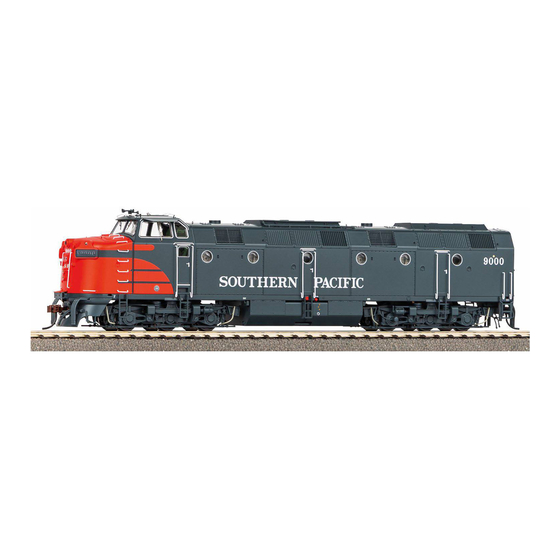
PIKO #97442 SmartDecoder XP 5.1 Sound
ML4000 Diesel Locomotive (North American
version) Reference Guide
Table of Contents:
Decoder overview
Sound decoder installation
Programming CVs
SUSI interface and the light control module / main PCB
Decoder overview:
The PIKO SmartDecoder XP 5.1 Sound inside the ML4000 is a powerful, NMRA DCC-Conformant, load-regulated, multiprotocol PluX22 sound decoder. It features high fidelity, 12
bit 8-channel sound with 2.5 watts of output that ensures distortion-free sound at all levels. The decoder can be used on DCC layouts as well as traditional DC analog layouts. It will
automatically detect what control mode is used on your layout. The decoder is RailCom® and RailCom Plus®-compatible for nearly instant registration on DCC systems with RailCom
technology.
It features an abundance of user-programmable sound and lighting functions along with multiple unit consisting and programmable motor speed curves. The two directional lighting outputs
and seven additional function outputs can be activated individually on keys F0 to F68. A slow-speed switching gear/mode, three starting and braking delays, and a plethora of locomotive
sounds can also be activated via any of the function keys. The decoder's sound module controls function outputs like fade-in / fade-out headlight effects. Sophisticated circuitry keeps the
decoder functioning in the event of short-term power loss like on dirty track. The Smart Decoder XP 5.1 Sound can be programmed with most DCC systems, but we strongly recommend
the PIKO SmartProgrammer device (PIKO item #56415) for advanced programming projects like Extended Function Mapping.
Decoder attributes:
•
NMRA DCC-Conformant
• Automatic detection of conventional DC operating mode
• Nearly silent operation thanks to auto-adaptive motor control
• 14, 28, and 128 speed steps
• Short (1-127) and long (128-9999) DCC addressing
• RailCom® and RailCom Plus®-compatible
• mfx® (Marklin DCC system) compatible
• DCC Programming on the Main (POM)
• Programmable via register, CV direct, or page programming
• Adjustable minimum, medium, and maximum speed levels
• Adjustable extended speed curve
• Switching gear/mode (1/2 normal locomotive speed).
• 3 adjustable acceleration and braking delays
• F0 - F12 can be programmed to operate while on analog layouts
• 7 special function outputs; direction-dependent and dimmable
• Directional light outputs; dimmable
• Marker lights can be switched on or off
• Four adjustable flashing patterns for outputs like Mars lights
• Adjustable headlight illumination time: light starts dim and then reaches full brightness
• Two adjustable light dimming settings for outputs A1 to A7
• Simple function mapping for lighting functions in F0 - F12 and A1 to A7
• Extended function mapping in F0 - F68 for switching multiple function outputs at the
same time (linked functions)
• Adjustable braking distances
• Recognizes automated DCC brake sections on your layout
• Speed-dependent activation / deactivation of function outputs
• Automatic shuttle train operation with adjustable halt times for automated train routing
Page
1
2
3
3
4
4
5
5-8
6-8
6-8
7-8
8
8-14
(computer-controlled train operation)
• Function icons can be displayed or hidden on DCC throttle's screen
• Suitable for 1.2 Amp DC and AC motors
• Overload protection for each function output
• Error memory for motor and function outputs
• Temperature overload protection
• Decoder programming lock
Decoder sound module:
• 12 bit resolution
• 8-channel sound
• 128 MBit sound storage for up to 495 seconds of digitized original sound
• 22.05 kHz audio sampling rate
• Powerful digital amplifier with 2.5 watt output
• Locomotive start-up / shutdown sequences
• Up to 32 switchable sounds accessed via function keys F0 to F68
• Load-dependent sound change (starting, uphill, downhill, braking, stationary, etc.)
• Adjustable volumes for overall sound and individual sounds
• Sound fader function
• Random sounds like cooling fans or air compressor; adjustable to speed thresholds
• Automatic brake squeal with adjustable speed threshold
• Automatic flange squeal with adjustable speed threshold
• Ability to upload locomotive sound files via the PIKO SmartProgrammer / SmartTester
• and much more!
Advertisement
Table of Contents

Related Manuals for PIKO 97442


Summary of Contents for PIKO 97442
-
Page 1: Table Of Contents
Decoder overview: The PIKO SmartDecoder XP 5.1 Sound inside the ML4000 is a powerful, NMRA DCC-Conformant, load-regulated, multiprotocol PluX22 sound decoder. It features high fidelity, 12 bit 8-channel sound with 2.5 watts of output that ensures distortion-free sound at all levels. The decoder can be used on DCC layouts as well as traditional DC analog layouts. It will automatically detect what control mode is used on your layout. - Page 2 Below are a couple of graphics showing what each pin on the decoder controls. If installing a decoder from another manufacturer, take note of which pin corresponds with which socket in the ML4000’s DCC interface! PluX22 Interface ML 4000 #97442 Name Pin Nr.
-
Page 3: First Time Use
The decoder is factory-set to DCC address 3, which you can now change if you desire. If you are using a RailCom Plus®-compatible digital control center (i.e. PIKO SmartControl) or an mfx®-compatible digital control center (Marklin), the decoder will log on automatically and can be used immediately. -
Page 4: Multiple Unit Operation; Consisting, Speed Matching
In addition to it’s DCC address, configuration CVs are the most important CVs in a decoder. These are CVs 12 and 29. A configuration CV normally contains settings which are represented in bits. On a programming screen like the PIKO SmartControl, bits are displayed underneath the CV that has been called up on the screen. The two tables below illustrate how a configuration... -
Page 5: Other Programming Options
Acceleration and Braking Delay (ABV) The PIKO XP 5.1 SmartDecoder can be programmed to use three different acceleration and braking delays (ABV - ABV1 - ABV2); each selected from a range of 0 - 255. To prevent jump starts, the decoder has a “soft start” feature that can be set in CV 53. Once the “soft start” takes place, the respective ABV delay kicks-in. The first ABV is set in CV 3 (start-up delay) and CV 4 (braking delay). -
Page 6: Function Mapping
Function key assignment for individual sounds can only be done with extended function mapping and cannot be programmed using individual CVs. Custom sound files To load a custom PIKO sound file onto the decoder, you will need the PIKO SmartProgrammer (# 56415) and (optional) the PIKO SmartTester (# 56416). Factory reset... -
Page 7: Extended Function Mapping
Simple and Extended Function Mapping The following decoder settings are possible with simple (CV 96 = 1) or extended (CV 96 = 6) function mapping. Keep in mind that the decoder is factory set to Extended function mapping (CV 96 = 6). Setting options for function output intensity (for DCC experts only!) The settings for each function output intensity are stored in a separate CV block in CVs 257 - 512. -
Page 8: Cv Tables
(Java Model Railroad Interface), the decoder profile for the ML4000 includes all CVs for the LightController. Any DCC system that can program CVs 1 – 1024 will also work. More information on the LightController is available along with a full CV chart. This is available to download on the PIKO America website on all ML4000 pages, www.piko-america.com... - Page 9 CV Table for the Smart Decoder XP 5.1 Sound Description Range Factory Setting* Short decoder address 1-127 Minimum speed (speed setting for when model starts moving at speed step 1) 0-255 Start-up delay 0-255 Braking delay 0-255 Maximum speed (must be greater than CV 2) 0-255 Medium speed (must be greater than CV 2 and less than CV 5) 0-255...
- Page 10 Description Range Factory Setting* Special function assignment 0-63 Bit 0=0 SUSI = Logic1 and Logic2 Bit 0=1 SUSI = SUSI Bit 1=0 When Bit 0 = 0, then SUSI = Logic1 and Logic2 Bit 1=1 When Bit 0 = 1, then SUSI = Servo1 and Servo2 Bit 2=1 A4 for digital coupler Bit 3=1 A5 for digital coupler Bit 4=1 Digital coupler outputs A4 and A5 are reversed...
- Page 11 Description Range Factory Setting* Alternative braking delay 2, (as a replacement for CV 4) 0-255 Function key number for ABV 1 (255=aus) 0-68 Function key number for ABV 2 (255=aus) 0-68 Deactivate function key number for ABV (255=off) 0-68 Function key number for switching (shunting) mode (255=off) 0-127 Chuff rate calibration per wheel revolutions (Sound) 0-255...
- Page 12 CV Table for programming function output effects (CV31 = 18, CV32 = 0, Bank 1024) Description Range Factory Setting* Output F0v Effect A 0 - 255 Output F0v PWM A 0 - 64 Output F0v Flags A 0 - 255 Output F0v Parameter 1 A 0 - 255 Output F0v Parameter 2 A...
- Page 13 Description Range Factory Setting* Output A6 Effect A 0 - 255 Output A6 PWM A 0 - 64 Output A6 Flags A 0 - 255 Output A6 Parameter 1 A 0 - 255 Output A6 Parameter 2 A 0 - 255 Output A6 Effect B 0 - 255 Output A6 PWM B...
- Page 14 4x reset F15 sequencer to 0; all lights on NOTE: This product is not a toy and is not meant for children under 14 years of age. PIKO is not liable for any damage caused by improper handling and/or failure to follow these instructions.
Need help?
Do you have a question about the 97442 and is the answer not in the manual?
Questions and answers