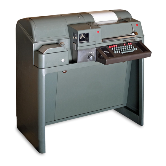
Teletype 28 Disassembly And Reassembly
Electidcal service units
Hide thumbs
Also See for 28:
- Technical manual (733 pages) ,
- Manual (228 pages) ,
- Adjustments (170 pages)
Advertisement
Quick Links
TELETYPE CORPORATION
Skokie, illinois,
U.S. A.
SECTION 573-133-702TC
Issue 2, June, 1966
28 ELECTIDCAL SERVICE UNITS
DISASSEMBLY AND REASSEMBLY
1.
GENERAL
1. 01
This section provides disassembly and
reassembly instructions for 28 electrical
service units used in teletypewriter sets.
It
is
reissued to provide additional
information in
a
standardized format. Since this is a general re-
vision, marginal arrows ordinarily used to indi-
cate changes and additions have been omitted.
1. 02
When it is necessary to remove the var-
ious
components
from the electrical
service unit, the appropriate wiring diagrams
should be
used
as
a reference.
1. 03
After the
disassembly procedure has been
followed,
reassembly procedure for most
components is obviously a reversal of the dis-
assembly procedure. Where necessary, reas-
sembly
information is given.
Note:
Remove
power from unit before starting
disassembly
procedure.
·
2.
DISASSEMBLY AND REASSEMBLY
2. 01
Removal
of 28
Electrical
Service Unit
from 28 Teletypewriter
Cabinet used with
28 KeyboardSend-Receive (28 KSR) or Receive-
Only
(28 RO) Teletypewriter.
(1) Raise dome of cabinet and disconnect all
plugs and
receptacles from the typing
unit.
(2)
Remove the typing
unit
in accordance with
the
section entitled
"28
Typing Unit, Dis-
assembly
and
Reassembly.
"
(3) Disconnect
all
plugs
and receptacles from
the
keyboard
and
remove
the keyboard.
( 4) Remove
the mounting
studs from each end
of
the
electrical service unit.
Note:
The electrical
service unit may now
be turned upside down
for servicing
or un-
wiring components.
(5) The various components may be removed
from the
unit by removing their mounting
screws on the top side of the unit and dis-
connecting cabling
and wires.
( 6)
·
If
it is desirable to remove the electrical
service unit completely from the cabinet,
disconnect the remaining wires and cables.
2. 02
Removal of Electrical Service Unit from
Skin- Tight KSR Sets (Located behind the
typing unit cover):
(1)
Unlatch electrical service unit cover at
each end and lift cover off.
(2) Remove the mounting studs from
each
end of the electrical service unit and lift
unit off base.
(3) Remove various components from
the
electrical service unit by removing
their
mounting screws and disconnecting wire or
cable connections as necessary.
2. 03
Removal of 28 Electrical Service Unit
from 28 Automatic Send-Receive Sets
(28 ASR):
(a) \Vithout auxiliary equipment
( 1) Raise the dome of the cabinet and dis-
connect all plugs and receptacles
from
the typing unit.
(2) Remove the typing unit in accordance
with the section entitled
"28
Typing
Unit, Disassembly and Reassembly.
"
(3)
Disconnect all plugs and receptacles
from the perforator- transmitter base.
(
4) Remove the mounting studs from
each
end of the electrical service
unit.
(5) Remove the power control switch
as-
sembly bracket at the right end of
the
unit and the line- test- key control assembly
at the left end.
( 6) Remove various components from
the
electrical service unit by removing
their mounting screws and disconnecting
wire or cable connections as necessary.
© 1966 by Teletype Corporation
All rights reserved.
Printed in U.S. A.
Page
1
Advertisement


Need help?
Do you have a question about the 28 and is the answer not in the manual?
Questions and answers