Teletype 28 Manual
Send-receive (ksr) and receive-only (ro) teletypewriter sets
Hide thumbs
Also See for 28:
- Technical manual (733 pages) ,
- Manual (228 pages) ,
- Adjustments (170 pages)
Table of Contents
Advertisement
Quick Links
Advertisement
Chapters
Table of Contents

Related Manuals for Teletype 28


Summary of Contents for Teletype 28
-
Page 7: Table Of Contents
TELETYPE CORPORATION SECTION 573-100-100TC Skokie, Illinois, U.S. A. Issue 1, February, 1964 28 KEYBOARD SEND-RECEIVE (KSR) AND RECEIVE-ONLY (RO) TELETYPEWRITER SETS DESCRIPTION page-width copy paper or continuous business PAGE CONTENTS forms. The sets translate the messages to a serial start-stop... - Page 10 S EC TION 573-100-100 KEYBO AR D Figure 3 Rack Mounted Send-Receive Teletypewriter Set TYPING UNIT Fig. feed and, in addition, switching facilities for remote controls, station selection, and other 3.03 The typing unit contains the mechanism applications. necessary for translating electrical in put signals into printed, alpha-numeric charac...
-
Page 11: Typing Unit
ISS 1, SECTION 573-100-100 TYPING UNIT C OPY HOLDER KEYBOARD ENCLOSURE D OOR PAPER SUPPLY) Figure 4 Wall Mounted Send-Receive (KSR) Teletypewriter Set Page 5... - Page 12 SECTION 573-100-100 CONTROL PANEL RO SET S ENCLOSURE K SR SET Figure 5 Typical Multiple KSR and RO Set Page6...
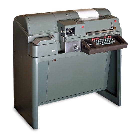
- Page 13 ISS 1, SECTION 573-100-100 MOTOR UNIT TYPING F.LECTRICAL UNIT SERVICE UNIT ENCLOSURE STORAGE AREA Figure 6 - Floor Model Keyboard Send-Receive (KSR) Teletypewriter Set Interior View Page7...
-
Page 14: Motor Units
SECTION 573-100-100 the set. Unlike the receive-only base, the send Vertical Tabulator - Advances a form to receive keyboard is equipped with mechanisms any predetermined position within the for generating and transmitting a teletypewriter form. signal. Form Feed-Out - Advances a form to MOTOR UNITS (Fig. -
Page 15: Technical Data
Per-Second 10.0 Unit Code 7.42 7.42 7.00 7.42 7.00 7.42 7.50 Bauds (Bits-per-second) 74.2 56.9 45.5 50.00 Frequency (Cycles/Second) 37.1 28.4 25.00 22.8 One Character Length Unit Pulse 13.5 17.6 20.0 20.0 20.0 22.0 22.0 Milliseconds Stop Pulse 19.1 24.9 30.0... -
Page 16: Printed Characters
SECTION 573-100-100 PRINTED CHARACTERS Type Pallet Arrangements - Standard, upper case arrangements include: Communications (Punctuation symbols) Fractions Weather symbols Individual pallets for upper and lower case characters are available separately for field installation. Type Styles and Spacing (Typical) Vertical Lines Per Inch Character Height Horizontal Characters Per Inch Style... - Page 17 ISS 1, SECTION 573-100-100 115 VAC CYCLES CONVENIENCE OUTLET MAINT OOFF COPY LIGHT SWITCH BELL BELl. FUNCTION BOX CONTACT LINE SHUNT RELAY MOTOR CONTROL RELAY TIME DELAY STOP MAGNET I� I � LINE RELAY LINE SHUNT RELAY CONTACT MOTOR CONTROL SIGNAL GENERATOR :��...
-
Page 18: Typing Unit Ribbon
S ECTION 573-100-100 TYPING UNIT RIBBON TYPING UNIT PAPER (FRICTION FEED) Type ..Standard yellow paper roll Style ....Black record ribbon Outside diameter .. - Page 19 SIGNAL REQUIREMENTS ..SIGNALING CODE ... . . GENERAL OUTLINE OF Figure 1 - 28 Typing Unit OPERATION ....DISTRIBUTION OF MOTION ..POSITIONING THE TYPE BOX ..
-
Page 20: General
GENERAL (Figs. 1 through 5 DESCRIPTION ....The basic function of the 28 typing unit 2.01 is to record in page printed form infor- VARIABLE FEATURES .. - Page 21 CODE BAR FRONT PLATE HORIZONTAL CARRIAGE MECHANISM MECHANISM TABULATOR Figure 2 - 28 Typing Unit Friction Feed Front View independently of the signal line from the local 2 .03 The speed of operation of the equipment keyboard or base mechanism.
-
Page 22: Main Shaft
PLATE FEED OUT KN OB PLATEN T YPE BOX VERT ICA L TABUL ATOR FORM OUT SPACING DRUM FRONT PLATE MECHANISM T YPE BOX CARRIAGE F igure 3 - 28 Typing Unit (S procket Feed) (Right Front View) Page 4... -
Page 24: Code Bar Mechanism
SECTION 573-115-100 CONNECTOR SHIFT FORK STRIPPER BLADE Figure 5 - Stunt Box Rear View to the next printing area on the paper, or spaces requirements for type box positioning, printing and stunt box operation. without printing, or on units so equipped, tabu lates horizontally, or returns the type box to PRINTING MECHANISM... -
Page 25: Spacing Mechanism
0 . 060 amperes STUNT BOX (Fig. 5) 3. 01 All electrical requirements for operation of the 28 typing unit are supplied through 2.13 The stunt box is a compact, self-contained associated equipment, such as a base, keyboard device with memory storage capabilities base or electrical service unit. -
Page 27: General Outline Of Operation
SECTION 573-115-100 magnets. The start pulse (spacing) of each code combination permits the start lever to fall to the rear behind the magnet armature and rotate to SIGNAL LINE LETTER t:':'ip the selector cam clutch. The range finder - CURRENT-+ mechanism permits adjustment of the angular relationship of the trip- off point to the optimum - NO CURREN... -
Page 28: Distribution Of Motion
573-115-100 SECTION clutch stop mechanism to engage the spacing and the type box clutch. The sequence in which tripped is, selector, cod e clutch, except when spacing is suppressed. these clutches are bar, function, type box, spacing and line feed. 4.09 The spacing clutch, when tripped by the However, the type box and spacing clutch en... -
Page 31: Three Stop Clutches
SECTION 573-115-100 SELECTOR CLUTCH STOP ARM BAIL CAM ---- --. NUMBER 5 SELECTOR LEVER CAM ---- --, NUMBER 4 SELECTOR LEVER CAM ----. NUMBER 3 SELECTOR LEVER CAM ----, SPACING LOCK LEVER CAM ---- --. MARKING LOCK LEVER CAM NUMBER 2 SELECTOR LEVER CAM NUMBER 1 SELECTOR LEVER CAM PUSH LEVER RESET BAIL CAM CODE BAR CLUTCH TRIP CAM... - Page 32 SECTION 573-115-100 is being received, the start (spacing pulse re SHOE SPRING leases the selector armature which, under the tension of its spring. moves away from magnet cores, thus unlatches start lever. The start lever rotates clockwise viewed from the right under tension of spring, moving the stop arm bail into the indent of the first cam.
- Page 33 573-115-100 SECTION INDEXING LOCK STUD RANGE SCALE RANGE FINDER SELECTOR MAGNET COILS KNOB RANGE FINDER SECTOR START LEVER CLUTCH DRUM MAIN SHAFT STOP ARM BAIL CLUTCH DISK CLU TCH SHOE LEV ER CAM DISK LUG STOP ARM Figure Selector Clutch 2nd Range Finder 6.04 The series of five selecting levers and the spacing lock lever swings toward the rear,...
- Page 34 SECTION 573-115-100 SELECTOR ARMATURE N0.4 TRANSFER LEVER PUSH LEVER MARKING RESET BAIL LOCK LEVER EXTENSIONS ON MARKING LEVER NO. 4 INTERMEDIATE SELECTING LEVER (RIGHT SIDE VIEW) PUSH LEVER Figure 14 - Selecting Mechanism and Transfer Mechanism selector cam clutch rotates, each selecting to the rear, below the armature, to lock it in the...
-
Page 35: Orientation
SECTION 573-115-100 the angular position at which the selector cam levers then return to their unselected (rear) clutch stops with respect to the selecting levers. position under their spring tension. When an optimum setting is obtained, the range finder knob is released. Its inner teeth engage ORIENTATION the teeth of the indexing lock stud to lock the... -
Page 36: Code Bar Mechanism
SECTION 573 - 1 15- 1 00 CODE SmFT BARS --- - - - - -� CODE (TOP VIEW) 1 2 C 3 SmFT LEVERS TRANSFER LEVERS Figure - Code Bar Shift Bar Positioning selecting mechanism push bars. The code bars CODE BAR OPERATION (Figs. - Page 37 573-115-100 SECTION POSITIONING THE TYPE tion of the clutch operates an eccentric and the shift lever drive shaft, shift lever drive arm and GENERAL shift lever drive link. The drive link moves two code bar shift levers in a scissors like action, 8.01 All of the characters (graphics) that may the front lever moving to the left, the rear lever...
-
Page 38: Letters-Figures Shift
573-115-100 SECTION RIGHT PRINTING PRINTING LEFT PRINTING CARRIAGE RIGHT CARRIAGE TRACK CARRIAGE TRACK PULLEY OSCILLATING RAIL PULLEY PULLEY LEFT OSCILLATING CARRIAGE RAIL PULLEY SPACING CUT-OUT DRAW LEVER WIRE PRINTING TRACK ROPE UPPER DRAW WIRE ROPE SPACING CUT-OUT ESCAPEMENT TRANSFER LEVER BAIL MARGIN DRAW WIRE ROPE... - Page 39 SECTION 573-115-100 The lower most code bar, designated S, 8.06 moved to the right (Fig. 20). This positions the contains a pin near its right end that left shift link vertically with its lower end over projects upward to permit engagement with the the left breaker slide bail.
-
Page 40: Vertical Positioning
SECTION 573-115-100 RIBBON SPOOL · BRACKET VERTICAL SUPPRESSION POSITIONING CODE BAR LOCK LEVER NO . CODE CODE MAIN SIDE LEVER COMMON FOLLOWER ARM CODE VERTICAL MAIN SIDE POSITIONING LEVER LEVERS MAIN ROCKER SHAFT MAIN SIDE LEVER DRIVE LINK (RIGHT SIDE VIEW) Figure Right Side Plate Mechanisms... -
Page 41: Horizontal Positioning
SECTION 573-115-100 FUNCTION CLUTCH TYPE BOX CLUTCH BOX CLUTCH TRIP ARM LATCH LEVER LATCH LEVER FUNCTION CLUTCH TRIP LEVER TRIP LEVER TYPE BOX CLUTCH CLUTCH TRIP LEVER SHAFT Figure Clutch Trip Mechanism The top row of pallets in the type box are then in each case, by the same bar that blocks the right side levers. - Page 43 ISS 1, SECTION 573-115-100 slide are pivoted, buckling- type drive links which will be located in the left half of the figures or extend downward to each end of the main bail. the letters field. In a similar manner, when the As the main bail moves downward under im...
- Page 44 573-115-100 SECTION PRINT HAMMER OPERATING OPERATING BAIL SPRING OPERATING BAIL BAIL ADJUSTING BRACKET SPRING LATCH CARRIAGE PRINTING TRACK OPE RATING BAI L LATCH SPRING PRINT HAMMER OPERATING BAIL ---- - PRINTING TRACK MAIN BAIL MAIN BAIL (LEF T F RONT VIEW) LINK MAIN BAIL DRIVE BRACKET...
-
Page 45: Printing
ISS 1, SECTION 573-115-100 The upper slide (operated from the number 4 POSITIONING (Figs. 23 and 25) code bar) is the second longest stop, and the lower slide (operated from the number 5 code The printing carriage rides on rollers 9.02 bar) is the third longest stop. -
Page 46: Spacing
ROCKER SHAFT SHAFT SPACING ECCEN TRICS ROCKER SHAFT CAM PLATE SPACING TRIP LEVER MAIN SHAFT SPACING SHAFT SPACING SHAFT HELICAL DRIVEN HELICAL DRIVING GEAR GEAR INTERMEDIATE BAIL (RIGHT FRONT VIEW) SPACING CLUTCH TRIP LEVER Figure 26 Spacing Mechanism Page 28... -
Page 47: Space Function
SECTION 573-115-100 which, in turn, is fastened to the spring drum is initiated when the code bars are set in a com and the spacing drum. The purpose of the spring bination equivalent to the spacing code combina drum, which contains a torsion spring, is to ten tion (all spacing except third pulse marking). -
Page 48: Ribbon Feeding
573-115-100 SECTION box carriage reaches the end of its travel, an each revolution of the type box clutch. They are actuator mounted on the face of the spring drum driven by ribbon drive links attached to the main 21). operates the switch contact. The angular posi... -
Page 49: Operation
(Fig. 28) and between the platen and three pres sure rollers. A paper pressure bail at the front RIBBON REVERSING of the platen equalizes pressure brought to bear on the paper by the pressure rollers. -
Page 50: Stunt Box Operation
SECTION 573-115-100 PAPER FINGER PAPER GUIDE PAPER STRAIGHTENER SHAFT PAPER RELEASE L EVER (RIGHT FRONT VIEW) Figure Friction Feed Platen Mechanism As in printing, the reception of function across the front of the platen hold copy paper 13.02 firmly against the plate, in position for print codes results in the positioning of the code bars The back edges of the code... - Page 51 573-115-100 SECTION SHIFT FORK POSITIONS SLOT MANDATORY WITH ASSOCIATED CODE NUMBER POSITION BAR INDICA TED LE TTERS-FIGURES UNSHIFT-ON-SPACE SHIFT CODE BAR F IGURES SHIFT LETTERS SHIFT StJPPRESSOR AUTOMATIC CR CODE BAR SUPPRESSOR CODE BAR ZERO CODE BAR ON-LINE SUPPRESSOR HORIZONTAL TAB CODE BAR FUNCTIONS NOT SUPPRESSO R...
- Page 52 SECTION 573-115-100 CODE BARS ROCKER SHAFT STRIPPER BLADE FUNCTION CLUTCH ASSEMBLY DRIVING LINK ECCENTRIC (LEFT REAR VIEW ) ASSEMBLY Figure Stunt Box (Function Linkage Unselected) the code bars are positioned for a function, each blade releases the function bars, any selected tine on the function bar for that function will be bar will move sufficiently forward (to the left, opposite a notch in the code bar.
-
Page 54: Carriage Return Function
SECTION 573-115-100 13.07 When the carriage return lever reaches the lowest point, carriage return latch bail locks it there. The disengagement of the spacing drum feed pawls from the spacing drum permits the spring drum to return the STRIPPER BLADE printing and type box carriages toward the left FUNCTION PAWL------,...------- -. - Page 56 SEC TION 573-115-100 SPACING DRUM SPACING DRUM FEED PAWLS SPACING DRUM FEED PAWL RELEASE LINK CARRIAGE RETURN DASHPOT LEVER PISTON SPACING SPACING DRUM STOP ARM SHAFT STOP ARM ROLLER TRANSFER SLIDE CARRIAGE RETURN CARRIAGE RETURN LATCH BAIL PLATE LATCH BAIL SPACING ECCENTRICS LEFT FRONT VIEW...
- Page 57 ISS 1, SECTION 573-115-100 � SINGLE- OUBLE IJNE FEE LEVER LINE FEED FUNCTION LEVER LINE FEED FUNCTION BAR OPERATING STRIPPER BLADE LINE FEED LINE FEED CLUTCH FUNCTION TRIP ARM PAWL STRIPPER LINE FEED CLUTCH CAM DISK LINE FEED CLUTCH TRIP LEVER MAIN SHAFT LINE FEED...
- Page 58 SECTION 573-115-100 PLATEN HAND WHEEL PLATEN HAND WHEEL SPUR GEAR PLATEN PLATEN SPUR IDLER GEAR SPUR GEAR LINE BARS LINE FEED RELEASE LEVER LINE FEED ECCENTRIC LINE FEED SPUR GEAR CLUTCH LINE FEED TRIP LEVER BELL CRANK LINE FEED ECCENTRICS LINE FEED CLUTCH AND LINE FEED...
-
Page 59: Letters-Figures Shift Function
ISS 1, SECTION 573-115-100 function. This mechanism, which always oper ates on the line feed function code bar arrange ELECTRICAL ment, is released only by the stunt box strip SWITCH per blade and, therefore, holds the spacing sup pression bail operated (forward) until the spac ing cycle is completed. -
Page 60: Sprocket Feed Typing Unit
SECTION 573-115-100 BRACKET ARM PAPER GUIDE CLAMP SCREW PAPER FINGER LATCH PAPER FINGER PAPER FINGER LATCH SPRING SPROCKE T (RIGHT FRO NT VIEW) RIGHT SIDE PLATE Figure 41 Sprocket Feed Platen Mechanism which are determined by external requirements. DESCRIPTIO N The contact arm configuration is changed as re... -
Page 61: Variable Features
SECTION 573-115-100 15.02 R eception of the input signal code com- gers are repositioned by depressing them manu bination representing horizontal tabula ally until the end of the paper guide shaft latches an indent on the release lever. tion operates the associated stunt box mecha nisms to move the function lever forward. -
Page 62: Vertical Tabulation And Form Out
573-115-100 SECTION 15.03 Tripping of the spacing clutch is initiated returns to its unoperated position. The latch in the same way as for normal printing bail releases the stop lever arm, and the clutch (10.01-10.02). As the trip lever moves down, stop lever blocks further rotation of the spacing however, it hooks over and pulls down the inter... - Page 63 ISS 1, SECTION 573-115-100 HORIZONTAL TABULATOR SLIDE ARM OPERATING LEVER CAM PLATE STRIPPER BAIL ARM LEVER BLOCKING CAM PLATE LEVER STRIPPER BAIL SPACING CLUTCH RESTORING CAM OPERATING LEVER EXTENSION LINK SPACING CLUTCH INTER MEDIATE ST O P LE VE R AR M SP AC ING BAIL TRIP LEVER...
-
Page 65: Automatic Carriage Return-Line Feed
ISS 1, SECTION 573-115-100 15.11 When the stop plate on the rotating disc function bars. When the automatic carriage re engages the pawl, the form out blocking turn-line feed code bar is positioned to the right, lever is moved upward, permitting the slides to however, the function bars and their associated pawls and levers operate. - Page 67 A. General D. Keyboard Lock Mechanism .. 2.01 E. Keyboard Unlock M':!chanism. The 28 keyboard is a device for convert- Margin Indicator Mechanism. ing the mechanical action resulting from the manual depression of a key into electrical pulses that are transmitted over a signal line.
- Page 68 RECE PTAC LE MARGIN INDICATOR MECHANISM FUNCTION KEYS KEYS FOR PRINTING Figure 1 -28 Teletypewriter Keyboard 2.03 Motive force for activating the keyboard The major sections of the keyboard are 2.05 is derived from the motor unit by way of the base assembly, keyboard mechanism, the typing unit.
- Page 69 ISS 1, SE CTION 57 3 -116-100 TYPING UNIT MOTOR UNIT WALL MOUNTED E NCLOSURE (COVER REMOVED) Figure 2 - 28 Teletypewriter Keyboard in Wall Mounted Set (Cover R emoved) P age3...
-
Page 70: Keyboard Mechanism
The belt in turn engages with and drives the belt keytop. pulley and the attached intermediate shaft as- SYNCHRONOUS PULSED CODE BAI \ C ONTACT MAGNET GUIDE S WINGER MECHANISM (·,, Figure 3 28 Teletypewriter Keyboard (Top View) Page 4... -
Page 72: Receive-Only Base
SEC TION 573-116-100 CODE LEVER UNrVERSAL BAIL EXTENSION UNIVERSAL BAIL LATCH LEVER CODE KEYLEVER Figure 5 - Code Bar and Code Lever Universal Bail Mechanis m Local transmitter control. RECEIVE-ONLY BASE (Fig. 2.14 The receive-only base is an aluminum, 2.15 The wall mounted receive-only base used sheet metal structure used in place of the in wall mounted RO sets diff e rs from the... - Page 73 ISS 1, SECTION 573-116-100 transfer levers remain in their normal left hand occurs when the key and corresponding code position (Fig. lever are about two-thirds of the way toward full stroke. The universal bail latch then moves �.02 locking wedge is mounted on the pro- downward under spring force developed by the jection of the lower position of all code universal bail latch spring.
-
Page 74: Positioning Of Code Bars
SECTION 573-116-100 SIGNAL GENERATOR SHAFT UNIVERSAL BAIL L ATCH LEVER CODE BAR Figure 7 - Code Bar Mechanism 3.07 The cams and their corresponding trans- fer to the appropriate section for description fer levers are numbered from rear to and principles of operation for the motor unit. front. -
Page 75: Resetting Of The Code Bars
ISS 1, SECTION 573-116-100 ing the right (or left) contacts and allowing a Resetting of the Code Bars (Fig. 7) marking (or spacing) pulse to be transmitted. 3.11 Reset of the code bars is accomplished 3.09 Similarly, the remaining transfer levers by means of an eccentric on the front of 2, 4, 5 and 6 are pulled downward by their the can1 assembly, which drives an eccentric... -
Page 76: Function Keys
SECTION 573-116-100 code bars have been moved to the left a sufficient CONTACT BOX distance to permit the code lever (that deter SPRING mined the permutation) to drop down out of the universal bail. This permits the universal bail SPACING CONTACT to rotate forward and move the non-repeat lever (SHOWN CLOSED) down and off the reset bail. -
Page 78: Local Line Feed Mechanism
SECTION 573-116-100 LINE FEED CLUTCH TRIP LEVER ....TYPING UNIT) LOCAL LINE FEED TRIP LINK SPRING LOCAL LINE FEED LEVER LOCAL LINE FEED BAIL___. .. F igure 12 Local Line Feed Mechanism Page... -
Page 79: Keyboard Lock Mechanism
573-116-100 SECTION KEYBOARD UNLOCK FUNCTION LEVER KEYBOARD LOCK BAR PAWL UNLOCK - KEYBOARD LOCK FUNCTION LEVER KEYBOARD UNLOCK FUNCTION LEVER Figure - Keyboard Lock Mechanism Figure - Keyboard Unlock Mechanism Keyboard Lock Mechanism (Fig. Margin Indicator Mecha.nism (Fig. 3.16 3.19 The keyboard may be locked manually The margin indicator cam disc on the (local) or electrically (remote). -
Page 80: Time Delay Mechanism
SECTION 573-116-100 MARGIN INDICATOR CONTACT MARGIN INDICATOR CAM DISC (ON LEVER SWITCH TYPING UNIT) Figure Margin Indicator Mechanism (local line feed) key is depressed. This opera 5.04 If a line signal is received before tion may be performed independent of the posi revolutions of the intermediate shaft, the tion of the main power switch. - Page 81 SECTION 573-116-100 ECCENTRIC "FOLLOWER PAWL INTERMEDIATE GEAR SHAFT MOTOR STOP /SWITCH SWITCH PLUNGER Figure 16 Time Delay Mechanism NON-REPEAT NON-REPEAT LEVER CRANK LEVER REPEAT KEY LEVER FUNCTION LEVER SPACE --- FUN CTION LEVER ON SPACE FEATURE CODE LEVER BAIL EXTENSION Figure 17 Repeat Mechanism Page 15,...
-
Page 82: Local Reverse Line Feed
It is installed on the keyboard only. Refer lever engages and lifts the lower end of the to the sectionalized literature for the 28 typing space repeat lever. As the space repeat lever unit for description of operation. moves clockwise viewed from the front , it en... -
Page 83: Answer-Back Mechanism
SECTION 573-116-100 ANSWER-BACK MECHANISM Figs. latch operating lever, the stop lever rotates counter-clockwise until it comes to rest against the mechanism base plate. Before coming to 5.13 The answer-back mechani.sm is an elec- tro-mechanical device which permits the rest the stop lever moves the blocking lever identity of a called station to be transmitted counter-clockwise, thereby unblocking the drive automatically to the originating station, in re... - Page 84 5 7 3-116-100 SECTION r-- -------------- SLOT SLOT U.C.D FIGURES VOLTS AC VOLTS AC CONTACTS CONTACTS (IN TYPING UNIT STUNT BOX) -- 1-- ------ ANSWER-BACK KEYBOARD CONTROL RELAY PULSING CONTACTS HERE-IS KEYBOARD �---- � CONTACT ...,. SPARK SUPPRESSOR r------- -, .
-
Page 85: Originating Station
ISS 1, SECTION 573-116-100 stop code blade having a letters combination, vented. At this point the operator must manu has an additional projection. When it is being ally unlock the keyboard to restore it to its rotated into the sensing position, the projection normal operating condition if the set is equipped contacts the stop lever, rotating it clockwise. -
Page 86: Synchronous Pulsed Transmission
SECTION 573-116-100 operation is such that the contact does not op SYNCHRONOUS PULSED TRANSMISSION erate until the selected function bar has first (Fig. 3 and 20} moved forward and then rearward). 5.27 Upon operation in the appropriate key- lever, the reset bail in the keyboard is 5.25 This arrangement converts a normally- moved to the right and releases the selected... - Page 87 Line (polar) relay assembly. Rectifier assembly. GENERAL Line test key assembly. 1.01 The 28 electrical service units serve as Capacitor-resistor assembly. an area of concentration for the wiring of 28-type apparatus and provide mounting facili Motor control assembly. ties for various electrical assemblies and com...
- Page 88 SECTION 573- 133-100 ELECTRICAL MOTOR CONTROL MECHANISM Figure 1 Typical 28 Electrical Service Unit Page 2...
-
Page 89: Line Shunt Relay
ISS 1, SECTION 573-133-100 PRINCIPLES OF OPERATION by a local de source, such as the rectifier as sembly (3.05). Operation of the relay is as fol LINE SHUNT RELAY {Figures 1 and 2) lows: 3.01 The signal line is connected throug:'l the 3. -
Page 90: Signal Line Limiting Resistance
SECTION 573-133-100 3.10 The relay motor control mechanism con- rectification, and a filter capacitor. Rectifier sists of a solenoid operator, a single assemblies are available providing outputs of pole, double-throw enclosed switch, a terminal 120, 300, and 500 rna., respectively. Each pro... -
Page 92: Selector Magnet Driver Assembly
SECTION 573-133-100 Open Line Position Stop Position 3.15 In this position, the signal line is open, 3.17 The electrical motor control mechanism the start magnets are de-energized, and will return to the stop position and stop the start magnet armature is released. With the the motor unit when a pulse is received from the control circuit (3.13). -
Page 93: General
1.01 components Send - Receive Incandescent lamps located under the dome il (KSR) and Receive-Only (RO) Teletype luminate the copy. A three-position switch writer Sets may be installed in the following controls the copy lamps. Accessible when the... - Page 94 SECTION 573-134-100 COPY DOOR RELEASE BUTTON COPY DOOR WINDOW COPY HOLDER RECEIVE -ONLY BASE Figure 1 - Floor Model Enclosure Page 2...
- Page 97 b'l�-134-100 ;:;.t!.t;'l'ION lli::S 1, A form-out alarm mechanism. unit enclosure are installed on a common base plate, with the cover occupying the forward A busy line indicator lamp. section. The close-fitting design of the cover provides a reduction in weight and noise, and A paper supply and accumulating shelf.
- Page 98 SECTION 573-134-100 2.11 All external signal and power connections the wall surface in areas where it is desired to are made through terminal boards in the conserve floor space. Mounting may be made electrical service unit. A receptacle is provided to a variety of wall materials, including: ma...
- Page 99 ISS 1, SECTION 573-134-100 ing area, and a window for viewing the printed winder assembly and wiring for installing and copy and for use as a copy paper tearing edge. connecting a typing unit and a motor unit. A copy lamp, controlled by the motor-power lower set of slides mount a send-receive key...
- Page 100 S ECTION 573-134-100 CONTROL PANELS CABLE ENTRY HOLES - OPEN LINE LAMPS POWER SWITCHES KEYBOARD SWITCHES LOC CR BUTTON LOC LF BUTTON � ACCESS DOOR Figure 6 Multiple KSR and RO Enclosure PageS...
- Page 101 ISS 1, SECTION 573-134-100 ( g ) Terminal blocks and terminal boards for allow the assembly to be pulled forward through connections between the electrical serv the access door and set on the floor for mainte ice assembly and wiring of the enclosure. nance purposes.
Need help?
Do you have a question about the 28 and is the answer not in the manual?
Questions and answers