Table of Contents
Advertisement
Quick Links
Advertisement
Table of Contents

Related Manuals for Comen K1


Summary of Contents for Comen K1
- Page 1 Patient Monitor BRIEF TRAINING shar e wi th the wor l d...
- Page 2 B r i e f I n t r o d u c t i o n S y s t e m O p e r at i o n D i s a s s e m b l y a n d H a r d wa r e I n t r o d u c t i o n Tr o u b l e s h o o t i n g M a i n t e n a n c e...
-
Page 3: Brief Introduction
Part 01 Brief Introduction • Product Introduction • Appearance • Accessory... - Page 4 I n t r o d u c t i o n Product full set K1 full set includes: • Main unit • Portable plug-in box • Expansion dock 110V-220V AC • DC power adaptor • Plug-in modules • Accessory...
- Page 5 • SpO2: COMEN, Masimo, Nellcor, Masimo Rainbow set • NIBP • IBP: 4 channel IBP • EtCO2: built-in, external module box; side stream, mainstream; COMEN, Masimo, Respironics • AG: Masimo side stream (with O2, without O2) • O2: Oxygen sensor, neonate WAKE UP •...
-
Page 6: External Power
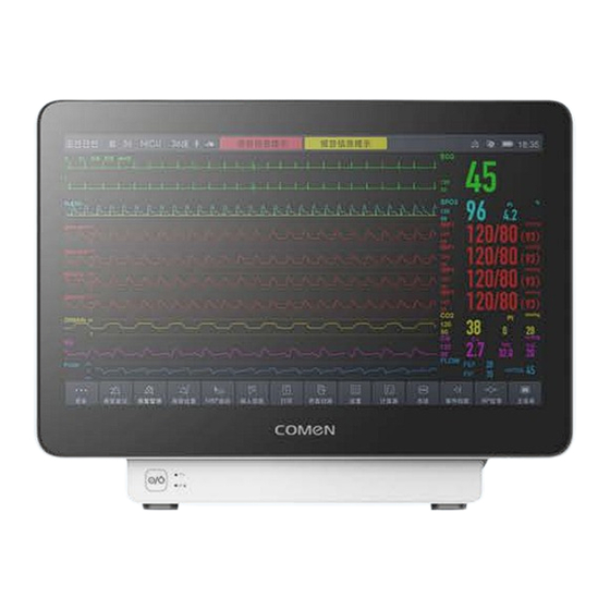
I n t r o d u c t i o n Power and environment External power • Expansion dock + main unit: 100-240V~; 50/60Hz; 1.0A-0.5A. • Power adapter: 15V DC; 2A. Rechargeable Li-ion battery • DC 10.8V 3350mAh, built-in battery. •... - Page 7 I n t r o d u c t i o n K1 Front View 1. Alarm indicator 2. Ambient light sensing 3. Display and touch screen 4. Power status indicator...
- Page 8 I n t r o d u c t i o n K1 Side View: parameter interfaces Power button EtCO2 (optional) speaker Parameter name Tip icons Parameter interface...
- Page 9 I n t r o d u c t i o n K1 Side View: power and data interface DC power socket: To connect with a power adaptor. Name plate: Manufacture data and SN number (important for reporting after-sale issues to COMEN)
- Page 10 I n t r o d u c t i o n K1 Rear and Bottom View Rear: Sliding rail for fixing K1 with other device Battery cover: Remove / replace the lithium battery from here...
-
Page 11: Multi-Function Connector
I n t r o d u c t i o n Accessory-Portable plug-in box The portable plug-in box has a handle for convenient transportation in hospital, and it is able to extend one parameter for K1 though the parameter plug-in box. This parameter can be: Rainbow SpO2 •... -
Page 12: Rear Interface
I n t r o d u c t i o n Accessory-Expansion dock The expansion dock can be combined with K1 directly or through the portable plug-in box. I has many ports on its rear to expand K1’s connection functions. - Page 13 I n t r o d u c t i o n Accessory-ECG (cable, electrode slices) 3 lead 5 lead 12 lead Electrode slices...
- Page 14 I n t r o d u c t i o n Accessory-SpO2 (extension cable, sensor) Masimo SpO2 COMEN SpO2 Nellcor SpO2...
- Page 15 I n t r o d u c t i o n Accessory-NIBP (tube, cuff) Neonatal: 3-6cm Adult: 4-8cm 46-66cm 6-11cm 33-47cm 7-13cm 20-28cm Child (Disposable)
- Page 16 I n t r o d u c t i o n Accessory-Temperature probe Intracavitary temperature probe Body surface temperature probe Adult, pediatric/neonatal Temp sensors are different size.
- Page 17 I n t r o d u c t i o n Accessory-IBP (cable, IBP transducer set) IBP cable IBP cable, and transducer set with Abbot interface. We also provide different interface IBP accessory of the following brands: • Utah •...
- Page 18 I n t r o d u c t i o n Accessory-Internal EtCO2 (Masimo, sampling tube) Masimo Nomoline sampling tube (with airway adaptor) K1 is also capable using an external EtCO2 module (side stream / mainstream). This function is realized through the portable plug-in box.
- Page 19 I n t r o d u c t i o n Accessory-External EtCO2 (Comen / Respironics / Masimo) Respironics Masimo Comen...
- Page 20 I n t r o d u c t i o n Accessory-AG, Masimo Multi-gas (sidestream) Multi-gas OR+ (with O2) Multi-gas AX+ (without O2)
- Page 21 I n t r o d u c t i o n Accessory-IBP IBP cable, and transducer set with Abbot interface. We also provide different interface IBP accessory of the following brands: • Utah • Edward • Braun • BD...
- Page 22 I n t r o d u c t i o n Accessory-C.O. (Cardiac Output) Infusion temperature Advised float catheter: C.O. interface cable sensor cable Edward 131F7...
- Page 23 I n t r o d u c t i o n Accessory-BIS (Bispectral Index) COVIDIEN BIS module BIS electrodes...
- Page 24 I n t r o d u c t i o n Accessory-Apnea wake-up function (for neonate) Oxygen sensor Apnea wake up probe...
- Page 25 I n t r o d u c t i o n Accessory-ICG (impedance cardiography, noninvasive cardiac output) ICG electrode slices ICG leads cable...
-
Page 26: System Operation
Part 02 System Operation • Basic settings • Patient and configuration management • Screen interface • Alarms • Parameters’ monitoring • Review, recording, print... - Page 27 S y s t e m O p e r a t i o n Basic settings – hotkeys From the main screen, operators can: • Enter [Patient Management] page • Enter [Alarm] page • Enter a parameter’s setup page by click its wave or value area •...
- Page 28 S y s t e m O p e r a t i o n Basic settings – main menu Page 2 Page 1 Touch and slide to switch the pages. Page 3...
- Page 29 S y s t e m O p e r a t i o n Patient management 1. Edit the patient information 2. Discharge a patient when the monitor is ready to be used on a new patient. 3. Search, delete discharged patients in [discharged patients].
- Page 30 S y s t e m O p e r a t i o n Display 1. Choose a screen mode 2. Set the title layout of the normal screen 3. Set large fonts screen 4. Set the brightness 5. Turn on / off the display of a parameter 6.
- Page 31 S y s t e m O p e r a t i o n Alarm Setup 1. Turn on / off the alarm for each parameter 2. Set the High / Low limits for each alarm 3. Set the priority for each alarm 4.
- Page 32 S y s t e m O p e r a t i o n Review Review: • Tabular / Graphic Trends • Events • Full Disclosure Set the tabular / graphic options to optimize the display of these data: •...
- Page 33 S y s t e m O p e r a t i o n Configuration management 1. Select the monitor department 2. Select a default patient 3. Select the default config once monitor is started 4. Save / delete a user-defined configuration 5.
- Page 34 S y s t e m O p e r a t i o n System and Maintenance 1. Set the volumes of QRS, key click, alarm, reminder 2. Set the system time 3. Check the system version 4. Enter Demonstration mode 5.
-
Page 35: Software Update
S y s t e m O p e r a t i o n Software Update 8Gb Sandisk Around 5 minutes 1. Put this File "SOFTUPDATE" into root directory of USB flash disk. 2. Insert and Startup the machine. 3. - Page 36 Part 3 Disassembly and hardware Introduction • Lithium battery • Screen housing assembly • Parameter module • SpO2 module • Mainboard • Connector board • Side panel assembly • Internal EtCO2 module • NIBP valves and pump...
- Page 37 H a r d w a r e I n t r o d u c t i o n Hardware structure diagram...
- Page 38 H a r d w a r e I n t r o d u c t i o n The tools to disassemble K1 1. 6mm screwdriver, for 3.0 screw. 2. 4mm screwdriver, for 2.0 screw. 3. Tweezers.
- Page 39 1. Remove the 2 screws on battery cover • The internal battery is 3350mAh, 10.8V. It can 2. Unplug the battery cable support K1 to keep running independently for 3. Remove the battery at least 10 hours. • It takes 3 to 5 hours to charge the battery to...
- Page 40 H a r d w a r e I n t r o d u c t i o n Screen housing assembly 1. Remove the 2 screws near the serial port on housing. 2. With a tweezers, unplug the screen socket from mainboard carefully.
- Page 41 H a r d w a r e I n t r o d u c t i o n Parameter module Sockets for Sockets NIBP vales connecting and pump connector board SpO2 module 1. Remove the 3 screws on the parameter module. 2.
- Page 42 H a r d w a r e I n t r o d u c t i o n SpO2 module COMEN SpO2 Masimo SpO2 Nellcor SpO2 SpO2 board realizes SpO2 signal acquisition, amplification simulation, relative digital-to-analog conversion and signal processing.
- Page 43 H a r d w a r e I n t r o d u c t i o n Mainboard Alarm light 1. Remove the 4 screws on the mainboard. 2. Unplug the pins from the connector board. 3. Unplug the switch button cable. Power / battery status light 4.
- Page 44 H a r d w a r e I n t r o d u c t i o n Connector board 1. Remove the 3 screws fixing connector board. 2. Remove the connector board. Connector board is to communicate with parameter module, mainboard, and to connect serial port socket(connecting Kpro monitors), DC power socket.
- Page 45 H a r d w a r e I n t r o d u c t i o n Side panel assembly 1. Remove the 3 screws fixing the side panel assembly. 2. Unplug the NIBP tube, remove the side panel assembly. Side panel assembly is the interface to connect with accessories and patient.
- Page 46 H a r d w a r e I n t r o d u c t i o n Internal EtCO2 module Main bracket CO2 module Waste tube 1. Remove the screws on the main bracket. interface 2. Unplug the waste tube of side panel. adaptor 3.
- Page 47 H a r d w a r e I n t r o d u c t i o n NIBP valves and pump 1. Remove the 2 screws(PB2.0x6mm) of 1. Remove the 3 screws on the main bracket. valves bracket. 2.
- Page 48 H a r d w a r e I n t r o d u c t i o n K1 exploded view...
- Page 49 H a r d w a r e I n t r o d u c t i o n K1 exploded view Material name Material name Material name main housing IBP connector Base button connecting rod backplane NIBP connector...
- Page 50 Part 4 Troubleshooting...
-
Page 51: Display Fault
T r o u b l e s h o o t i n g Display fault Fault Phenomenon Possible Reason Inspection and Repair Check whether the screen-related connections are good, and Bad internal connection reconnect the ones that are not plugged in, loose, or poorly connected Mainboard hardware failure Replace the mainboard... -
Page 52: Power Fault
T r o u b l e s h o o t i n g Power fault Fault Phenomenon Possible Reason Inspection and Repair Battery is empty Charge, replace the built-in lithium battery Power cord is loose or damaged Replace the power cord Screen is dark, abnormal or the machine turns on/off automatically Power adapter failure... - Page 53 T r o u b l e s h o o t i n g Speaker and alarm light fault Fault Phenomenon Possible Reason Inspection and Repair Loudspeaker connection loose and disconnection Check speaker connections Abnormal speaker sound, or no sound Horn failure replace the horn Mainboard failure...
- Page 54 T r o u b l e s h o o t i n g ECG fault Fault Phenomenon Possible Reason Inspection and Repair Check the various settings of the ECG to confirm that the Incorrect lead type setting settings are correct Poor contact between electrode pads and human body Replace pads, or clean skin, use couplant No ECG waveform can be detected, no heart rate value, and sometimes there...
- Page 55 T r o u b l e s h o o t i n g Resp fault Fault Phenomenon Possible Reason Inspection and Repair Weak patient signal Try increasing the Resp gain Abnormal respiration waveform or no Check and replace accessories to make sure they are not waveform, undetectable respiration Poor contact of electrode pads and damaged lead wires damaged and connected properly...
- Page 56 T r o u b l e s h o o t i n g Temp fault Fault Phenomenon Possible Reason Inspection and Repair Improper placement of the temperature probe Correctly place the temperature probe Inaccurate temperature measurement, Temperature probe malfunction Replacing the Temp accessory or other abnormalities Parameter module failure...
- Page 57 T r o u b l e s h o o t i n g SpO2 fault Fault Phenomenon Possible Reason Inspection and Repair The SpO2 probe is not placed in the wrong position, and Check that the SpO2 measurement is operating correctly the patient's condition is not good The SpO2 cannot be measured, the SpO2 probe is not clean enough...
- Page 58 T r o u b l e s h o o t i n g NIBP fault Fault Phenomenon Possible Reason Inspection and Repair Inappropriate NIBP settings Check settings: pre-inflation value, patient type Incorrect NIBP operation Choose the right cuff, and ensure patient stability It can be inflated, but the NIBP value cannot be measured.
- Page 59 T r o u b l e s h o o t i n g IBP fault Fault Phenomenon Possible Reason Inspection and Repair Zero calibration is required after powering on or IBP zeroing not performed replacing the IBP sensor IBP waveform and value are not IBP sensor or IBP cable fault Replace accessories...
- Page 60 T r o u b l e s h o o t i n g EtCO2 fault Fault Phenomenon Possible Reason Inspection and Repair No CO2 zeroing before use Perform zero calibration of the EtCO2 probe Incorrect settings such as altitude Check EtCO2 settings to ensure proper settings Inaccurate measurement of EtCO2 Replace accessories such as sampling tube, drying tube,...
- Page 61 T r o u b l e s h o o t i n g Solution • change some settings correct • We will provide guide. • correct some wrong operations • reconnect cable or part inside • Please refer to Service Manual or User Manual for quick solution.
- Page 62 T r o u b l e s h o o t i n g Warranty policy COMEN provides 24 months warranty for the devices (main unit) and 6 months warranty for the accessories, free of charge. The warranty period begins from the date products are shipped to customer.
- Page 63 T r o u b l e s h o o t i n g After-sale issue procedure...
- Page 64 T r o u b l e s h o o t i n g Service / repairing requirements For you to give fastest possible response to the end users, we recommend: • You buy and keep a learning device in your warehouse. So you technicians can learn the operation and repairing.
-
Page 65: Maintenance
Part 05 • Battery Maintenance • Cleaning and disinfection • Maintenance schedule... - Page 66 M a i n t e n a n c e Battery The built-in battery must be charged after each use to ensure sufficient battery reserve. Check battery performance The battery life varies with the storage and using habit. The battery performance will degrade gradually if the battery is not being used for a long time.
- Page 67 M a i n t e n a n c e Battery Optimize battery performance If it is the first time to use the battery, please ensure that the battery has undergone at least two complete optimization cycles. A complete optimization period means uninterrupted charging till the battery is fully charged, and then discharging it till the monitor shuts down automatically.
- Page 68 M a i n t e n a n c e Cleaning and disinfection Before transporting the monitor, or when you clean the device, please observe the following precautions: • Please dilute detergent and disinfectant as specified in the user manual, or use a concentration as low as possible.
- Page 69 M a i n t e n a n c e Maintenance schedule Before use, or every 6-12 months, check: • Operating environment, power supply is appropriate. • Device and accessory are in good condition. • The power cord is in good condition. •...
- Page 70 M a i n t e n a n c e Maintenance schedule Per day 3 months 2 years Check: • Safety check Clean the surface • ECG check Device works well • NIBP leakage test, NIBP verification Accessory works well •...
- Page 71 T h a n k s THANKS YOU FOR WATCHING Copyright © 2020 Shenzhen Comen Medical Instruments Co., Ltd. All rights reserved.
Need help?
Do you have a question about the K1 and is the answer not in the manual?
Questions and answers