
Subscribe to Our Youtube Channel
Related Manuals for Comen CM300


Summary of Contents for Comen CM300
- Page 1 Three-Channel Electrocardiograph CM300 User Manual Shenzhen Comen Medical Instrument Co., Ltd.
- Page 2 Copyright Version: A Date: 2012 /10 Part No: 046-000080-00 Statements Our company makes no warranty of any kind with regard to this material, including, but not limited to the implied warranties of merchantability and fitness for a particular purpose. Our company assumes no responsibility for any errors that may appear in this document, or for incidental or consequential damage in connection with the furnishing, performance or use of this material.
- Page 3 Note: A NOTE provides useful information about a function or procedure.
-
Page 4: Table Of Contents
Contents Chapter 1 Safety Guidance ..........................1 1.1 Safety Information ......................1 1.2 Warnings and Cautions ....................1 1.2.1 Safety Warnings ....................1 1.2.2 Battery Care Warnings ..................3 1.2.3 General Cautions ....................4 1.2.4 Cleaning & Disinfection Cautions ................ 5 ... - Page 5 5.7ECG Record ........................33 5.8 Switch Off ........................34 Chapter 6 Prompt Information ........................35 Chapter 7 Clean, Care and Maintenance ....................36 7.1 Clean..........................36 7.1.1 Clean the Main Unit and Patient Cable ............... 36 7.1.2 Clean the Electrodes ....................
-
Page 6: Chapter 1 Safety Guidance
Chapter 1 Safety Guidance 1.1 Safety Information The design of the 3-channel electrocardiograph complies with international standard IEC 60601-1 Medical Electrical Equipment: General Requirements for Safety and IEC 60601-2-25 Particular Requirements for the Safety of Electrocardiographs etc. The classification of this equipment is Class І, type CF, which means a higher degree of protection against electric shock and the patient connection is fully isolated and defibrillation protected. - Page 7 ♦ The electrocardiograph is provided for the use of qualified physicians or personnel professionally trained. And they should be familiar with the contents of this user manual before operation. ♦ Only qualified service engineers can install this equipment. And only service engineers authorized by our company can open the shell.
-
Page 8: Battery Care Warnings
♦ In order to avoid burning, please keep the electrode far away from the radio knife while using electrosurgical equipment simultaneously. WARNING ♦ Accessory equipment connected to the analog and digital interfaces must be certified according to the respective IEC standards (e.g. IEC 60950 for data processing equipment and IEC 60601-1 for medical equipment). -
Page 9: General Cautions
♦ When the battery’s useful life is over, contact with the manufacturer or local distributor for disposal or dispose the battery according to local regulations. 1.2.3 General Cautions CAUTION ♦ Avoid liquid splash and excessive temperature. The temperature must be kept between and 40 while working. -
Page 10: Cleaning & Disinfection Cautions
The data should be recorded in an equipment log. If the device is not functioning properly or fails any of the above tests, the device has to be repaired. ♦ Ruptured fused must only be replaced with the same type and rating as the original. ♦... -
Page 11: Function Features
2.1 Function Features ♦ Low weight and compact size ♦ Touch key for easy operation ♦ High resolution thermal printer, recoding frequency response ≤150Hz ♦ 12-lead gathered and amplified simultaneously, 3-channel built-in printer. ♦ Automatic mode and manual mode optional ♦... - Page 12 Mains supply Battery indicator Battery recharging indicator...
-
Page 13: Chapter 3 General Information
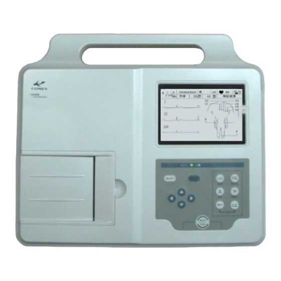
Recorder Control Panel RS232 Interface Patient Cable Socket External Input /Output socket Figure 3-1 Main Unit USB socket Product Information: 1) Logo 2) Model CM300 3) Brand Name Three-channel Electrocardiograph 4) Classification Symbol Equipment of CF type with defibrillator proof... -
Page 14: Lcd Screen
3.1.1 LCD Screen The LCD Screen specification: 320×240 dot single color LCD Screen Figure 3-2 CM300 Main Interface Name Explanation Show the falling off state of the lead, white color Lead State Diagram shows that the lead is connected and black point shows the falling off state of the lead. -
Page 15: Control Panel And Keys
Display and current time and battery capacity Time / Battery Display prompt information (“demonstration, lead Prompt Information off, printing, analyzing, sampling” and so on.) Waveform Area Current Waveform Display Diagram Area Lead State Diagram 3.1.2 Control Panel and Keys Indicator Lamp Mains supply indicator lamp: when mains supply is used, the lamp will be light. - Page 16 Press this key to review the patient records that saved in the record window. 4) 1mV Calibration Key Under manual mode, this key can be pressed to record a 1mV calibration pulse at any time while recording. Under auto mode, this key can be pressed to review the electrocardiogram that recorded last time.
-
Page 17: Patient Cable Socket And Signal Interface
7) PRINT/STOP Key Used to begin recording and stop recording. 8) ON/OFF Key When the unit has been powered on, press this key to turn on it. Press again to turn off it. 9) MENU Key Press this key to enter menu settings. 3.2 Patient Cable Socket and Signal Interface There are sockets including the patient cable socket, RS232 socket, external input/output socket and USB interface (reserved) at the right side of the main unit as Figure 3-1 shows. -
Page 18: Mains Connection And Switch
2) RS232 Socket WARNING RS232 interface is 1500V AC isolated intensity and the maximum voltage applied should not exceed +15V DC. Definition of corresponding pins: Signal Signal Signal RxD (input) TxD (output) 3.3 Mains Connection and Switch Potential Equalization Terminal Mains Supply Socket 1) Potential Equalization Terminal Potential equalization conductor provides a connection between the unit and the... - Page 19 Battery Compartment Fuse Label 1) Battery Compartment The battery label indicates the rated voltage and rated capacity of rechargeable Lithium battery pack. Rated voltage: 14.8V, Rated capacity: 2000mAh. Attention – general warning (see accompanying document) WARNING Improper operation may cause the battery to be hot, ignited or exploded, and it may lead to the decrease of battery’s capacity.
- Page 20 compartment and replace the battery. And the battery of same model and specification provided by manufacturer must be used. 2) Mains Supply Shift Switch Mains supply with rated input voltage 230V (220V~240V) or 115V (100V~115V) can be chosen by the shift switch according to local mains supply specification. : Only qualified installation or service engineer can shift the mains shift WARNING switch according to local mains supply.
-
Page 21: Chapter 4 Operation Preparations
Chapter 4 Operation Preparations CAUTION Before use, the equipment, patient cable and electrodes should be checked. Replace it if there is any evident defectiveness or aging which may impair the safety or performance. And be sure that the equipment is in proper working condition. 4.1 Power and Earthing WARNING If the integrity of external protective conductor in installation or arrangement is in... -
Page 22: Loading/Replacing Record Paper
: Potential equalization conductor of the unit should be connected to the WARNING potential equalization bus bar of the electrical installation when necessary. 4.2 Loading/Replacing Record Paper There are two kinds of paper can be used as ECG record paper. One is Rolled thermosensitive paper with 80mm width, and the other is folded thermosensitive paper with 80mm width. -
Page 23: Patient Cable Connection
Paper Tray Recorder Casing Thermal Print Head Printer Platen Loading/Replacing Process for Folded thermosensitive paper: 1) Place fingers under the flange of the recorder casing, pull upwards directly to release the casing; 2) Remove remain paper in the Paper Tray if necessary; 3) Take off the wrapper of folded thermosensitive paper, and then put it in the Paper Tray with the paper’s grid side facing upward and the thermal print head;... -
Page 24: Electrodes Connections
Connect Main Cable: Plug the connector of main cable into the patient cable socket on the right side of the unit according to the direction of arrow on the plug, and then secure it with two screws. 4.4 Electrodes Connections Chest Electrode: Suction Bulb Electrode... - Page 25 Chest 5 White/black Brown/orange Chest 6 White/violet Brown/violet As the following figure shows, the chest electrodes’ position on body surface is C1: Fourth intercostals space at right border of sternum C2: Fourth intercostals space at left border of sternum C3: Fifth rib between C2 and C4 C4: Fifth intercostals space on left midclavicular line C5: Left anterior axillary line at the horizontal level of C4 C6: Left midaxillary line at the horizontal level of C4...
-
Page 26: Inspection Before Power On
Clean electrode area on chest surface with alcohol; Daub the round area of 25mm diameter on each electrode site with gel evenly; Place a small mount of gel on the brim of chest electrode’s metal cup; Place the electrode on chest electrode site and squeeze the suction bulb. Unclench it and then the electrode is adsorbed on chest. -
Page 27: Chapter 5 Operation Instructions
Switch off these devices when necessary. ♦ Keep the examination room warm to avoid muscle action voltages in ECG signal caused by cold. 2) Power Supply: ♦ If mains power used, please check whether the power cord has been connected to the unit well. -
Page 28: Automatic Mode
♦ While using built-in rechargeable lithium battery, press ON/OFF key on the control panel directly to turn on the unit, and then the battery indicator ( ) is lit. After self-test, the machine is ready for examination and recording. 5.2 Automatic Mode Automatic recording mode is provided by the machine. -
Page 29: Ecg Recall
5) 1mV calibration key can be pressed to print out 1mV pulse wave in the record while ECG recording; 6) Press PRINT/STOP key to stop printing after finishing ECG record. LEAD left and right arrow key can be pressed to switch the lead during the course of recording. -
Page 30: Moving In The Sub-Menus
320×240 dot single color LCD Screen 5.5.2 Moving in the sub-menus Press UP or DOWN key to choose the setting items; arrow key arrow 5.5.3 Parameter modification Press LEFT arrow or RIGHT arrow key to modify a parameter; 5.6 Settings 5.6.1Register Settings Press Menu key to select “Setting”... - Page 31 Press the arrow keys group to select the five options settings of “Register, Lead Options, Filter Options, Print Options and System Options”. Press the arrow keys group to set a submenu. (1) Input the Characters Input the patient information on the “Register” setting interface: Character Input Interface Inputting Method: Press MENU key to Patient Information Setting item...
-
Page 32: 2General Settings
(8) HOSPITAL: Hospital Name (Letters: not more than 20 characters; English: not more than 10 letters) (9) DOCTOR : Doctor’s Name (Letters: not more than 20 characters; : not more than 10 letters) 5.6.2General Settings Press the “MENU” key to enter the “Setting” menu, select the “General” as shown in the following figure: General Interface Filter setting menu includes 4 filter settings: AC filter, EMG filter, drift filter and lowpass filter. -
Page 33: 3Print Settings
Lead Order Lead Group 1 Lead Group 2 Lead Group 3 Lead Group 4 Standard І, II, III aVR, aVL, aVF V1, V2, V3 V4, V5, V6 Cabrera aVL, І, -aVR II, aVF, Ш V1, V2, V3 V4, V5, V6 (7) SAMPLE MODE: Real time and Pre-sampling When the sampling mode is set as real-time sampling, the user press the “START/STOP”... - Page 34 Figure 5-6 Print Interface (1) RECORD LENGTH : 3S,6S,10S. (2) RECORD SPEED: the paper driving speed of the recorder, there are five options for the user to set such as 5mm/sec, 10mm/sec, 12.5mm/sec, 25mm/sec and 50mm/sec. Note: For the rhythm mode and automatic mode, the print only supports the paper driving speed of 25mm/s and 50mm/s.
-
Page 35: System Settings
When it is set as 6×2+1R, 12 leads of average template waveforms are recorded in 6 channels and 2 sequences and add 1 average template waveform of the rhythm lead. When it is set as “Off”, there is no average template output. (6) SAVE OPTIONS: Save only, Print&Save, off When the storage option is set as “Save only”, the ECG data recorded under the automatic working mode will be stored in the document management “File”... - Page 36 System Interface LANGUAGE: The user can set the language set on the display screen in the electrocardiograph and the language used in the ECG records. English and English are provided to select. DEMO MODE: On, Off. WARNING Waveform demonstration is the simulated demonstrate waveform set by the manufacturer to show the equipment performance and help the user to conduct training.
- Page 37 Setting System Default Value Channel Mode 3×4+1R Lead Mode Standard Sampling Mode Real-time Sampling Close Lead State Diagram Sampling Order Synchronous Sampling of Each Group Rhythm Lead AC Filter 50HZ EMG Filter Close Drift Filter 0.15Hz 100Hz Lowpass Filter Printing Speed 25mm/s Patient Information Detailed...
-
Page 38: Ecg Record
5.7ECG Record As the above figure shows, the ECG record includes: sensitivity, filter settings, date and time, 1mV calibration pulse, lead name, ECG, paper speed, heart rate, model of the equipment and version number. The user can recall the ECG waveform to observe. If the ECG data before the recall is less than 10s, the user need to wait until the electrocardiograph has gathered data for 10s to freeze the operation. -
Page 39: Switch Off
5.8 Switch Off When built-in battery pack used, press ON/OFF key directly to turn off the unit after finishing ECG record. When mains supply used, press ON/OFF key first after finishing ECG record and then switch off the mains supply by pressing the switch on the left side of the unit. Pull off the plug from the outlet last. -
Page 40: Chapter 6 Prompt Information
Chapter 6 Prompt Information Prompt information will be displayed on the bottom right corner of LCD screen when there is something wrong. Prompt information provided by the machine and corresponding cause is listed in Table 6-1. Table 6-1 Prompt Information and Causes Prompt Causes Information... -
Page 41: Chapter 7 Clean, Care And Maintenance
Chapter 7 Clean, Care and Maintenance 7.1 Clean CAUTION Turn off the power before cleaning and disinfection. Mains supply must be switch off if it has been in use. 7.1.1 Clean the Main Unit and Patient Cable The surface of the main unit and patient cable can be wiped with a clean soft cloth damped in soapy water or non-caustic neutral detergent. -
Page 42: Disinfection
7.2 Disinfection To avoid permanent damage to the equipment, disinfection can be performed only when it has been considered as necessary according to your hospital’s regulations. Before disinfection clean the equipment first. Then wipe the surface of the unit and patient cable with hospital standard disinfectant. -
Page 43: Record Paper
automatically. And then the battery recharge indicator lamp ( ) and the mains supply indicator lamp ( ) will be lit at the same time. During the course of recharging, the symbol “ will flash in the top right corner of LCD screen. When the capacity of battery is full, ”... -
Page 44: Maintenance Of Main Unit, Patient Cable & Electrodes
each other. 7.4.3 Maintenance of Main Unit, Patient Cable & Electrodes The following safety checks should be performed at least every 24 months by a qualified person who has adequate training, knowledge, and practical experience to perform these tests. a) Inspect the equipment and accessories for mechanical and functional damage. b) Inspect the safety relevant labels for legibility. - Page 45 ♦ Align the patient cable to avoid twisting, knotting or crooking in closed angle while using. ♦ Store the lead wires in bigger wheel to prevent any people from stumbling. ♦ Once damage or aging of the cable patient has been found, replace it with a new one immediately.
-
Page 46: Chapter 8 Service Warranty
Chapter 8 Service Warranty Material and Manufacture The warranty period for the main unit and the accessories is 12 months from the date of shipment. Our company warrants that there’s no defect in material and manufacture. During the warranty period, our company will repair or replace the defective part free if the defect has been confirmed as material or manufacture defect. -
Page 47: Appendix I Accessories And Ordering Information
Appendix I Accessories and Ordering Information : Only patient cable and other accessories supplied by our company can be WARNING used. Or else, the performance and electric shock protection can not be guaranteed. Table 9-1 Accessories List Accessory Quantity Power cord 1 pc Patient Cable 1 unit... -
Page 48: Appendix Ii Technical Specifications
Appendix II Technical Specifications MDD93/42/EEC, IEC60601-1, EN 60601-1-4, IEC60601-2-25, Safety Standards EN 60601-2-51, EN ISO14971, EN 55011, ANSI/AAMI EC-11 Anti-electric-shock type: Class І with internal power supply Classification Anti-electric-shock degree: Type CF Degree protection against Ordinary equipment (Sealed harmful ingress of water: equipment without liquid proof) Disinfection/sterilization method: Refer to the user manual for details... - Page 49 Folded thermosensitive paper Record Paper: Rolled thermosensitive paper Width of the Record 80mm Paper Effective Record 72mm Width 5 mm/s,10mm/s,12.5 mm/s, 25mm/s, 50mm/s Paper Speed: (±2%) ECG Unit Leads: 12 standard leads Acquisition Mode: simultaneously 12 leads A/D Resolution: 12 bits Time Constant: ≥5s Frequency Response:...
- Page 50 Shenzhen Comen Medical Instrument Co., Ltd. www.szcomen.com Floor 7, Block 5, 4th Industrial Area of Nanyou, Nanshan District, Shenzhen, China Tel: +86-755-26408879 Fax: +86-755-26401232 - 45 -...
Need help?
Do you have a question about the CM300 and is the answer not in the manual?
Questions and answers
The Comen CM300 3channel ECG Machine has no display when turn on but the alarm sound is on.
The issue could be related to a malfunction in the main board, display processing, or power supply components. Since the alarm sound is on, the CPU system is likely functioning, but the LCD panel may not be receiving power or data. Possible causes include:
1. Faulty LCD Panel – The display module may be damaged or disconnected.
2. Power Supply Issue – The inverter or power connection to the LCD could be faulty.
3. Main Board Malfunction – The CPU system may not be sending display signals properly.
4. Loose or Damaged Connections – Cables between the main board and LCD panel may be loose or broken.
Checking power connections, reseating cables, and testing the LCD panel can help identify the exact cause.
This answer is automatically generated