Table of Contents
Advertisement
Quick Links
Advertisement
Table of Contents

Related Manuals for Vermont Castings KHLDV Series


Summary of Contents for Vermont Castings KHLDV Series
- Page 1 This Owner's Manual is provided and hosted by Appliance Factory Parts. MAJESTIC KHLDV400NV Owner's Manual Shop genuine replacement parts for MAJESTIC KHLDV400NV Find Your MAJESTIC Fireplace Parts - Select From 585 Models -------- Manual continues below --------...
- Page 2 KHLDV Series Direct Vent Gas Fireplace Installation and Operating Instructions Models: KHLDV400(N/P)TSCSB, KHLDV(N/P)TSCSB, KHLDV600(N/P)TSCSB CERTIFIED AFETY ARRIER WARNING: FIRE OR EXPLOSION HAZARD Failure to follow safety warnings exactly could result in serious injury, death or property damage. • Do not store or use gasoline or other fl...
-
Page 3: Table Of Contents
KHLDV Series Gas Fireplace CONTENTS Thank you and congratulations on your purchase of an Vermont Castings Group Fireplace. PLEASE READ THE INSTALLATION AND OPERATION INSTRUCTIONS BEFORE USING THE APPLIANCE! IMPORTANT: Read all instructions and warnings carefully before starting installation. Failure to follow these instructions may result in a possible fi re hazard and will void the warranty. -
Page 4: Important Safety Information
IMPORTANT SAFETY INFORMATION KHLDV Series Gas Fireplace INSTALLER OWNER Please leave these instructions with the appliance. Please retain these instructions for future reference. WARNING • Read this owner’s manual carefully and completely before trying to assemble, operate, or service this fi... -
Page 5: Code Approval
KHLDV Series Gas Fireplace IMPORTANT SAFETY INFORMATION and CODE APPROVAL 14. Do not use any solid fuels (wood, coal, paper, card- IMPORTANT: board, etc.) in this fi replace. Use only the gas type PLEASE READ THE FOLLOWING indicated on rating plate. -
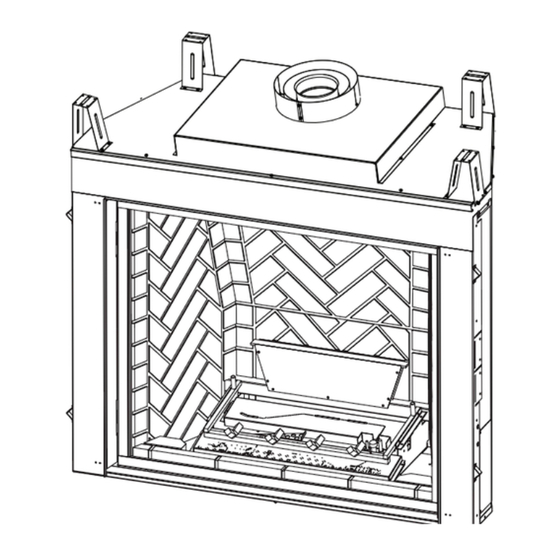
Page 6: Product Features
Figure 1 - For elevations above 4,500 feet (1,370 m) in USA, KHLDV Series Fireplace (shown with Millivolt) f i r e - p a r t s . c o m installations must be in accordance with the current ANSI Z223.1/NFPA 54 and/or local codes having jurisdiction. -
Page 7: Fireplace & Framing Dimensions
KHLDV Series Gas Fireplace FIREPLACE and FRAMING DIMENSIONS Min. Rough Opening Depth 1/2” or 5/8” P - Min. Rough Opening Width Min. Rough Opening Height Figure 2 - Fireplace and Framing Dimensions f i r e - p a r t s . c o m Ref. -
Page 8: Pre-Installation Information
PRE-INSTALLATION INFORMATION KHLDV Series Gas Fireplace BEFORE YOU START FIREBOX FRAMING Read this homeowner manual thoroughly and follow all Firebox framing can be built before or after the appliance instructions carefully. Inspect all contents for shipping is set in place. Refer to Figure 2 for fi rebox dimensions damage and immediately inform your dealer if any damage and framing. -
Page 9: Fireplace Location
KHLDV Series Gas Fireplace PRE-INSTALLATION INFORMATION FIREPLACE LOCATION Plan for the installation of your appliance. This includes determining where the unit is to be installed, the vent confi guration to be used, framing and fi nishing details, and whether any optional accessories (i.e. blower, wall switch, or remote control) are desired. -
Page 10: Clearances
KHLDV Series Gas Fireplace CLEARANCES CLEARANCES TO COMBUSTIBLES Follow these instructions carefully to ensure safe installation. Failure to follow in struc tions exactly can create a fi re hazard. The appliance cannot be installed on a carpet, tile or other combustible material other than wood fl... -
Page 11: Secure Fireplace To Floor Or Framing
KHLDV Series Gas Fireplace SECURE FIREPLACE to FLOOR or FRAMING The fi replace must be secured to the fl oor and/or to framing studs as shown in Figure 6. Use two (2) wood screws or masonry/ concrete screws to secure fi replace to the fl oor. -
Page 12: Venting Installation
VENTING INSTALLATION KHLDV Series Gas Fireplace Read all instructions completely and thoroughly before attempting installation. of p Failure to do so could result in serious injury, property damage or loss of life. Operation *3” of improperly installed and maintained **1”... -
Page 13: Installation Planning
KHLDV Series Gas Fireplace VENTING INSTALLATION INSTALLATION PLANNING There are two basic types of direct-vent installation: Never run the vent pipe down. This may cause excessive temperatures which could • Horizontal Termination cause a fi re. • Vertical Termination It is important to select the proper length of vent pipe for the type of termination you choose. -
Page 14: Termination Location
† A vent shall not terminate directly above a sidewalk or paved clearances tested and approved by the listing agency. driveway which is located between two single family dwellings and 3. Vermont Castings Group assumes no responsibility for serves both dwellings the improper performance of the appliance when the venting ‡... -
Page 15: Termination Clearances
KHLDV Series Gas Fireplace VENTING INSTALLATION TERMINATION CLEARANCES Termination clearances for buildings with combustible and non-combustible exteriors. Inside Corner Alcove Applications* Outside Corner Combustible 6" (152 mm) Combustible 6" (152 mm) Noncombustible 2" (51 mm) Noncombustible 2" (51 mm) Balcony -... -
Page 16: Vertical Sidewall Installation
KHLDV Series Gas Fireplace VENTING INSTALLATION VERTICAL SIDEWALL INSTALLATION - NOTE: Sealant is not required to assemble fi replace venting. Do not use silicone sealant at the inner fl ue exhaust connections. Step 1 Locate vent opening on the wall. It may be necessary to fi... -
Page 17: Vertical/Horizontal Termination Configurations
KHLDV Series Gas Fireplace VENTING INSTALLATION VERTICAL/HORIZONTAL TERMINATION 36" (914 mm) CONFIGURATIONS 24” Max. Since it is very important that the venting system (610 mm) maintain its balance between the combustion air intake and the fl ue gas exhaust, certain limitations as to vent confi... -
Page 18: Below Grade Installations
VENTING INSTALLATION KHLDV Series Gas Fireplace • Screws For each 45° elbow installed in the horizontal run, the length of the horizontal run MUST be reduced by 18" (45 cm). This does not apply if the 45° elbows are installed Firestop on the vertical part of the vent system. -
Page 19: Vertical Through-The-Roof Applications
KHLDV Series Gas Fireplace VENTNG INSTALLATION Restrictor Disc Snorkel Fireplace Collar Foundation Recess Wall Screws Watertight Seal Sheet Around Pipe Metal Screws Figure 19 - Figure 20 - Snorkel Installation, Recessed Foundation Install Restrictor Disc into Fireplace Collar • Do not back fi ll around snorkel. -
Page 20: Installation For Vertical Termination
VENTING INSTALLATION KHLDV Series Gas Fireplace For optimal fl ame appearance, a restrictor disk is necessary on straight vertical runs of 10' of more. • Runs may not incorporate elbows. • The disk is part number 56D3027 and is included in installation manual packet. -
Page 21: Termination Heights For Vents Above Flat Or Sloped Roofs
KHLDV Series Gas Fireplace VENTING INSTALLATION NOTE: If an offset is needed to avoid obstructions, you " must support the vent pipe every three (3) feet. Use wall " straps for this purpose. Refer to Page 18, Figure 21. Whenever possible, use 45° elbows instead of 90° elbows. -
Page 22: Fireplace Installation
KHLDV Series Gas Fireplace FIREPLACE INSTALLATION CHECK GAS TYPE Use proper gas type for the fi replace you are installing. 100 gallon (min) If you have confl icting gas type, do not install fi replace. Propane/LP External See dealer where you purchased the fi replace for proper... - Page 23 KHLDV Series Gas Fireplace FIREPLACE INSTALLATION A manual shutoff valve must be installed Only persons licensed to work with gas upstream of the appliance. Union tee piping may make the necessary gas and plugged 1/8" NPT pressure tapping connections to this appliance.
-
Page 24: Millivolt: Check Gas Pressure And Electrical Installation
MILLIVOLT: CHECK GAS PRES SURE AND ELECTRICAL INSTALLATION KHLDV Series Gas Fireplace CHECK GAS PRESSURE 1. Check gas type. The gas supply must be the same as stated on the appliance’s rating decal. If the gas supply is different from the fi replace, STOP! Do not install the appliance. -
Page 25: Millivolt: Remote Wall Switch Installation
KHLDV Series Gas Fireplace MILLIVOLT: REMOTE WALL SWITCH INSTALLATION REMOTE WALL MOUNTED SWITCH A remote wall switch and up to fi fteen (15) feet of 18 Ga. Do not connect wall switch to a wire may be used with this appliance. Attach the wall 110V circuit. - Page 26 MILLIVOLT: OPTIONAL FAN/BLOWER SYSTEM KHLDV Series Gas Fireplace Failure to replace the access cover with the one provided with the blower kit, and then running the blower, will cause excessive temperatures and could cause a fi re, property damage and/or 120V AC loss of life.
- Page 27 KHLDV Series Gas Fireplace MILLIVOLT: OPTIONAL FAN/BLOWER SYSTEM Blue Junction Box Blue Black Right Hi-Temp Blower Black Hi-Temp T-Stat Sensor Left Blower White Black Blower Rheostat Figure 34 - Blower Wiring Diagram Remove Solid Access Door f i r e - p a r t s . c o m...
-
Page 28: Millivolt: Operating Instructions
MILLIVOLT: OPERATING INSTRUCTIONS KHLDV Series Gas Fireplace FOR YOUR SAFETY READ BEFORE LIGHTING If you do not follow these instruction exactly, a fi re or explosion may result causing property damage, personal injury or loss of life. A. This appliance is equipped with a pilot which must be lit with built-in piezo ignitor while following these instructions exactly. -
Page 29: Lighting Pilot
KHLDV Series Gas Fireplace MILLIVOLT: OPERATING INSTRUCTIONS LIGHTING PILOT FOR THE FIRST TIME APPROVED LEAK TESTING METHOD You may check for gas leaks with the following methods only: • Soap and water solution NOTE: Remove any excessive pipe • An approved leak testing spray compound from the connections. -
Page 30: Lighting Burner
MILLIVOLT: OPERATING INSTRUCTIONS KHLDV Series Gas Fireplace LIGHTING BURNER MAIN BURNER SWITCH The “ON/OFF/RS” switch for the main burner can be found behind door of the fi replace. This switch allows you to turn on and to turn off the main burner without using the gas valve knob. -
Page 31: Signature Command: Check Gas Pressure And Electrical Installation
KHLDV Series Gas Fireplace SIGNATURE COMMAND: CHECK GAS PRESSURE and ELECTRICAL INSTALLATION CHECK GAS PRESSURE ELECTRICAL WIRING General 1. Check gas type. The gas supply must be the same as stated on the appliance’s rating decal. If the gas supply 1. -
Page 32: Electrical Installation
KHLDV Series Gas Fireplace ELECTRICAL INSTALLATION JUNCTION BOX WIRING WALL SWITCH INSTALLATION The wall switch wire connection is located off the 2 ft. wire 1. This should be done before framing the fi replace. Wire harness from the control box to the command center. Fig- the receptacle into an electrical circuit. -
Page 33: Signature Command Wiring Diagram
KHLDV Series Gas Fireplace ELECTRICAL INSTALLATION Light 300 Watt To Outlet A/C Module Pilot Optional Blower 300 Watt Rear Burner Solenoid 300 Watt Max RF Receiver A/C Module ON/OFF Button Control Board Black / Thermopile Red / Thermopile Sensor Conversion NG/LP f i r e - p a r t s . -
Page 34: Signature Command: Fan/Blower Systems
KHLDV Series Gas Fireplace SIGNATURE COMMAND: OPTIONAL FAN BLOWER SYSTEM BLOTKHLSC SIGNATURE COMMAND Electrical Grounding Instructions: This BLOWER appliance is equipped with a three-prong The BLOTKHLSC Blower Kit requires the SCSACM A/C (grounding) plug for your protection against Module and the TSFRSC remote to install and operate shock hazard and should be plugged directly this kit. -
Page 35: Signature Command: Operating Instructions
KHLDV Series Gas Fireplace SIGNATURE COMMAND: OPERATING INSTRUCTIONS FOR YOUR SAFETY READ BEFORE LIGHTING If you do not follow these instructions exactly, a fi re or explosion may result causing property damage, personal injury or loss of life. A. This appliance is equipped with an ignition device which automatically lights the pilot. Refer to the instructions. -
Page 36: Operating Instructions
SIGNATURE COMMAND: OPERATING INSTRUCTIONS KHLDV Series Gas Fireplace OPERATING INSTRUCTIONS 1. STOP! Read the safety information above. 2. This appliance is equipped with an ignition device which automatically lights the burner. Do not try to light the burner by hand. -
Page 37: Features
KHLDV Series Gas Fireplace SIGNATURE COMMAND SYSTEM OPERATION INSTRUCTIONS To Thermopile FEATURES RF Receiver ON/OFF To Sensor Command Center To Sparker • Easy Access Function Operation and System Confi g- uration NG/LP • Operation Confi rmation/Fault Diagnostic Indications Conversion (LED/Buzzer) •... -
Page 38: Key Combinations For System Settings
KHLDV Series Gas Fireplace SIGNATURE COMMAND SYSTEM OPERATION INSTRUCTIONS Either mode benefi ts from the instantaneous battery back- Remote Transmitter Learn Function (Default OFF) up, so you never have to worry about a power outage. 1. The RF receiver button located on the Control Board... -
Page 39: Functions/Operation
KHLDV Series Gas Fireplace SIGNATURE COMMAND SYSTEM OPERATION INSTRUCTIONS 2. Press the OFF button to decrease fl ame height. The fi rst FUNCTIONS/OPERATION (with Command two presses will decrease the fl ame height to medium Center) and low. Turning on the fi replace 3. -
Page 40: Touch Screen Remote Control Operation
TOUCH SCREEN REMOTE CONTROL OPERATION KHLDV Series Gas Fireplace Due to the sensitive temperature monitoring components in the transmitter, it is necessary to allow the transmitter to stabilize to room temperature before accurate room tempera- tures are displayed. If the transmitter is acti-... -
Page 41: Functions And Operations
KHLDV Series Gas Fireplace TOUCH SCREEN REMOTE CONTROL OPERATION Setting Privacy Code on Transmitter: Master Switch Figure 45 The remote transmitter privacy code is preset in factory. In the event of activation or interference from other near- by transmissions, change the code using the following... - Page 42 TOUCH SCREEN REMOTE CONTROL OPERATION KHLDV Series Gas Fireplace a. Push and hold the TIMER button for 3 seconds Or the fl ame height if none of the menu buttons (TIMER, THERMO, LIGHT, FAN, AUX) are b. Use the OFF/down buttons pressed and fl...
- Page 43 KHLDV Series Gas Fireplace TOUCH SCREEN REMOTE CONTROL OPERATION will automatically adjust the fl ame height according to the fi replace is on, the blower speed will take effect right difference between the Set temperature and the Room away; if the fi replace is off, the receiver will remember temperature.
-
Page 44: Safety Featuress
TOUCH SCREEN REMOTE CONTROL OPERATION KHLDV Series Gas Fireplace 3. Press the light button again to confi rm the setting. The 2. When the current setting is B), pressing TIMER button new setting will be transmitted to the receiver. and THERMO button at the same time for 3 seconds will switch to A) Mode. -
Page 45: Using The Mounting Base
KHLDV Series Gas Fireplace TOUCH SCREEN REMOTE CONTROL OPERATION USING THE MOUNTING BASE The transmitter comes with a mounting base which allows you to hang the transmitter on the wall. 1. Secure the mounting base on the wall with supplied screws. -
Page 46: Final Installation
FINAL INSTALLATION KHLDV Series Gas Fireplace GLASS FRAME REMOVAL NOTE: You must fi rst remove the safety barrier before you Each clamp has a quick spring force. When remove the glass frame. To remove the barrier, simply lift up reinstalling clamps, keep fi ngers clear. -
Page 47: Brick, Light Bulb And Lens Placement 400/500 Series
KHLDV Series Gas Fireplace FINAL INSTALLATION BRICK, LIGHT BULB, AND LENS PLACE- BRICK, LIGHT BULB, AND LENS PLACE- MENT— 400/500 SERIES MENT— 600 SERIES 1. Remove the trapezoidal light shroud located at the back 1. Remove safety barrier (if installed) by lifting up and out, of the fi... -
Page 48: Rock Wool Placement 400/500 Series
FINAL INSTALLATION KHLDV Series Gas Fireplace ROCK WOOL PLACEMENT — ROCK WOOL PLACEMENT— 600 SERIES 400/500 SERIES Place rock wool evenly in dime-sized pieces over front burner both in front and behind grate. For the rear burner, 1. Place rock wool on the front burner to provide glowing place the rock wool only on the carry-over areas between embers. -
Page 49: Log Placement 400/500 Series
KHLDV Series Gas Fireplace FINAL INSTALLATION LOG PLACEMENT— 400/500 SERIES LG593 LG595 Step 2 Burner Grate Assembly 1. Place the rear log over the grate toward the back by 3. Place the left front log in place by setting it over the left... - Page 50 KHLDV Series Gas Fireplace FINAL INSTALLATION LG599 Step 6 LG597 Step 4 5. Place the upper left log at angle over the rear and the 7. Place the upper right rear log over the rear log and the middle logs by matching the indentation on the bottom right upper log by matching the indentations located at f i r e - p a r t s .
-
Page 51: Log Placement 600 Series
KHLDV Series Gas Fireplace FINAL INSTALLATION Burner Grate Assembly Step 2 LOG PLACEMENT — 600 SERIES 3. Hold log #3 with the hole for the pin toward the back left corner. Position the log on the pin provided on the back 1. - Page 52 FINAL INSTALLATION KHLDV Series Gas Fireplace Log #5 Log #4 Steps 4 and 5 Finished log set with andirons 6. Hold log #6 in your right hand with the charred detail to the right and the notches on the bottom. Position the log on top of the keys provided on the top of log #5 in the front and log #3 in the back.
-
Page 53: Safety Barrier Installation Instructions
KHLDV Series Gas Fireplace FINAL INSTALLATION CERTIFIED DANGER AFETY ARRIER HOT GLASS WILL CAUSE BURNS. DO NOT TOUCH GLASS SAFETY BARRIER INSTALLATION UNTIL COOLED. INSTRUCTIONS NEVER ALLOW CHILDREN NOTE: A barrier designed to reduce the risk of burns TO TOUCH GLASS. -
Page 54: Cleaning And Maintenance
KHLDV Series Gas Fireplace CLEANING AND MAINTENANCE BURNER Turn off gas before servicing fi replace. It Inspect area around the injector. Remove any lint or foreign is recommended that a qualifi ed service material with a brush or vacuum. technician perform these check-ups at the... -
Page 55: Venting System
KHLDV Series Gas Fireplace CLEANING AND MAINTENANCE LOGS VENTING SYSTEM Leave logs installed in the fi replace for cleaning. Vacuum The fi replace and venting system should be inspected surface of the logs with a brush attachment. If logs must before initial use and at least annually by a qualifi... -
Page 56: Troubleshooting
TROUBLESHOOTING KHLDV Series Gas Fireplace STANDING PILOT IGNITION SYMPTOM POSSIBLE CAUSE ACTION 1. Spark ignitor will A. Open door and check to make sure wire is connected to A. Wire disconnected. not light pilot after ignitor. repeated triggering of B. Check for spark at electrode and pilot. If no spark and B. - Page 57 KHLDV Series Gas Fireplace TROUBLESHOOTING STANDING PILOT IGNITION CONTINUED SYMPTOM POSSIBLE CAUSE ACTION 4. Frequent pilot A. Pilot fl ame may be too high A. Clean and adjust the pilot fl ame for maximum fl ame outage problem. or too low, causing pilot impingement on thermocouple.
-
Page 58: Signature Command System
TROUBLESHOOTING KHLDV Series Gas Fireplace SIGNATURE COMMAND SYSTEM OPERATION FAULT ACTION DIAGNOSIS Using Battery polarity wrong? Re-install batteries battery? Make sure Command Install batteries and/or Battery voltage low? Change batteries Center and plug in the AC board No beep in about... -
Page 59: Replacement Parts
KHLDV Series Gas Fireplace REPLACEMENT PARTS FIREBOX COMPONENTS AND ACCESSORIES 12a,b 7a,b f i r e - p a r t s . c o m Item Description Qty. KHLDV400 KHLDV500 KHLDV600 Bulb (100 Watt) 73D0020 73D0020 73D0020 Bulb Socket... -
Page 60: Standing Pilot-Millivolt Control
KHLDV Series Gas Fireplace REPLACEMENT PARTS STANDING PILOT — MILLIVOLT CONTROL f i r e - p a r t s . c o m 11,12,13,14 20306742... - Page 61 KHLDV Series Gas Fireplace REPLACEMENT PARTS STANDING PILOT – MILLIVOLT CONTROL Item Description Qty. KHLDV400NV KHLDV400PV KHLDV500NV KHLDV500PV Gas Valve Assembly 37D0117 37D0118 37D0117 37D0118 Pilot Assembly 20H2048 20H2049 20H2048 20H2049 Replacement Thermocouple 37D1067 37D1067 37D1067 37D1067 Replacement Igniter w/wire...
-
Page 62: Signature Command System
KHLDV Series Gas Fireplace REPLACEMENT PARTS SIGNATURE COMMAND SYSTEM 400 Series Venturi Gasket Shield, Pilot 17, 18 Flex Hose 20H0022 500 Series Shield, Pilot f i r e - p a r t s . c o m Flex Hose... - Page 63 KHLDV Series Gas Fireplace REPLACEMENT PARTS SIGNATURE COMMAND SYSTEM KHLDV KHLDV KHLDV KHLDV KHLDV KHLDV Item Desc. Qty. 400NTSC 400PTSC 500NTSC 500PTSC 600NTSC 600PTSC Gas Valve Assembly 80D0001 80D0002 80D0001 80D0002 80D0001 80D0002 Pilot Assembly 80D0039 80D0040 80D0039 80D0040 80D0039...
-
Page 64: Logs
REPLACEMENT PARTS KHLDV Series Gas Fireplace LOGS KHLDV400 & KHLDV500 LOGS f i r e - p a r t s . c o m KHLDV600 LOGS Item Description Qty. KHLDV400 KHLDV500 KHLDV600 Log #1 73D0539 73D0200 20301946 Log #2... -
Page 65: Venting Components
KHLDV Series Gas Fireplace REPLACEMENT PARTS VENTING COMPONENTS f i r e - p a r t s . c o m 20306742... -
Page 66: Venting Components For 5" X 8
KHLDV Series Gas Fireplace REPLACEMENT PARTS VENTING COMPONENTS FOR 5" 8" Current Duravent Duravent or Vermont or Vermont Qty./ Castings Group Castings Group Selkirk Metal-Fab Item Description Part no. Part no. Part no. Part no. Horizontal Termination Cap w/Built-In Vinyl Siding BHR58TK9 Standoff Heat Defl... -
Page 67: Massachusetts Residents Only
MASSACHUSETTS RESIDENTS ONLY KHLDV Series Gas Fireplace Please read and follow these special requirements (30) day period, a battery operated carbon monoxide detector NOTE REGARDING VENTED PRODUCTS This product must be installed by a licensed plumber or with an alarm shall be installed. -
Page 68: Warranty
This warranty is expressly in lieu of other warranties, express or implied, including the warranty of mer- chantability of fi tness for purpose and of all other obligations or liabilities. Vermont Castings Group does not assume for it any other obligations or liabilities in connection with sale or use of the appliance. It states that do not allow limitations on how long an implied warranty lasts, or do not allow exclusion of indirect damage, those limitations of exclusions may not apply to you. -
Page 69: Effi Ciencies
Based on CSA P.4.1-09 EFFICIENCY RATINGS ENERGUIDE RATINGS FIREPLACE EFFICIENCY MODEL PERCENTAGE KHLDV400NV 69.6 KHLDV400PV 78.2 KHLDV400NTSC 73.2 f i r e - p a r t s . c o m KHLDV400PTSC 82.2 KHLDV500NV 75.2 KHLDV500PV 69.8 KHLDV500NTSC 78.5 KHLDV500PTSC 71.8 KHLDV600NTSC...
Need help?
Do you have a question about the KHLDV Series and is the answer not in the manual?
Questions and answers