
Related Manuals for Hommpa SKUF18494


Summary of Contents for Hommpa SKUF18494
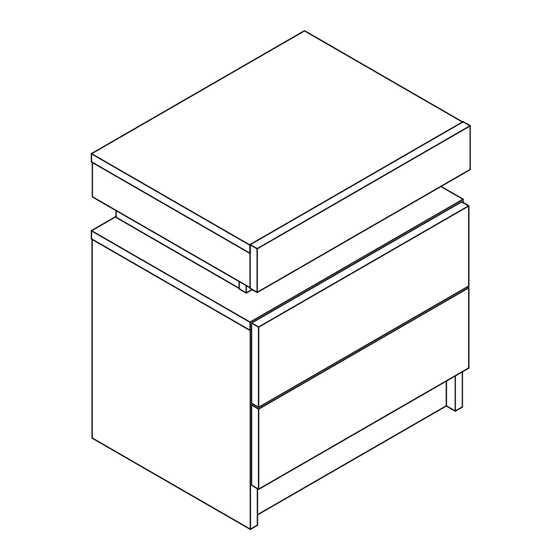
- Page 2 BEDSIDE TABLE SKUF18494...
- Page 3 ASSEMBLY INSTRUCTIONS 1 OF 22...
-
Page 4: Board Identification
BOARD IDENTIFICATION 2 OF 22... -
Page 5: Parts List
PARTS LIST 3 OF 22... - Page 6 4 OF 22...
- Page 7 STEP 1 - Install drawer track (E) & (F) to panel (9) & (10) with screws (D). Left Fix the pulley direction to the front Bottom track installation video Right 5 OF 22...
- Page 8 STEP 2 - Screw cam bolts (B) into panel (9) & (10) . - Insert wood dowels (K) into panel (4 - Insert wood dowels (C) into panel (9) & (10) . (Attention: Cam bolt & Insert nut need to be put together) Left Right 6 OF 22...
- Page 9 STEP 3 - Screw cam bolts (B) into panel (6) as below shown. - Insert wood dowels (C) into panel (11) as shown in the picture. (Attention: Cam bolt & Insert nut need to be put together) 7 OF 22...
- Page 10 STEP 4 - Attach panel (5) & (7) to (6) with cam locks (A). Right Left 8 OF 22...
- Page 11 STEP 5 - Attach panel (9) & (10) to (11) & (12) with cam locks (A). -Knock spikess (J) into panel (9) & (10) as below shown. Right Left 9 OF 22...
- Page 12 STEP 6 - Screw cam bolts (B) into panel (8) as below shown. (Attention: Cam bolt & Insert nut need to be put together) 10 OF 22...
- Page 13 STEP 7 - Insert panel (13) into the grooves. - Attach panel (8) to (9) & (10) with cam locks (A). - Lock the rebounder (G) to the panel (2) with the screw (E) . 11 OF 22...
- Page 14 STEP 8 - Attach panel (5) & (6) & (7) to (8) with cam locks (A). 12 OF 22...
- Page 15 STEP 9 - Stick LED band to the side of the panel. - Fasten the LED band with buckles. - Lock the rebounder (G) to the panel (1) with the screw (E) . 13 OF 22...
- Page 16 STEP 10 - Screw cam bolts (B) into panel (1) - Screw cam bol & (2) . - Insert wood dowels (C) into panel (1) & (3) & (4) . (Attention: Cam bolt & Insert nut need to be put together) Left Right 14 OF 22...
- Page 17 STEP 11 - Attach panel (3) & (4) to (1) with cam locks (A). Left Right 15 OF 22...
- Page 18 STEP 12 - Attach panel (2) to (1) & (3) & (4) with cam locks (A). - Screw cam bolts (B) into pa 16 OF 22...
- Page 19 STEP 13 - Attach panel (1) to (5) & (6) & (7) with cam locks (A). 17 OF 22...
- Page 20 STEP 14 - Screw cam bolts (B) into panel (14) as below shown. -Attach panel (17) to (15) & (16) with screws (K). (Attention: Cam bolt & Insert nut need to be put together) 18 OF 22...
- Page 21 STEP 15 - Insert panel (18) into the grooves. - Attach panel (14) to (15) & (16) with cam locks (A). 19 OF 22...
- Page 22 STEP 16 - Install drawer track (G) & (H) to panel (15) & (16) with screws (D). 20 OF 22...
- Page 23 STEP 17 -Connected power adapter to the RGB control box as below. -Specifications of battery:cr2025 3v -LED lamp with effective remote control distance of 5 meters √ CORRECT INCORRECT 1.Connect the light strip plug to the adapter socket correctly 2.Take out the remote control gasket 3.Align romote controller to the RGB Control box to adjust the color mode 21 OF 22...
- Page 24 STEP 18 - Insert the drawers. STEP 19 - Installation complete. 22 OF 22...
Need help?
Do you have a question about the SKUF18494 and is the answer not in the manual?
Questions and answers