
Related Manuals for Hommpa SKUE03045


Summary of Contents for Hommpa SKUE03045
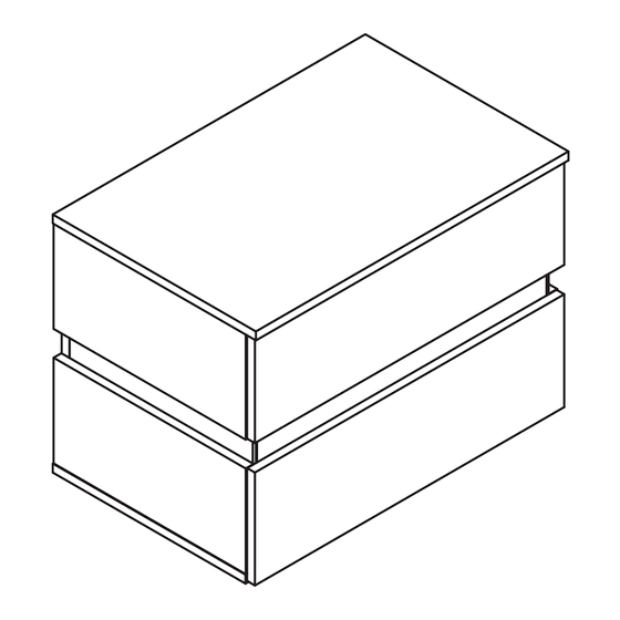
- Page 2 BEDSIDE TABLE SKUE03045...
- Page 3 ASSEMBLY INSTRUCTIONS Scan QR Code to view full assembly video 1 OF 21...
-
Page 4: Board Identification
BOARD IDENTIFICATION 2 OF 21... -
Page 5: Parts List
PARTS LIST 3 OF 21... - Page 6 4 OF 21...
- Page 7 STEP 1 - Attach panel (15) to (4) & (5) with screw. - Attach panel (15) to (6) & (7) with screw. 5 OF 21...
- Page 8 STEP 2 - Screw cam bolts (B) into panel (4) & (5) & (6) & (7) . - Insert wood dowels (K) into panel (4) & (5) & (6) & (7) . (Attention: Cam bolt & Insert nut need to be put together) 6 OF 21...
- Page 9 STEP 3 WARNING How To SEPARATE BALL BEARING SLIDE. 1) Pull toward arrow to open the slide until its stops and then flip it over. 2) Push plastic lever down and pull apart. OUTER TRACK INNER TRACK Align the outer track with the center of the inner track and push in. Three-section track installation video 7 OF 21...
- Page 10 STEP 4 - Install drawer track (C) to panel (4) & (5) & (6) & (7) with screws(E). Front Fasten the screws in the second hole in the front and the second hole in the rear of the drawer rail. The direction of the arrow is that the front is fixed on the plate.
- Page 11 STEP 5 - Stick LED band to the side of the back panel. - Fasten the LED band with buckles. 9 OF 21...
- Page 12 STEP 6 - Attach panel (4) & (5) & (6) & (7) to (3) with cam locks (A). 10 OF 21...
- Page 13 STEP 7 - Attach foot (J) to panel (2) with screw (F) . - Screw cam bolts (B) into panel (2) as below shown. - Screw cam bolts (B) into panel (2) as below shown. - Lock the rebounder (G) to the panel (2) with the screw (E) . (Attention: Cam bolt &...
- Page 14 STEP 8 - Attach panel (3) & (5) & (7) to (2) with cam locks (A). 12 OF 21...
- Page 15 STEP 9 - Screw cam bolts (B) into panel (1) as below shown. - Lock the rebounder (G) to the panel (1) with the screw (E) . (Attention: Cam bolt & Insert Rebound device installation video nut need to be put together) The direction of the arrow is mounted on the front.
- Page 16 STEP 10 - Attach panel (1) to (3) & (4) & (6) with cam locks (A). 14 OF 21...
- Page 17 STEP 11 - Screw cam bolts (B) into panel (10) & (12) as below shown. (Attention: Cam bolt & Insert nut need to be put together) Upper 15 OF 21...
- Page 18 STEP 12 - Attach panel (16) to (13) with screw (H) . - Screw cam bolts (B) into pa nel (13) as below shown. Lower (Attention: Cam bolt & Insert nut need to be put together) 16 OF 21...
- Page 19 STEP 13 - Attach panel (11) to (10) with cam locks (A). - Attach panel (8) & (9) to (10) with screw (L) . 17 OF 21...
- Page 20 STEP 14 - Insert panel (14) into the grooves. - Attach panel (12) & (13) to (8) & (9) & (11) with cam locks (A). Upper Lower 18 OF 21...
- Page 21 STEP 15 - Install drawer track (D) to panel (8) & (9) with screws(E). Fasten the screws in the second hole in the front and the second hole in the rear of the drawer rail. 19 OF 21...
- Page 22 STEP 16 -Connected power adapter to the RGB control box as below. -Specifications of battery:cr2025 3v -LED lamp with effective remote control distance of 5 meters √ CORRECT INCORRECT 1.Connect the light strip plug to the adapter socket correctly 2.Take out the remote control gasket 3.Align romote controller to the RGB Control box to adjust the color mode 20 OF 21...
- Page 23 STEP 17 - Insert the drawers. Upper Align the outer track with the center of the inner track and push in Lower STEP 18 - Installation complete. 21 OF 21...
Need help?
Do you have a question about the SKUE03045 and is the answer not in the manual?
Questions and answers