Table of Contents
Advertisement
Quick Links
Heating Solutions Ltd
Unit Heaters
Installation and Commissioning Manual
Models: Elite Pro Unit A/B/C/D 30, 40, 50, 60,
75, 90, 100, 115
Installer:
Please take time to read and understand these
instructions prior to any installation.
Installer must give a copy of this manual to the owner
Owner:
Keep this manual in a safe place in order to provide
your service technician with necessary information
WARNING
FIRE HAZARD
Keep all flammable objects, liquids and vapours the minimum
required clearances to combustibles away from the heater.
Some objects will catch fire or explode when placed close to
the heater.
Failure to follow these instructions can result in death, injury
or property damage
CBT00013-3 Elite Pro Unit Heaters Installation and Maintenance Manual July 2024
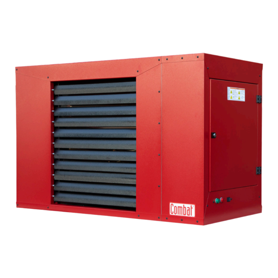
Elite Pro EPU Range
Warm Air Unit
Heaters
FOR YOUR SAFETY
If you smell gas:
•
Open windows
•
DO NOT try to light any appliance
•
DO NOT use any telephone in your building
•
Extinguish any open flame
•
Leave the building
•
Immediately call your local fuel supplier after
leaving the building.
•
Follow the fuel supplier's instructions
•
If you cannot reach your fuel supplier, call the
Emergency Services
WARNING
Improper
installation,
adjustment,
maintenance can result in death, injury or property damage.
Read the installation, operation and service manual thoroughly
before installing or servicing this equipment
Installation must be done by a registered installer / contractor
qualified in the installation and service of gas-fired heating
equipment or your gas supplier
Combat Heating Solutions Ltd
Unit 20 Red Mill Trading Estate
Rigby Street
Wednesbury
West Midlands
WS10 0NP
Tel:0121 506 7700
Email: uksales@combat.co.uk
alteration,
service
or
Advertisement
Table of Contents
Troubleshooting

Related Manuals for COMBAT Elite Pro EPU Series


Summary of Contents for COMBAT Elite Pro EPU Series
- Page 1 Combat Heating Solutions Ltd Unit 20 Red Mill Trading Estate Rigby Street Wednesbury West Midlands WS10 0NP Heating Solutions Ltd Tel:0121 506 7700 Email: uksales@combat.co.uk Elite Pro EPU Range Warm Air Unit Heaters Unit Heaters Installation and Commissioning Manual Models: Elite Pro Unit A/B/C/D 30, 40, 50, 60,...
-
Page 2: Technical Updates
Heating Solutions Ltd TECHNICAL UPDATES INFORMATION REGARDING UPDATES TO THIS MANUAL ARE LISTED BELOW AND SHOULD BE NOTED BEFORE COMMENCING WITH ANY INSTALLATION WORK. Date of Amendment Version No Page Description EPUA 30-60 Gas connection sizes changed from ¾ amended 16/05/2023 to ½... - Page 3 Heater Safety 11.5 EPUA Internal Wiring Diagram Manpower Requirements 11.6 EPUB, C & D internal wiring diagram Safety Labels Commissioning Installer Responsibility 12.1 Pre-Checks Laminated Wall Plate 12.2 Gas Supply Corrosive Chemicals 12.3 Mechanical Checks National Standards 12.4 Begin Commissioning Clearances to Combustibles 12.5 Combustion Testing...
- Page 4 Notified Body: Kiwa Gastec-0558 date 1 and Kiwa Gastec Product Approval Combat Heating Solutions Limited appliances have been tested and UKCA/CE certified as complying with the essential requirements of the Gas Appliance Directive, the Low Voltage Directive, the Electromagnetic Compatibility Directive and the Machinery Directive for use with natural gas when installed, commissioned and maintained in accordance with these instructions.
-
Page 5: Heater Safety
Heater Safety For additional copies of the Commissioning, Operation and Service Manual, or relevant burner and gas train manuals, please contact Combat Heating Solutions Limited. Email: uksales@combat.co.uk Web: www.combat.co.uk 1. Your Safety is Important to Us! 1.1 Manpower Requirements This symbol is used throughout the manual to notify To prevent personal injury and damage to the heater, a you of possible fire, electrical or burn hazards. -
Page 6: Installer Responsibility
2. Installer Responsibility WARNING To install the heater, as well as the fuel and electrical supplies, in accordance with applicable specifications and regulations. Combat Heating Solutions Limited recommends the installer contact a local building inspector, Fire Officer or insurance company for guidance. -
Page 7: Clearances To Combustibles
Clearances to Combustibles • Keep petrol or other combustible materials including WARNING flammable objects, liquids, dust or vapours away from this heater or any other appliance. • Do not spray aerosols in the vicinity of this appliance • The stated clearances to combustibles represent a surface temperature of 50°C (90°F) above room temperature. - Page 8 Clearances to Combustibles Heating Solutions Ltd Figure 3 Figure 2 3m Clear 0.6m 0.5m 0.5m* Heaters may be mounted at higher level if de-stratification fans and/or downflow heads are installed. The heater must always be installed at least 2.5m above the floor. The flue pipe must have clearance from combustibles by 5cm.
-
Page 9: Critical Considerations
Critical Considerations 4.1 Ventilation 4.3 Electrical Supply WARNING WARNING CARBON MONOXIDE HAZARD ELECTRICAL SHOCK HAZARD It is important to ensure that there is adequate air circulation Disconnect electric before service. around the heater to supply air for combustion, ventilation and This equipment must be properly earthed. -
Page 10: Specifications
Specifications Heating Solutions Ltd 5.1 EPUA Unit Heaters 4 X M10 captive nuts provided for connection of threaded support rod or similar Approximate position internally of outgoing air / overheat sensor Adjustable Outlet Louvres Heater Top View Access Door Lockout Reset Switch Red LED Green LED Approximate position externally of... - Page 11 Specifications 5.2 EPU Unit Heaters Dimension data EPUB, C & D EPU30 EPU40 EPU50 EPU60 EPU75 EPU90 EPU100 EPU115 EPUB height 1064 1064 1012 1012 EPUB depth 1051 1051 1112 1112 1112 1112 EPUC height 1177 1177 EPUD depth Inlet spigot height EPUC only Inlet spigot width EPUC only 1180 1180...
- Page 12 Specifications Heating Solutions Ltd 5.3 EPU Unit Heaters General technical data all EPUA30 EPUA40 EPUA50 EPUA60 EPUA75 EPUA90 EPUA100 EPUA115 models Maximum heat input Gross CV 36.75 48.6 58.3 71.3 85.7 107.7 Maximum heat input 33.10 43.78 48.01 64.23 77.20 97.02 107.20 120.72...
-
Page 13: Heater Installation
Heater Installation 6.1 General WARNING Heaters are designed for installation above 2.5m. These heaters must be installed within the heated space. Duct delivery systems are not permitted with axial fans. When handling or supporting the heater from below, ensure that the weight is taken at the support points. - Page 14 Heater Installation Heating Solutions Ltd M10 THREADED ROD M10 LOCKING NUT ENSURE ALL SUSPENSION M10 NUT HARDWARE IS TORQUED M10 WASHERS TO A MINIMUM OF 27Nm 1X INTERNAL 1X ON UNDERSIDE M10 NUT UNI-STRUT M10 LOCKING NUT M10 THREADED ROD CONE POINT PIN M10 LOCK NUT TOP OF HEATER...
-
Page 15: Flue Installation
Flue Installation 7.1 Flue Installation 7.3 Type B Appliance - Open Flue The flue must terminate outside of the building. Flues The flue must terminate outside the building and be and air intakes must be a fully sealed system and fitted with a low resistance terminal. - Page 16 Flue Installation Heating Solutions Ltd Figure 7 Open Flue Terminal Masterflash Flue sleeve by others, see flue installation section Roof Wall Vertical Flue Arrangement Flue Lengths Horizontal Flue Arrangement Open Flue Terminal Masterflash Flue sleeve by others, see flue installation section Note: Models Flue...
-
Page 17: Air Supply
Air Supply 8.3 Building Ventilation 8.1 Room Sealed Installation Where ventilation is required, air must be taken from an When installed as a room sealed heater, the air for outside point where it is not likely to be contaminated combustion is drawn in from outside the building. It is or obstructed. -
Page 18: Optional Configurations
Optional Configurations Heating Solutions Ltd 9.2 Recommended Ductwork Configuration 9.1 Distribution Ductwork for EPUB, C, D Heaters It is essential that the airflow in the duct system is EPUC heaters have the main distribution fan(s) at least that specified in the Data Sheet on Page 10 enclosed so that the heater may be connected to inlet/ Section 5.3 and in the correct direction across the heat outlet ducting. - Page 19 Gas Pipe 10.1 Connections IMPORTANT – The complete installation must be It is important that the gas supply pipe and the electrical purged and tested for soundness in accordance with connections do not support any of the heater’s weight. local and national regulations. A gas meter is connected to the service pipe by the Check the pipe and all fittings for leaks before placing gas supply company.
- Page 20 2 on the main plug at the heater. 11.2.2 Positioning Room Thermostats or Combat Control A room thermostat or Combat control should be mounted on a wall or column at a height of approximately 1.5 meters from the floor to measure the ambient temperature.
- Page 21 Wiring & Electrical Information 11.3 EPU to EPTC Wiring Diagram EPU to ELITE PRO TOUCH CONTROLLER WIRING DIAGRAM LOC OUT RE ET WITCH INDICATOR WITCH...
- Page 22 Heating Solutions Ltd 11.4 EPU to Enercal Wiring Diagram Remote Sensor Wire Link ENERCAL SPACE10 CBT0013-3 ELITE PRO UNIT HEATERS INSTALLATION AND SERVICING MANUAL JULY 2024...
- Page 23 Wiring & Electrical Information 11.5 EPUA Internal Wiring Diagram...
- Page 24 Wiring & Electrical Information Heating Solutions Ltd 11.6 EPUB, C & D Internal Wiring Diagram CBT0013-3 ELITE PRO UNIT HEATERS INSTALLATION AND SERVICING MANUAL JULY 2024...
-
Page 25: Operation
Commissioning On heat demand: 12.1 Pre-Commission Checks When the thermostat contacts are closed, and the All pre-commission checks must be carried out before heater is not in a lockout condition the programmed lighting the heater. sequence commences. Ensure that the heater and all controls are suitable for If the heater is in lockout, then it must be reset as the gas and electrical supply to which they are to be described below, before the control sequence can be... - Page 26 Commissioning Heating Solutions Ltd 12.5 Combustion Testing, Gas Rate and Inlet 12.5.4 Turning Off the Heater working Pressure Remove the test jumper on Con 30 and place in the To ensure the heater is running at either maximum or park position, ensuring the external controls are in the minimum heat output (burner modulation), it can be off position, the main burner will stop.
-
Page 27: Lighting Instructions
User Instructions 13.1 User Instructions 13.4.2 Turning Off the Heater The Elite Pro Unit Heater is fully automatic and operated Set the installed remote controls to the “OFF” from the external controls fitted on site. The only user position. The burner will turn off automatically. control at the heater is the: Remote Lockout Reset The fan will continue to run for a few minutes. - Page 28 Combat Heating Solutions Limited and ceramic insulators. Replace as necessary conform to all requirements set forth in the Combat manuals and all applicable governmental authorities 14.3 Fan/Motor Assembly pertaining to the installation, service, operation and The main fan bearings are permanently sealed and do labelling of the equipment.
- Page 29 Air distribution fan manual. Product safety signs or labels should be replaced by the product user when they are Safety labels no longer legible. Please contact Combat Heating Solutions Limited or your Combat independent distributor to obtain replacement signs or labels.
-
Page 30: Troubleshooting
Troubleshooting Heating Solutions Ltd 15.1 General Figure 15.1.1 Red Light Fault Indicator Chart The section has troubleshooting flowcharts from pages The red light on the heater can also be used to identify if 31-33 that have detailed descriptions of potential faults there is a fault with the heater. -
Page 31: General Troubleshooting Chart
& off 3. Combustion fan fault permanently on? every second? 4. Loss of flame signal Heater in Hold down black reset permanent lock Call Combat at switch on out: 01215067700, heater for at least 3 DOESN'T Remove main DOESN'T... - Page 32 Check wiring connection & condition, Check condition & replace PCB if necessary. From data connection of Tachometer: plate note the model & test number, contact uksales@combat.co.uk On PCB CON 21 Modulation: sensor, replace if (bottom right, 4 Is there 1V -...
- Page 33 PCB if necessary. From data SAME plate note the model & test number, air temperature, sensor is contact uksales@combat.co.uk damaged or faulty 15.2.4 Remote Fan Switch Main Distribution Fan Troubleshooting Check condition & Check: Wiring, mains supply, & if...
- Page 34 Troubleshooting Heating Solutions Ltd 15.3 NTC Sensor Resistance vs Temperature Graph If the temperature of the outlet air is higher than the set The EPU heaters have inlet and outlet NTC temperature limit, the heater will turn off, cool down, and turn back sensors.
-
Page 35: Removal And Replacement Of Parts
Ensure both gas and electrical supplies are correctly isolated before attempting to remove the gas valve. The Gas valve is Factory set by Combat Heating Solutions and should not be adjusted. Replace in reverse order. Verify that the gas flow direction of the valve is correct. - Page 36 Removal & Replacement of Parts Heating Solutions Ltd Burner assembly for models 75-115 Inlet pressure test point Inlet pressure Inlet pressure test point test point EPU Parts Table Description 90034100- 90034100- 90034100- 90034100- 90034102- 90034102- 90034102- 90034102- Gas valve 3040P 3040P 5060P 5060P...
- Page 37 Removal & Replacement of Parts 16.2 Ignition Electrode To replace the Ignition/Flame sensor electrode remove 7mm +/- 1.0mm the burner gas valve assembly and the access cover. Disconnect the HT cable and remove the 2 fixing screws through the access holes. Withdraw the Electrode through the access cover.
- Page 38 Strictly comply with the colour code of the fan wires to ensure correct operation. • Use only genuine replacement parts sold and supplied by Combat Heating Solutions Limited. • The three-speed winding connections are: The axial fan unit for the heater is supplied completely •...
-
Page 39: Centrifugal Fan Orientation
Axial fan Axial fan Axial fan EUA models 500mm 500mm 550mm 550mm 500mm 500mm 550mm 550mm Combat P/n 90776001-P 90776001-P 90776000-P 90776001-P 90776001-P 90776001-P 90776000-P 90776000-P Quantity Fan rating (Watts per fan) Centrifugal fan Torin Torin Torin Torin Torin Torin... -
Page 40: Fire Hazard
Installation Code and Annual Inspections: All installations and service of Combat equipment must be performed by a contractor qualified in the installation and service of equipment sold and supplied by Combat HEATING SOLUTIONS Limited and conform to all requirements set forth in the Combat manuals and all applicable governmental authorities pertaining to the installation, service and operation of the equipment.
Need help?
Do you have a question about the Elite Pro EPU Series and is the answer not in the manual?
Questions and answers