
Subscribe to Our Youtube Channel
Related Manuals for COMBAT ECO20A


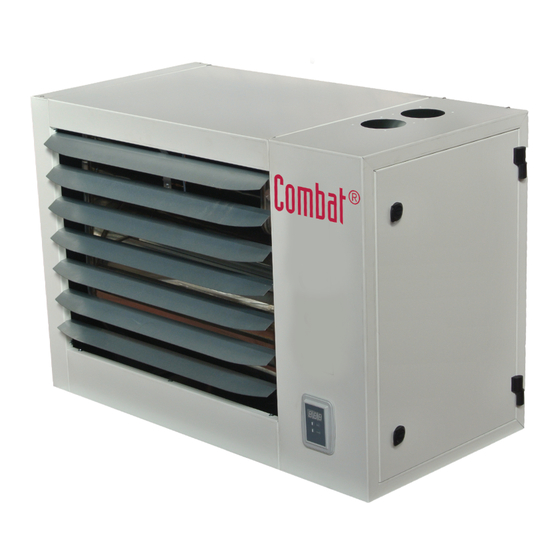
Summary of Contents for COMBAT ECO20A
- Page 1 Operating, Installation and Maintenance Manual CONDENSING WARM AIR HEATER ECO code HG0140.00GB-M ed.A-1507...
- Page 2 WARM AIR HEATER ECO Declaration of Conformity COMBAT HVAC LIMITED Unit A, Kings Hill Business Park Darlaston Road, Wednesbury West Midlands, WS10 7SH UK Telephone: 0121 506 7700 Fax: 0121 506 7701 www.combat.co.uk With this document we declare that the unit:...
- Page 3 WARM AIR HEATER ECO code HG0140.00GB-M ed.A-1507...
- Page 4 WARM AIR HEATER ECO code HG0140.00GB-M ed.A-1507...
-
Page 5: Table Of Contents
WARM AIR HEATER ECO INDEX SECTION 1. GENERAL CAUTIONS ..............6 SECTION 2. SAFETY INSTRUCTIONS ............. 6 Fuel ....................6 Gas Leaks ..................6 Power Supply ................. 7 Operation ..................7 Maintenance .................. 7 Transport and Handling ..............7 Packaging ..................7 SECTION 3. -
Page 6: Section 1. General Cautions
If you smell gas: The warranty conditions for this equipment can be found in the • do not operate electrical switches, telephones or any other Combat HVAC Limited Terms and Conditions Of Sale object or device that could produce sparks; • immediately open doors and windows to create an air flow Reference standards (only applies to Italy): to vent the gas out of the room;... -
Page 7: Power Supply
WARM AIR HEATER ECO 2.3. Power supply If the equipment is not used for long periods, shut the gas sup- ply off through the gas shut off valve and disconnect it from The equipment must be correctly connected to an effective the power supply. -
Page 8: Section 3. Technical Features
WARM AIR HEATER ECO TECHNICAL FEATURES Inherent Safety The performance increase at minimum power is achieved by The ECO series modulating warm air heaters have been de- using a sophisticated air/gas mixing technique and by adjusting signed for industrial and commercial environments. at the same time the combustion air and the fuel gas. -
Page 9: Technical Data
WARM AIR HEATER ECO 3.1. Technical Data Model: ECO20A ECO34A ECO45A ECO65A ECO80A ECO105A Type of equipment B23P - B53P - C13 - C43 - C53 - C63 EC certification PIN. 0476CQ0451 NOx Class Heater Performance Burner heat output (Hi) 4.75 19.00 7.60 34.85 8.50... -
Page 10: Dimensions
WARM AIR HEATER ECO 3.2. Dimensions HG0140.00_C2_001 HG0140.00_C2_001 HG0140.00_C2_001 HG0140.00_C2_001 Mod. Overall dimensions Inlet Shelf Supply GAS Packaging ØG ECO20A ECO34A 1080 ECO45A 1080 3/4'' ECO65A 1310 1010 1410 ECO80A 1515 1180 1610 1040 ECO105A 1740 1410 1810 1040 code HG0140.00GB-M ed.A-1507... - Page 11 WARM AIR HEATER ECO HG0140.00_C2_001 HG0140.00_C2_001 Mod. Mod. Vertical drains (OPT.) Horizontal exhausts (STD) ECO20A ECO20A ECO34A ECO34A ECO45A ECO45A ECO65A ECO65A ECO80A ECO80A 100* 100* 100* 100* ECO105A ECO105A * Obtained by using adaptors supplied as standard. * Obtained by using the adaptors supplied as standard.
-
Page 12: Section 4. User's Instructions
• A time and temperature thermostat control such as will be lit with an ignition power of approximately 50% of the the Combat HVAC NRG Control, with a clean contact to maximum power. Once the flame stabilising time has expired, be connected to the PCB ID2/IDC2 terminals; the burner will start to modulate its heat output according to the •... - Page 13 WARM AIR HEATER ECO Operation with a SmartControl chronothermostat Safety thermostats G20800IT ECO heaters are fitted with a safety thermostat with automatic reset and positive safety setting. A safety operation of this ther- The control operates as a chronothermostat and can be used mostat occurs when its sensitive component is broken. as a monitoring device for a single zone system at the same temperature, where up to 32 heaters can be installed simultane- When the thermostat is operated, through the flame monitor-...
-
Page 14: Interface Panel
WARM AIR HEATER ECO 4.3. Interface Panel the menu and go back to the "machine status" display. To change the parameter, press the arrow keys: pressing ↑ (up The ECO heaters are fitted as standard with a multifunction arrow) increases the parameter by 1, pressing ↓ (down arrow) LCD panel located on the front panel of the suspended heater, reduces it by 1. -
Page 15: Reset
WARM AIR HEATER ECO 4.4. Reset Second and third level menus The second and third level menus are reserved to the Service The modulation PCB allows the operator to identify more than Centre and can be accessed only by entering a password, thirty different causes of lockouts. -
Page 16: Set-Up
WARM AIR HEATER ECO 4.5. Set-up ---------------------------------------------------------------------------------- NOTE: The remote NTC temperature probe is an optional The ECO heaters have three heat output regulation modes: external probe (code G07202); not to be mistaken for the • 0/-10 Vdc modulation probe NTC1. •... -
Page 17: Section 5. Installation Instructions
The codes for the available shelves are: Where ventilation is required, air must be taken from an G27900 Fixed shelf kit for ECO20A-65A; outside point where it is not likely to be contaminated or G27820 Rotating shelf kit for ECO20A;... - Page 18 WARM AIR HEATER ECO Fixed shelves Suspended heater To install the fixed shelves to the walls: ECO20A-80A HEATERS: To install a suspended heater by • fix it to the wall and level the bracket with a spirit level: using eyebolts, tie rods or chains, a kit containing supporting --------------------------------------------------------------------------------- pins is available, as an accessory; its code is: G27880. This kit...
-
Page 19: Condensation Drainage
• risk of fumes discharged from the condensate drain. has an acidity of 3.5-3.8 PH. On request, Combat can supply the kit (G14303) required to Build up of condensation in the heat exchanger neutralise the condensation; the kit consists of: During normal operation, condensate must not be allowed to •... -
Page 20: Connections To The Flue
ECO heater used; each component has a different COMBAT sells certified i ntake o r e xhaust t erminals that pressure drop value as the glue gases flow rate is different. must therefore be bought together with the heaters. - Page 21 WARM AIR HEATER ECO NOTE: Values calculated on the flue mass flow rate achieved with natural gas G20. Installing the terminals ---------------------------------------------------------------------------------- The ECO heaters are fitted with a top and bottom provision for NOTE: The terminals are supplied with silicone seals; on air inlet and flue exhaust. request a kit with EPDM seals can be requested. According to installation requirements, the terminals can be ---------------------------------------------------------------------------------- fitted at the back or at the top.
- Page 22 A wall fitted terminal, exhaust only. Fumes OUT Ø80 pipes and bends: TB23-08-HS0 Mod. 105A Ø100 pipes and bends: TB23-10-HS0 + G15815-08-10 (ec- HG140.00_IM_021 centric adapter only for mod. ECO20A-65A) Mod. 105A Fumes OUT Fumes OUT Vertical B23 terminal Open combustion circuit, combustion air intake from the room and exhaust to the outdoor. Standards UNI-CIG 7129 and 7131 require the provision of suitable vents on the walls.
- Page 23 ---------------------------------------------------------------------------------- Air IN Ø80 pipes and bends: TB23-08-VSW + TB23-08-HS0 Mod. 105A 30+30 20+20 15+15 HG140.00_IM_026 Fumes OUT Ø100 pipes and bends: TB23-10-VSW + 2xG15815-08-10 + TB23-10-HS0 (adaptor only for mod. ECO20A-65A) Mod. 105A 30+30 25+25 15+15 10+10 1max 2max Air IN HG140.00_IM_027 code HG0140.00GB-M ed.A-1507...
- Page 24 Ø80 pipes and bends: TC13-08-HC1 HG140.00_IM_025 Mod. 105A 30+30 30+30 15+15 Ø100 pipes and bends: TC13-10-HC2 + 2xG15835-08-10 (ec- 2max centric adaptors only for mod. ECO20A-65A) Mod. 105A 30+30 15+15 Ø130 pipes and bends: TC13-13-HC5 + 2xG15815-10-13 + 2xG15810-13-45 (adaptors and bends only suitable only for model ECO80A-105A) Mod.
- Page 25 Ø80 pipes and bends: TC33-08-VC1K 2max 1max Mod. 105A 2max 1max 30+30 10+10 Ø100 pipes and bends: TC33-10-VC2K + 2xG15835-08-10 (eccentric adaptors only for mod. ECO20A-65A) Mod. 105A 30+30 30+30 15+15 HG140.00_IM_028 HG140.00_IM_029 Ø130 pipes and bends: TC33-13-VC5K +2xG15815-10-13 + 2xG15810-13-45 (adaptors and bends only suitable only for model ECO80A-105A) Mod.
-
Page 26: Electrical Connections
WARM AIR HEATER ECO 5.5. Electrical Connections Power supply The heater must be correctly connected to an effective earthing system, fitted in compliance with current legislation. Single phase 230VAC power supply with neutral; do not swap the neutral with the live wire. For safety reasons, the flame monitoring device prevents opera- tion if phase and neutral are swapped, fault F1X. The heater can be connected to the mains power supply with a single plug-socket only if the latter does not allow swapping the live with the neutral. - Page 27 WARM AIR HEATER ECO SmartControl Connection Summer ventilation To enable the fans only (summer ventilation with burner off), The SmartControl must be connected by using the connector provided. Connect the power supply, making sure polarity is three types of controls are available: correct. • the ID3-IDC2 contact; Connect the RS485 network to its terminals, making sure po- •...
-
Page 28: Modulation Pcb Parameters
All values of the parameters of the CPU-SMART PCB are shown for all ECO heater models. parameters that could be modified with 001 Password; parameters that could be modified with a Password which can be requested to the manufacturer's Service Centre; parameters that could be modified with a Smart Control or modbus. CPU-SMART PCB version 7.01.xx Parameters PARAMETER DESCRIPTION ECO20A ECO34A ECO45A ECO65A ECO80A ECO105A Setting parameters Flame modulation: 2=NTC1; 5=0÷10Vdc; 7=Modbus (SmartControl and PID) Type of equipment: 0=heater; 2=boiler; 5=PCH Remote lockout signal output (Q1): 0=disabled; 1=enabled Fan ON delay time (RL2): 0÷255 30 (=150 sec) Fan OFF delay time (RL2): 0÷255 (1=5sec 60=300 sec) - Page 29 WARM AIR HEATER ECO CPU-SMART PCB parameters version 7.01.xx PARAMETER DESCRIPTION ECO20A ECO34A ECO45A ECO65A ECO80A ECO105A 0/10 Vdc - D0=5 control Active only with D0=5 (0/10V) 0=modulation only; 1=modulation and ON/OFF Voltage OFF; burner off if H51=1 Delta voltage for burner ON Bottom input time on: 0÷255 Top input time on: 0÷255...
- Page 30 WARM AIR HEATER ECO CPU-SMART PCB version 7.01.xx Parameters PARAMETER DESCRIPTION ECO20A ECO34A ECO45A ECO65A ECO80A ECO105A Hydraulic circuit WATER FLOW monitoring - NOT USED ON LP and LK Flow sensor B3 output enabling: 0=disabled 1=enabled as ON/OFF input without F85 fault autoreset...
-
Page 31: Analysis Of Lockouts- Faults
WARM AIR HEATER ECO 5.7. Analysis of lockouts- faults The CPU-SMART manages two types of lockouts: • preventive, it warns the customer that the ECO heaters require maintenance; • operational, it stops the ECO heater for safety reasons or to ensure its correct operation. Some operational faults require manual resets;... - Page 32 WARM AIR HEATER ECO FAULT DESCRIPTION CAUSE RESET NTC probes broken or missing Probe NTC1 error, air intake tempera- No signal from probe or broken probe Auto-reset ture Over-temperature • The minimum heat output of the heater is over- The temperature of the air intake probe sized compared to the heat output required by Auto-reset NTC1>TH1...
-
Page 33: Section 6. Gas Connection
WARM AIR HEATER ECO GAS CONNECTION --------------------------------------------------------------------------------- NOTE: For a correct maintenance, connect the heater by Use the gas line connections only with EC certified components means of a seal and swivel gasket. --------------------------------------------------------------------------------- The heater is supplied complete with: Avoid using threaded connected directly on the gas connection. - a dual gas valve;... -
Page 34: Section 7. Servicing Instructions
WARM AIR HEATER ECO SERVICING INSTRUCTIONS The first start-up must be carried out only by authorised service centres. The first start-up also includes a combustion analysis, which is compulsory. The equipment is certified in the EC and non-EC countries, according to the gas categories shown below. 7.1. Country table - gas category Country Category Pressure Pressure AT, CH II2H3B/P 20 mbar G30/G31 50 mbar BE <70kW I2E(S)B, I3P G20/G25 20/25 mbar 37 mbar BE >70kW I2E(R)B, I3P G20/G25 20/25 mbar 37 mbar II2ELL3B/P G20/G25... -
Page 35: Gas Settings Table
WARM AIR HEATER ECO 7.2. Gas settings table TYPE OF GAS G20 TYPE OF EQUIPMENT ECO20A ECO34A ECO45A ECO65A ECO80A ECO105A CATEGORY according to the country of destination - see reference table GAS SUPPLY PRESSURE [mbar] 20 [min 17-max 25] * Ø... - Page 36 WARM AIR HEATER ECO TYPE OF GAS G2.350 (only for HU-Hungary) TYPE OF EQUIPMENT ECO20A ECO34A ECO45A ECO65A ECO80A ECO105A* CATEGORY according to the country of destination - see reference table GAS SUPPLY PRESSURE [mbar] 25 [min 20-max 33] * Ø PILOT NOZZLE [mm] 0.70 GAS CONSUMPTION 0.59 2.33 0.93 4.29 1.04 5.16 1.52 7.99 2.01 10.1 2.21 12.3...
- Page 37 WARM AIR HEATER ECO TYPE OF GAS G31 TYPE OF EQUIPMENT ECO20A ECO34A ECO45A ECO65A ECO80A ECO105A CATEGORY according to the country of destination - see reference table GAS SUPPLY PRESSURE [mbar] 30 [min 25-max 35] - 37 [min 25-max 45] - 50 [min 42.5-max 57.5] Ø...
-
Page 38: Configuring With Lcd Display
0/100 for currents Par menu. This password is used by service staff and from 0 to 2 microamperes, 100 over 2 microamperes. must be requested from Combat. See Paragraph 5.6 "Modulation PCB Parameters". Flt Menu If no keys are pressed for 10 minutes after entering the pass- It displays error history. -
Page 39: Starting Up For The First Time
Paragraph 7.2 "GAS Connections Tables". pipe. This will lock out the equipment. ---------------------------------------------------------------------------------- You will need to reset the equipment and repeat the opera- tion until it ignites. ---------------------------------------------------------------------------------- For models: ECO20A-80A For models: ECO105A OFFSET adjustment screw Pressure connector OFFSET (Pascal) Gas intake pressure... -
Page 40: Conversion To Lpg
• reconnect to the electrical mains and set the heater up for ignition; • while the start-up electrode is sparking, make sure there are no gas leaks. For models: ECO20A-80A For models: ECO105A Gaskets Gaskets Calibrated GAS orifice plate Calibrated GAS orifice plate code HG0140.00GB-M ed.A-1507... -
Page 41: Conversion To Gas G25 - G25.1
WARM AIR HEATER ECO 7.7. Conversion to gas G25 - G25.1 7.8. Conversion to gas G2.350 Conversion for gases from G20 to G25 is allowed only in Conversion is allowed only for Poland. countries of category II2ELL3B/P [Germany] and category Conversion from one type of gas to another can only be per- II2HS3B/P [Hungary]. -
Page 42: Replacing The Gas Valve
ECO105A The Smart Control can be used to access all parameters [see tables on previous pages]; parameters have passwords, which are issued by the Combat Technical Service Depart. Please refer to the Smart Control manual for instructions for the procedure for access and modification of functional parameters. -
Page 43: Section 8. Maintenance
WARM AIR HEATER ECO MAINTENANCE 2) Inspection of flue exhaust and air intake ducts Visually inspect where possible or examine with specific tools to To keep the machine efficient and guarantee a long lifetime of check the condition of the ducts. the heater, it is advisable to run some inspections every year, Remove dust that forms on the air intake terminal. before turning it on for the season: 1) check the status of the start-up electrodes, detection elec- 3) Inspection and cleaning the venturi... -
Page 44: Section 9. Wiring Diagrams
WARM AIR HEATER ECO WIRING DIAGRAM Wiring diagram ECO20A/ECO105A (code JG0350.00) code HG0140.00GB-M ed.A-1507... -
Page 45: Section 10. List Of Spare Parts
WARM AIR HEATER ECO LIST OF SPARE PARTS 10.1. Parts for the electrical panel CPU PCB case G16881 Base G16882 Cover ModBus Connector G10054 Connector Burner Fan Modulation CPU-SMART Display cable G10054 G16791 ON/OFF Connector NTC1 Connector G10051 G04763 ALARM Connector G10052 CPU-SMART PCB G16800.01... -
Page 46: 10.2. Parts For The Burner Unit
WARM AIR HEATER ECO 10.2. Parts for the burner unit Gas valve Venturi gas valve Pilot solenoid valve G14067 ECO20A-80A G14898 ECO20A G14378 For all models G14456 ECO105A G14990 ECO34A G16219 ECO45A G14154 ECO65A-80A Butterfly gasket G14154.08 ECO105A 2x X01133 For all models... -
Page 47: Code Hg0140.00Gb-M Ed.a
Condense trap complete with condensation detection electrode G27810 For all models condense trap pipe G27576 For all models Condensation detection electrode G27806 For all models Tabs Cover G27582 no.7 ECO20A X04511 G27583 no.7 ECO34A For all models no.8 ECO45A no.18 ECO105A Hinges G27585 no.8... - Page 48 WARM AIR HEATER ECO Combat HVAC Limited Unit A, Kings Hill Business Park Service Telephone: 0121 506 7709 Darlaston Road, Wednesbury Service Fax: 0121 506 7702 West Midlands, WS10 7SH UK E-mail: uksales@combat.co.uk Telephone: 0121 506 7700 E-mail: export@combat.co.uk Fax: 0121 506 7701 www.combat.co.uk...
Need help?
Do you have a question about the ECO20A and is the answer not in the manual?
Questions and answers