
Related Manuals for COMBAT FRSA


Summary of Contents for COMBAT FRSA
- Page 1 Room Sealed Unit Heaters Models FRSA, FRSB, FRSC & FRSD 75 - 210 Installation, Commissioning, Service & User Instructions August 2000 Part No. X224B...
- Page 3 ROOM SEALED UNIT HEATERS These appliances have been tested and certified as complying with the essential requirements of the Gas Appliance directive, The low voltage directive ,The Electromagnetic Compatibility Directive and the Machinery Directive for use on natural gas and L.P.G gas when installed , commissioned and maintained in accordance with these instructions.
-
Page 4: Table Of Contents
ROOM SEALED UNIT HEATERS Contents The parts of this manual are numbered by section, clause and sub clause. Hence 1:2:3 refers to section I clause 2 sub clause 3. Figure numbers also follow this notation. Hence Fig. 2:3 is section 2 Fig. 3. Section 1. -
Page 5: General Specification
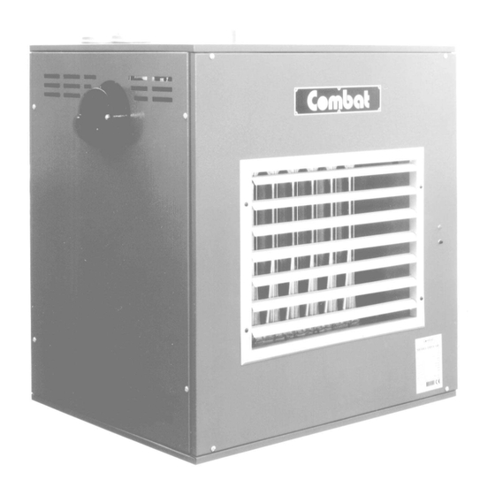
General Specification Basic Information COMBAT® FRSA, FRSB, FRSC & FRSD ranges of unit air heaters are type C32 appliances for vertical flue terminals and C12 for horizontal flue terminals both of which have room sealed combustion and fan assisted flues. They are designed to be suspended or shelf mounted, and are produced in an 8 size range from 27 kW (92,124 Btu/hr) to 76 kW (259,312 Btu/hr) heat input (Gross CV). - Page 6 Rear GREEN - Burner On RED - Lockout Lockout Reset Button Data Plate Lighting Instructions Fig. 1.1 General Arrangement - FRSA Models Dimension Data (see Figs.1.2 to 1.4 - Dimension Diagrams) Model 'A' - Width 1055 1055 1195 'B' - Width between hanging points...
- Page 7 Hanging Points Front * Note: FRSD models are fitted with an air outlet spigot as standard. All inlet and outlet duct spigots are complete with 25mm mez. flange. Fig.1.4 Side View Dimensions FRSA FRSB 510 Centres 510 Centres 1211 (except Models 150 & 170: 1177)
- Page 8 / ³ t Note: for FRSD ducted units sold without fans, the air flow provided by the system must be able to produce at least the lower of the air flows of the FRSA or the FRSB heater of the same model.
- Page 9 TABLE 2.2 BURNER DATA II2 H 3+ G20 H GAS / u t / u t / u t L.P.G. II2H 3+ / u t / u t / u t q i l h / l q i l h / l Appliance Category II Propane Gas Inlet pressure 37 mbar (25 - 45)
- Page 10 ROOM SEALED UNIT HEATERS Gas Controls The heaters will be fitted with S.I.T Nova gas control valves. Main Gas Control Valve - Natural Gas The multifunctional main gas valve contains two automatic shut off valves. When set up as defined in Section 4 the valves will have a step or slow opening operation on the main gas, to give smooth lighting.
- Page 11 ROOM SEALED UNIT HEATERS WARNING: IT IS ESSENTIAL THAT THE BREAK OFF LINK SHOWN IS REMOVED IN THE EVENT OF THERMOSTAT REPLACEMENT Fig. 2.4 Combination Fan/Limit Thermostat Fig. 2.5 Satronic DMG 970 MOD 03 Control Box Sequence Page 9...
- Page 12 ROOM SEALED UNIT HEATERS Burner Control Box 2.4.1 Description (DMG 970 MOD 03 CONTROL BOX) The fully automatic gas burner fitted to all models is controlled by a Satronic DMG 970 MOD 03 plug-in control box. This control ensures the safe start and stop sequence and also monitors the safe presence of a flame and operation of the flue fan.
-
Page 13: Heater Installation
ROOM SEALED UNIT HEATERS Section 3. Heater Installation Required Standards It is important that all gas appliances are installed by competent persons, in accordance with the relevant requirements of the local laws and regulations. Failure to install gas appliances correctly could lead to prosecution. - Page 14 ROOM SEALED UNIT HEATERS Gas Supply General The installation must comply with local laws and regulations, and the complete installation including the meter must be purged and tested for soundness. The gas supply must be via metal pipes and terminate at the heater with a manual gas valve of the 90º turn type and union as in Fig.
-
Page 15: Air Supply
(see Section 5). A fuse size of 5 amps must be used on all FRSA models and 10 amps or 15 amp fuses must be used on FRSB models dependant on model size. FRSD heaters will require a 5 amp fuse for the heater and suitable connection to the duct fan system in accordance with Section 5 and local regulations. - Page 16 ROOM SEALED UNIT HEATERS Fan Controls The main fan is designed to operate automatically providing there is a constant 230v supply to the main terminals. However a switch, free of voltage from external sources, wired between terminals L & 1 in the main terminal block at the side of the heater will provide for summer running of the fan.
- Page 17 ROOM SEALED UNIT HEATERS 3.7.2 Distribution Ductwork It is important when ducted systems are required that only FRSB, FRSC or FRSD models are selected and that the inlet and/or outlet flanges made and fitted at the factory are used at the heater to ensure that the integrity of the sealed combustion zone is not impaired.
- Page 18 2.75m to 3m for FRSA 2.75m to 3.75m for FRSB Fig. 3.1 Typical Heater Installation for FRSA, FRSB, FRSC & FRSD All clearances and distances in metres for the installation Detail of Flue Components * The maximum length of flue and air intake pipes must not be exceeded.
-
Page 19: Commissioning Of The Air Heater
Check that all site wiring is connected in accordance with the appropriate wiring diagram of Section 5. 4.1.1.1 Check the correct fuse size is fitted, 5 amp for FRSA heaters and 10 amp or 15 amp (depending on model) for FRSB or FRSC heaters. This must be connected in the live conductor, (see 4.1.1.4 below). -
Page 20: Gas Supply
ROOM SEALED UNIT HEATERS Gas Supply The whole of the gas installation, including the meter, should be inspected, tested for soundness and purged in accordance with local regulations. It will be necessary to ensure that the air is fully purged from the heater inlet pipe up to the main gas valve inlet test nipple before the gas burner will ignite. - Page 21 ROOM SEALED UNIT HEATERS Natural Air Pressure Burner Control Main Connection Box Mains Filter for Fans Positive Pipe Switch Controls Only Connections Negative Pipe Remote Capacitors Reset Lockout Device (Built into Control on DMG) Second Limit Thermostat Spark Cable Generator Ties Valve Fig.
-
Page 22: Combustion Testing
ROOM SEALED UNIT HEATERS 4.5.1 Commissioning the Gas Valves All models of the heater are controlled by one S.I.T Nova 0-822-117 automatic gas valve. Connect a manometer to the outlet (burner) pressure test point of the gas valve after first removing its screw cover (see Fig. -
Page 23: External Controls
ROOM SEALED UNIT HEATERS External Controls It is important to ensure that all controls fitted on site operate correctly and allow the heater to function in accordance with these instructions. Where fitted, operate the time switch, room thermostat and manual switch to ensure that they function correctly. -
Page 24: Wiring Diagram
ROOM SEALED UNIT HEATERS Section 5. Wiring Diagrams Fig. 5.1 Wiring of FRSA Axial Fan Unit Heaters Page 22... - Page 25 ROOM SEALED UNIT HEATERS Fig. 5.2 Wiring Diagram for FRSB and FRSC Centrifugal Fan Unit Heaters - Models 75 to 135 Page 23...
- Page 26 ROOM SEALED UNIT HEATERS Fig. 5.3 Wiring Diagram for FRSB and FRSC Centrifugal Fan Unit Heaters - Models 150 to 210 Page 24...
- Page 27 ROOM SEALED UNIT HEATERS Fig. 5.4 Wiring Diagram for FRSD Ducted Unit Heaters With No Built In Fan Page 25...
- Page 28 ROOM SEALED UNIT HEATERS Fig 5.5 Individual Controls for All FRS Range Heaters Fig 5.6 Methods of Connecting Remote Fan Motor for FRSD Page 26...
-
Page 29: Servicing Instructions
ROOM SEALED UNIT HEATERS Section 6. Servicing Instructions After commissioning, the heater will require maintenance to be carried out at least once per year to ensure that peak performance and safety are maintained. If the heater is used in a dirty or dusty area, then more frequent maintenance may be necessary. -
Page 30: Flue Fan
ROOM SEALED UNIT HEATERS Gas Control Valves There is no regular maintenance required on these devices. To change gas control valves, see Section 7.2. Flue Fan The flue fan should be inspected to ensure that the fan impeller is in good condition and that no debris has entered the flue system. - Page 31 ROOM SEALED UNIT HEATERS Section 7. Removal & Replacement of Parts See warnings and notes at the start of Section 6 before removing or replacing parts. Burner Tray The burner tray may be removed from the heater only from the right hand side of the heater when viewed from the front.
- Page 32 ROOM SEALED UNIT HEATERS 7.2.3 Refit Gas Control Refitting is a direct reversal of the above ensuring that the "O" ring seals are correctly fitted and gas tight and that the valve is installed with the gas flow in the correct direction After changing a gas valve it is essential that the commissioning procedure (Section 4) is carried out in full.
- Page 33 ROOM SEALED UNIT HEATERS Crosslighter First Burner with Injectors no Crosslighter Burner with Crosslighter Rear Baffle Manifold Flame Probe Ignition Electrode Spark gap 4 to 6mm to Centre Burner Ports Plug for First Valve Inlet Flange Outlet Flange Burner Drawer Flame Viewing Ignition...
- Page 34 FRSA Axial Fan Guard/Motor Assembly The fan guard & motor for the FRSA range is supplied as a complete assembly and therefore does not need to be disassembled.
- Page 35 ROOM SEALED UNIT HEATERS 7.5.2 To Replace the Fan Assembly To replace the fan assembly reverse the above procedure ensuring that the rubber washers are fitted to the guard mountings to reduce vibration. It is also most important that the colour code of the fan wires is strictly observed to ensure correct operation and being careful to use the correct neutral connection.
- Page 36 ROOM SEALED UNIT HEATERS Combination Fan/Limit Thermostat To gain access to this thermostat, open the heater side panel. Remove the thermostat cover retaining screw and pull of the cover. 7.7.1 Disconnect the electrical connections by pushing in with a small screwdriver and pulling out the wires (see Fig.
- Page 37 ROOM SEALED UNIT HEATERS Second Limit Thermostat Remove the fan assembly from the heater rear (see 7.6). 7.8.1 Release the sensing phial from its clamp on the bottom of the heat exchanger and carefully pull the capillary sensing probe through its access hole in the side of the heater. 7.8.2 To refit a thermostat, first carefully straighten the capillary tube - it is important not to kink or crack it.
-
Page 38: Fault Finding Charts
ROOM SEALED UNIT HEATERS Section 8. Fault Finding WARNING Fault finding must only be carried out by experienced engineers who fully understand the operation of the burners. There is a risk, including that of explosion, when burners are faulty and not repaired correctly. START Is the Check external... - Page 39 ROOM SEALED UNIT HEATERS Gas Burner Fault Finding Start assuming that there is proven fuel and electricity supply with all external controls on (Greeen light on). START Assuming gas and electrical supplies are ON. Green light ON. ↓ ↓ ↓ ↓ ↓ →...
- Page 40 ROOM SEALED UNIT HEATERS Flame Supervision Systems Gas fired heaters use a rectification flame probe to monitor the flame. To connect a suitable meter into the circuit to measure the flame signal current. Disconnect the lead from the flame probe, (push on tag connector). Connect a suitable DC ammeter between the flame probe and the wire just disconnected.
- Page 41 ROOM SEALED UNIT HEATERS 8.2.1 Satronic DMG Control Information System The information system is microprocessor based and reports on all aspects of burner control box operation and flame supervision. It informs continuously about the actual programming sequence the unit is just performing.
- Page 42 ROOM SEALED UNIT HEATERS Solenoid Valve Circuit To test the operation of a solenoid valve requires both electrical and mechanical checking. To test the mechanicl operation of a valve requires a suitable manometer to be fitted to the outlet of the valve and the rise in pressure observed at the appropriate time.
-
Page 43: User Instructions
ROOM SEALED UNIT HEATERS Section 9. User Instructions The normal user controls are installed remote from the heater and as a minimum will consist of a room thermostat. Where a Roberts-Gordon remote control unit is used the operation of the heater will be fully automatic from this control as described in the instructions supplied with the control. -
Page 44: Operating Instructions
ROOM SEALED UNIT HEATERS 9.2.2 Combination Fan/Limit Thermostat This is located on the top right hand side of the heater inside the opening side door, see Fig. 1.1. This control ensures the heater does not blow cold air in the normal heating cycle and protects the heat exchanger against overheating. -
Page 45: Simple Fault Finding
ROOM SEALED UNIT HEATERS 9.3.2 To Turn the Heater OFF (Short Periods) Operate the external controls (Time switch or room thermostat) to an off position. The burner will turn off immediately, but the distribution fan will continue to run for a few minutes to dissipate the heat from the heat exchanger. - Page 46 ROOM SEALED UNIT HEATERS Service Requirements This heater will require servicing at least once per year except when operating in a dirty of dusty area, when more frequent service may be necessary. The service should be carried out by a competent engineer in accordance with the requirements of this manual.
-
Page 47: Burner Conversion
ROOM SEALED UNIT HEATERS Section 10. Conversion Between Gasses 10.1 General All versions of the heaters use the same main burner bars. Natural Gas All natural gas versions use the same main burner injectors, marked 594. The gas valve contains a gas pressure regulator to allow for setting of the burner pressure. L.P.G. -
Page 48: Parts List
ROOM SEALED UNIT HEATERS Section 11. Parts List DESCRIPTION PART NUMBER Axial Fan S4E 350 A 262 Axial Fan S4E 400 A 263 Axial Fan S4E 420 A 264 Torin 270-270 three speed centrifugal fan A 047 Torin 241-241 three speed centrifugal fan A 049 Torin AUO 76416 flue fan - models 75 - 135 A 993... -
Page 49: Commissioning Data Sheet
ROOM SEALED UNIT HEATERS Section 12. Commissioning Data Sheet CUSTOMER SITE ADDRESS HEATER LOCATION MODEL SERIAL NUMBER GAS TYPE:NATURAL/P.G. INLET GAS PRESSURE mbar BURNER GAS PRESSURE mbar GAS RATE MEASURED AT METER /hr (ft /hr) AMBIANT TEMPERATURE °C GROSS STACK TEMPERATURE °C NET STACK TEMPERATURE °C... - Page 50 ROOM SEALED UNIT HEATERS Page 48...
- Page 51 ROOM SEALED UNIT HEATERS Page 49...
- Page 52 SERVICE Tel: 01902 498733 Fax: 01902 401464 SPARES Tel: 01902 499051 Fax: 01902 492411 MAIN SWITCHBOARD Tel: 01902 494425 Fax: 01902 403200 Roberts-Gordon Oxford Street, Bilston, West Midlands WV14 7EG Tel: 01902 494425 Fax: 01902 403200 e-mail: enquiry@combat.co.uk www.combat.co.uk www.rg-inc.com...
Need help?
Do you have a question about the FRSA and is the answer not in the manual?
Questions and answers