Advertisement
Quick Links
INSTRUCTION SHEET
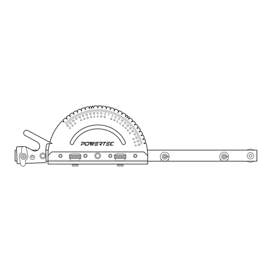
Precision Miter Gauge System
QUESTION...
1•847•780•6120
WARNING
For your own safety, read the machine's instruction manual before
using any accessory. Failure to heed these warnings may result in
serious personal injury and damage to the tool and the accessory.
• Before using the precision miter gauge system, read and follow
all of the provided instructions and safety information.
• Always keep hands clear of the blade, cutter, sanding disc/belt.
• Before making adjustments to the precision miter gauge
system, turn off the power, allow the blade, cutter or sanding
disc/belt to come to a complete stop and unplug the machine.
• Always make sure the handle and lock knob are tight
before using.
• Before turning on the power after adjustments, verify safe
clearance between the protractor and blade, cutter or sanding
disc/belt.
UNPACKING
Refer to Figure 1
Check for shipping damage. Check immediately whether all parts
and accessories are included.
ITEM DESCRIPTION
A
71142 Deluxe Miter Gauge with 27 angles
B
71488 Multi T-Track Fence with Laser Measure
(Right to Left)
C
71367 3" Fence Flip Stop with 5/16" T-Bolt and
instructions
D
Extra Expansion Discs
(Place in a safe place for future use)
E
Handle
F
Washer
G
3 mm Hex Wrench
H
2.5 mm Hex Wrench
Figure 1
B
H
G
D
A
TOOLS NEEDED
No additional tools are needed for assembly.
QTY
1
1
1
4
1
1
1
1
E
F
C
WARNING
Risk of accidental starting and serious personal injury. Unplug the
machine before attaching the precision miter gauge system.
ASSEMBLY
Refer to Figure 2, 3
1.
Loosen the small lock knob and rotate the miter head to move
the index lever from the shipping notch into the 0° position.
Figure 2
Indexing Lever
Lock Knob
3.
Place washer onto handle threads and thread the handle onto
the guide bar.
4.
Tighten handle and small lock knob.
Figure 3
Handle
ADJUST MITER GAUGE TO MITER SLOT
Refer to Figure 4, 5, 6
1.
Use a square to verify the miter bar is perpendicular to the
miter gauge face. The miter gauge is preset at the factory.
If not square or requires resetting, see Setting the Gauge
to 90°.
Figure 4
Miter
Gauge
Face
Miter Bar
NOTE: The notches are laser cut and are accurate to each
other. Once the miter gauge face is square to the bar, no other
adjustments are required. If by chance the workpiece is not
square, use a square to square the miter gauge face directly to
the blade or follow the instructions supplied with the machine to
square the machine's miter slot to the blade.
Model No. 71391
Miter Head
Lock Knob
Indexing Lever shown in
the 0° position
Miter Head
Square
19-0416
Advertisement

Related Manuals for PowerTec 71391

Summary of Contents for PowerTec 71391
- Page 1 INSTRUCTION SHEET Model No. 71391 WARNING Precision Miter Gauge System Risk of accidental starting and serious personal injury. Unplug the machine before attaching the precision miter gauge system. QUESTION... ASSEMBLY 1•847•780•6120 Refer to Figure 2, 3 Loosen the small lock knob and rotate the miter head to move the index lever from the shipping notch into the 0°...
- Page 2 SETTING THE GAUGE TO 90° If the tool is equipped with a T-slotted miter slot, use the included 2.5 mm hex wrench to ensure the screw holding Refer to Figure 8 the miter bar plate is tight. If the tool is not equipped with a T-slotted miter slot, remove the plate.
Need help?
Do you have a question about the 71391 and is the answer not in the manual?
Questions and answers