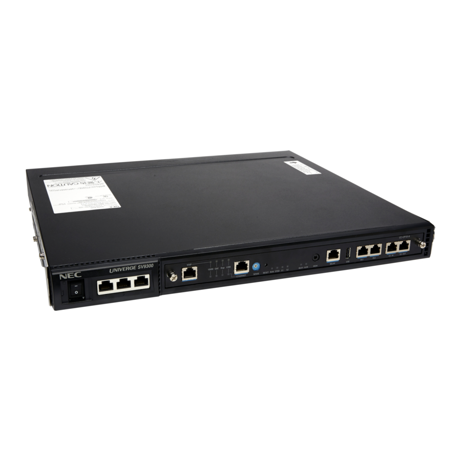
NEC UNIVERGE SV9300 System Maintenance Manual
Hide thumbs
Also See for UNIVERGE SV9300:
- Networking manual (364 pages) ,
- User manual (141 pages) ,
- Programming manual (47 pages)
Table of Contents
Advertisement
Quick Links
Advertisement
Table of Contents
Troubleshooting

Related Manuals for NEC UNIVERGE SV9300


Summary of Contents for NEC UNIVERGE SV9300
- Page 1 System Maintenance Manual NWA-088655-001 ISSUE 6.0...
- Page 2 NEC Platforms reserves the right to change the specifications, func- tions,or features, at any time, without notice. NEC Platforms has prepared this document for use by its employees and customers. The information contained herein is the property of NEC Platforms and shall not be reproduced without prior written approval from NEC Platforms.
-
Page 3: Table Of Contents
TABLE OF CONTENTS INTRODUCTION PURPOSE ........................ OUTLINE OF THIS MANUAL ................... TERMS IN THIS MANUAL ..................PBX System Designation ....................Attendant Console Name ....................Paging Adapter Name ..................... Terminal Name ........................ REFERENCE MANUAL ................... PRECAUTIONS ......................System Data Backup ....................... Chapter 1 MAINTENANCE SERVICES HOW TO READ THIS CHAPTER ................ - Page 4 BATTERY REPLACEMENT ..................1-31 FAULT REPORT SCHEDULING ................1-32 General Description ......................1-32 Service Conditions ......................1-32 Programming Procedure ....................1-33 Operating Procedure ....................... 1-34 ONLINE MP-FP COMMAND OUTPUT ..............1-35 General Description ......................1-35 Service Conditions ......................1-35 Overall Conditions ....................... 1-35 Conditions for Realtime Mode ..................
- Page 5 Programming Procedure ....................1-93 Operating Procedure ....................... 1-97 SYSTEM STATUS DISPLAY ................... 1-98 General Description ......................1-98 Service Conditions ......................1-98 Operating Procedure ....................... 1-105 Chapter 2 TROUBLESHOOTING PRECAUTIONS ......................Grounding Requirements ....................Static Electricity Guard ....................Turning Power ON ......................Turning Power OFF ......................
- Page 6 THIS PAGE LEFT BLANK INTENTIONALLY.
-
Page 7: Introduction
INTRODUCTION PURPOSE INTRODUCTION PURPOSE This manual explains the maintenance services provided with the SV9300, and the recommended trouble- shooting procedure when a fault has occurred, for maintenance personnel of this system. NOTE: As for the parts described as [9300V3 STEP2 software required] in this manual support 9300V3 STEP2 (SC 4351 LYRA BSC PROG V3.2.0) software or later. -
Page 8: Outline Of This Manual
INTRODUCTION OUTLINE OF THIS MANUAL OUTLINE OF THIS MANUAL This manual consists of two chapters. The following paragraphs summarize Chapters 1 and 2. CHAPTER 1 MAINTENANCE SERVICES This chapter describes the general description, service conditions, programming and operating procedure of the maintenance services. CHAPTER 2 TROUBLESHOOTING This chapter describes the precautions before troubleshooting, and the troubleshoot- ing procedure flow chart. -
Page 9: Terms In This Manual
PBX System Designation PBX system is designated as “PBX” or “system” usually. When we must draw a clear line between the PBX systems, they are designated as follows. SV9300: UNIVERGE SV9300 Attendant Console Name Attendant Console is usually designated as “Attendant Console”. - Page 10 INTRODUCTION TERMS IN THIS MANUAL In this manual, the following terminals are designated as each common term usually unless the type of terminal need to be identified in particular. COMMON TERMS TERMINAL NAMES term term Multiline Digital Multiline Terminal 85 (Series i) Terminal DT500 Series DT510...
-
Page 11: Reference Manual
INTRODUCTION REFERENCE MANUAL REFERENCE MANUAL During maintenance and troubleshooting, also refer to the manuals below: Command Manual: Contains the Customer Administration Terminal (CAT) operation, command functions and data re- quired for programming the system. PC Programming Manual: Contains the functional description and the installation procedure for the PCPro. System Hardware Manual: Contains the installation procedure for the PBX system and the hardware installation procedure for the SV9300. -
Page 12: Precautions
INTRODUCTION PRECAUTIONS PRECAUTIONS System Data Backup CAUTION • If you operate as follows without system data backup after system data setting or service memory setting (registration of the features such as “Call Forwarding” and “Speed Calling [Speed Dialing]” from a station), the data that has been set is invalid. You must execute the system data backup before the following operations. -
Page 13: Chapter 1 Maintenance Services
UNIVERGE SV9300 System Maintenance Manual MAINTENANCE SERVICES Chapter This chapter describes the general description, service conditions, programming and operating procedure of the maintenance services. -
Page 14: How To Read This Chapter
Chapter 1 MAINTENANCE SERVICES HOW TO READ THIS CHAPTER HOW TO READ THIS CHAPTER In the programming procedure, the meaning of (1), (2) and marking are as follows: (1): 1st Data (2): 2nd Data : Default With the system data clear command (CM00, CM01), the data with this marking is automatically assigned for each command. -
Page 15: Fault Message
Chapter 1 MAINTENANCE SERVICES FAULT MESSAGE FAULT MESSAGE General Description Fault Message This feature stores fault information into the Fault Store Memory, and displays the fault information on the PCPro or the Customer Administration Terminal (CAT). For CAT operation, refer to the Command Man- ual. -
Page 16: Service Conditions
Chapter 1 MAINTENANCE SERVICES FAULT MESSAGE Item Description Fault Display Number field Displays the unique number assigned to the fault infor- Area mation. Occurrence Date Displays the date and time at which the fault occurred. and Time field Error Type field Displays the number of the fault type. -
Page 17: Programming Procedure
Chapter 1 MAINTENANCE SERVICES FAULT MESSAGE Programming Procedure Fault Message To set the fault information storage from the PCPro by Command Operation: DESCRIPTION DATA START CM08 Enable the fault information storage feature. 1 : To store CMEA Assign which kind of fault information is •... - Page 18 Chapter 1 MAINTENANCE SERVICES FAULT MESSAGE DESCRIPTION DATA CMEA 1ST DATA 2ND DATA DATA MEANING DATA MEANING Terminal Disconnected External Alarm Kind 0: Fault Memory store/No output of SMDR output buffer (SRAM) exceeded 80 External Alarm 1: Fault Memory store/External Alarm is SMDR output buffer (SRAM) overflow MN alarm 2: Fault Memory store/External Alarm is...
- Page 19 Chapter 1 MAINTENANCE SERVICES FAULT MESSAGE DESCRIPTION DATA CMEA 1ST DATA 2ND DATA DATA MEANING DATA MEANING NOTE 10 Web server failure External Alarm Kind 0: No Fault Memory store/No output of Malicious Call List Overflow External Alarm [9300V3 software required] 1: Fault Memory store/External Alarm is MN alarm 2: Fault Memory store/External Alarm is...
- Page 20 Chapter 1 MAINTENANCE SERVICES FAULT MESSAGE DESCRIPTION DATA CMEA 1ST DATA 2ND DATA DATA MEANING DATA MEANING Lack of Highway Channel for data com- External Alarm Kind munication 0: Fault Memory store/No output of External Alarm 1: Fault Memory store/External Alarm is MN alarm 2: Fault Memory store/External Alarm is MJ alarm...
- Page 21 Chapter 1 MAINTENANCE SERVICES FAULT MESSAGE DESCRIPTION DATA CMEA 1ST DATA 2ND DATA DATA MEANING DATA MEANING NOTE 13 Remote Unit failure External Alarm Kind 0: No Fault Memory store/No output of External Alarm 1: Fault Memory store/External Alarm is MN alarm 2: Fault Memory store/External Alarm is MJ alarm...
- Page 22 Chapter 1 MAINTENANCE SERVICES FAULT MESSAGE DESCRIPTION DATA CMEA 1ST DATA 2ND DATA DATA MEANING DATA MEANING VoIPDB failure External Alarm Kind 0: No Fault Memory store/No output of VoIPDB notification External Alarm CPU failure 1: Fault Memory store/External Alarm is [9300V6 software required] MN alarm 2: Fault Memory store/External Alarm is...
- Page 23 Chapter 1 MAINTENANCE SERVICES FAULT MESSAGE DESCRIPTION DATA CMEA 1ST DATA 2ND DATA DATA MEANING DATA MEANING Fault Kind: Restoration ISDN D-channel link connection returned External Alarm Kind to normal condition 0: Fault Memory store/No output of External Alarm CCT link connection returned to normal 1: Fault Memory store/External Alarm is condition NOTE 15...
- Page 24 Chapter 1 MAINTENANCE SERVICES FAULT MESSAGE DESCRIPTION DATA CMEA 1ST DATA 2ND DATA DATA MEANING DATA MEANING DTI line returned to normal condition External Alarm Kind 0: Fault Memory store/No output of Blade returned to normal condition External Alarm Communication error restoration between 1: Fault Memory store/External Alarm is active CPU and stand by CPU MN alarm...
- Page 25 Chapter 1 MAINTENANCE SERVICES FAULT MESSAGE DESCRIPTION DATA CMEA 1ST DATA 2ND DATA DATA MEANING DATA MEANING Login lock returned to normal condition External Alarm Kind [9300V7 software required] 0: No Fault Memory store/No output of External Alarm Scam Call detection returned to normal 1: Fault Memory store/External Alarm is condition MN alarm...
- Page 26 Chapter 1 MAINTENANCE SERVICES FAULT MESSAGE NOTE 1: Even if the external alarm is set as MN or MJ alarm for system reset (1st data=01), no alarm is output in the case of Power On, Reset key operated, reset from the PCPro/CAT, and reset by CPU SENSE switch selection.
- Page 27 Chapter 1 MAINTENANCE SERVICES FAULT MESSAGE NOTE 8: This data is effective when the 2nd data of CMEA Y=2>125 is set to 0 (No Fault Memory store/No output of External Alarm). NOTE 9: Register the following failures with their detailed information as below. •...
- Page 28 Chapter 1 MAINTENANCE SERVICES FAULT MESSAGE NOTE 19: It takes up to two seconds to detect a status change of LAN cable connection. Therefore, a momentary breakdown of LAN cable may not be detected and the fault information may not be registered.
- Page 29 Chapter 1 MAINTENANCE SERVICES FAULT MESSAGE To clear the MJ/MN alarm by external key: START DESCRIPTION DATA CM05 Assign a Unit and Slot number to the DLC • blade. XX ZZ XX: 01-50: Unit No. BLADE RESET ZZ : 01-18: Slot No. 10: DLC blade NOTE: When the PGD(2)-U10 ADP is...
-
Page 30: Operating Procedure
Chapter 1 MAINTENANCE SERVICES FAULT MESSAGE DESCRIPTION DATA CM13 Allow the accommodation of PGD(2)-U10 • Y=63 ADP. X-XXXXXXXX: Station No. 0 : To accommodate BLADE RESET 1 : Not accommodated NOTE1: Set this data only for a Base Port No. (Circuit No. 01) of DLC blade. NOTE2: Whether the following equipments can be accommodated to the same DLC blade or not are depended on this data. -
Page 31: Station Line Status Display
Chapter 1 MAINTENANCE SERVICES STATION LINE STATUS DISPLAY STATION LINE STATUS DISPLAY General Description This feature displays the line status for a Single Line Telephone or a Multiline Terminal using the CAT or the PCPro. Service Conditions This feature is not available when the system is off-line. Programming Procedure No programming is required. - Page 32 Chapter 1 MAINTENANCE SERVICES STATION LINE STATUS DISPLAY (c) Hardware Test See “Status of Single Line Telephone/Multiline Terminal” below. Status of Single Line Telephone/Multiline Terminal STATUS OF STATUS OF STATUS OF INDICATION DIGITAL MULTILINE SINGLE LINE TEL. IP STATION TERMINAL Normal operation of Terminal is not connected Terminal is not connected...
-
Page 33: Battery Release Control
Chapter 1 MAINTENANCE SERVICES BATTERY RELEASE CONTROL BATTERY RELEASE CONTROL General Description When the AC power is cut off intentionally (such as maintenance for the building), this feature can dis- connect the batteries from the SV9300, using the PCPro or the CAT, and prevent an excessive discharge of the battery. -
Page 34: Operating Procedure
Chapter 1 MAINTENANCE SERVICES BATTERY RELEASE CONTROL Operating Procedure Operation from PCPro The battery release can be controlled by the System Data mode of PCPro. For details, refer to the PC Programming Manual. Command Operation from CAT • To disconnect the battery: COMMAND= EC0>... -
Page 35: Diagnostics
Chapter 1 MAINTENANCE SERVICES DIAGNOSTICS DIAGNOSTICS General Description To assist maintenance personnel, this feature provides diagnostic capabilities such as fault code genera- tion, device status information and alarm information recording, which can be accessed from the PCPro or the CAT. Service Conditions The following station status information can be displayed on the PCPro or the CAT by direct command:... -
Page 36: Programming Procedure
Chapter 1 MAINTENANCE SERVICES DIAGNOSTICS The following information is stored and can be displayed on the PCPro or the CAT using a memory dump command in hexadecimal format: • Program address where an endless loop has occurred • Last reset time for main program •... - Page 37 Chapter 1 MAINTENANCE SERVICES DIAGNOSTICS Station Status Information STATUS CODE DESCRIPTION Idle In Line Lockout mode Dialing to a PBR Dialing to a trunk Dialing to a PBR (After consultation hold a station) Dialing to a PBR (After consultation hold a trunk) Dialing to a trunk (After consultation hold a station) Dialing to a trunk (After consultation hold a trunk) Dialing to a PBR (After consultation hold 3 party Conference Trunk)
- Page 38 Chapter 1 MAINTENANCE SERVICES DIAGNOSTICS Station Status Information STATUS CODE DESCRIPTION Holding Voice Call to a Multiline Terminal Voice Call from a Station In Station to Trunk connection Three-Way Calling with a station and a trunk In a CAT mode (For Multiline Terminal) In a UCD Queue In a UCD Queue after holding a station In a UCD Queue after holding a trunk...
- Page 39 Chapter 1 MAINTENANCE SERVICES DIAGNOSTICS • Trunk Status Information: COMMAND= F50> DXXX : XXXXXXXX XXXXXXXXX 0 + DXXX (Trunk No.) *c *d *e *f *g XXXXXXXXXXXXXXXXXXXXXXX *h *i *j *k *l *m *n *o *p *q *r *a : Trunk No. *b : Designated Address *c-*r: Status Code of the designated Address 0-15 For the meaning of status code, see “Trunk Status Information”.
- Page 40 Chapter 1 MAINTENANCE SERVICES DIAGNOSTICS Trunk Status Information STATUS CODE DESCRIPTION Incoming queue to Attendant Console Attendant Camp On In a trunk to station connection Dialing In (Tie Line) In a tandem connection Hold by Exclusive/Nonexclusive Hold TAS in progress Incoming queue to UCD Three-Way Calling with a station and two trunks In Ringback Tone/Busy Tone connection (Tie Line)
- Page 41 Chapter 1 MAINTENANCE SERVICES DIAGNOSTICS • Alarm Information: COMMAND= F53> XXXX : XXXXXXXX XXXXXXXXX XXXX (Memory Dump Data) XXXXXXXXXXXXXXXXXXXXXX *a: Memory Dump Data *b: Designated Address *c: See “Alarm Information”. Page 1-30 1-29...
- Page 42 Chapter 1 MAINTENANCE SERVICES DIAGNOSTICS Alarm Information MEMORY DUMP DATA ALARM INFORMATION 0000 Last Reset Time for Central Processing Unit (CPU) YYYY MM DD HH MM SS Second (00-59) Minute (00-59) Hour (00-23) Date (01-31) Month (01-12) Year (2014-2999) 0001 Reason for System Reset 00 : Power on No fault...
-
Page 43: Battery Replacement
Chapter 1 MAINTENANCE SERVICES BATTERY REPLACEMENT BATTERY REPLACEMENT The interval of battery replacement depends on the ambient temperature. The following caution label shows battery replacement interval and attached to the CPU chassis. When you set up the battery for the first time, you must keep the record of the installation date and the replacement date. -
Page 44: Fault Report Scheduling
Chapter 1 MAINTENANCE SERVICES FAULT REPORT SCHEDULING FAULT REPORT SCHEDULING General Description This feature allows the system to register pre-determined date for periodic maintenance in advance and notify the information on the day by the Multiline Terminal function key lamp. SV9300 Indicate the lamp on the scheduled date... -
Page 45: Programming Procedure
Chapter 1 MAINTENANCE SERVICES FAULT REPORT SCHEDULING Programming Procedure To set a periodic maintenance reminder, do the following programming. START DESCRIPTION DATA CM43 Assign the date and time setting for periodic • maintenance. 00-07 Periodic maintenance YYYY MM DD HH YYYY: 2014-2099 (Year) : 01-12 (Month) : 01-31 (Date) -
Page 46: Operating Procedure
Chapter 1 MAINTENANCE SERVICES FAULT REPORT SCHEDULING Operating Procedure Operation from PCPro The alarm display can be cleared by the System Data mode of PCPro. For details, refer to the PC Programming Manual. Command Operation from CAT • To clear the alarm display: COMMAND= EA1>... -
Page 47: Online Mp-Fp Command Output
Chapter 1 MAINTENANCE SERVICES ONLINE MP-FP COMMAND OUTPUT ONLINE MP-FP COMMAND OUTPUT General Description This feature allows the system to collect MP-FP commands which are sent/received during an operation and output them to PCPro. There are two modes for the MP-FP command output. •... -
Page 48: Conditions For Realtime Mode
Chapter 1 MAINTENANCE SERVICES ONLINE MP-FP COMMAND OUTPUT Conditions for Realtime Mode When a system reset is executed while the system is operating, the setting of MP-FP command output (CMF6 Y=2>03) is set to default (second data 3) and the output is stopped. If you enter CCC by CMF6 Y=2>03, all settings assigned by CMF6 Y=2>00/01/02/03 are initialized. -
Page 49: Conditions For Storage Mode
Chapter 1 MAINTENANCE SERVICES ONLINE MP-FP COMMAND OUTPUT Conditions for Storage Mode <Conditions for Storing MP-FP Command> The Storage mode can store about 9,000 calls’ MP-FP commands into the buffer in a CPU blade (SDRAM: 64M bytes). As for the storage methods of MP-FP commands, you can select the Overwrite method and the Fixing method (set by CMF6 Y=2>91). - Page 50 Chapter 1 MAINTENANCE SERVICES ONLINE MP-FP COMMAND OUTPUT Start of the MP-FP command’ storage and change of the storage method is available only in the “Stopped state” (CMF6 Y=2>90: 0) and the “State of ending output” (CMF6 Y=2>93: 3). By reading the oldest/latest time of the stored MP-FP commands by CMF6 Y=2>92, you can check the range of stored MP-FP commands in the buffer which is under the storage process (the displayed time is the time of system clock at the time that the MP-FP commands are stored in the buffer.
- Page 51 Chapter 1 MAINTENANCE SERVICES ONLINE MP-FP COMMAND OUTPUT (c) “Ending output execution” (CMF6 Y=2>93: 3) • The contents in the buffer are retained even if the MP-FP command output is ended. When the output of all MP-FP commands in the buffer is completed, “Ending output execution” (CMF6 Y=2>93: 3) is automatically set.
-
Page 52: Programming Procedure
Chapter 1 MAINTENANCE SERVICES ONLINE MP-FP COMMAND OUTPUT Programming Procedure To output MP-FP commands by the realtime mode, do the following programming. (a) To set the port for MP-FP command output: DESCRIPTION DATA START CM40 Set the RS/LAN port for MP-FP command •... - Page 53 Chapter 1 MAINTENANCE SERVICES ONLINE MP-FP COMMAND OUTPUT DESCRIPTION DATA CMF6 Assign the Slot number to be output (for real- • time mode). 02: Slot No. to be output (for realtime mode) NOTE: To the second data, assign the value XXX: Slot No.
- Page 54 Chapter 1 MAINTENANCE SERVICES ONLINE MP-FP COMMAND OUTPUT To output MP-FP commands by the storage mode, do the following programming. (a) To set the port for MP-FP command output: START DESCRIPTION DATA CM40 Set the RS/LAN port for MP-FP command •...
- Page 55 Chapter 1 MAINTENANCE SERVICES ONLINE MP-FP COMMAND OUTPUT (d) To display the oldest time/latest time of stored data in storage buffer: START DESCRIPTION DATA CMF6 Display the oldest time/latest time of stored • data in storage buffer (for storage mode) (dis- play only).
-
Page 56: Operating Procedure
Chapter 1 MAINTENANCE SERVICES ONLINE MP-FP COMMAND OUTPUT Operating Procedure 1. MP-FP command output by the Realtime mode For output via RS232C: <Conditions> • The CPU blade of each Unit shall be set to the on-line mode by the SENSE switch. Page 1-40 •... - Page 57 Chapter 1 MAINTENANCE SERVICES ONLINE MP-FP COMMAND OUTPUT STEP3: Take one of these actions by PCPro and display the [Trace Information] screen. • Click the [Trace] by the submenu on the Command Mode. • Click the [System] > [Maintenance] > [Trace] in this order. * As for the details of the Trace feature, refer to the on-line help of PCPro or PC Program- ming Manual.
- Page 58 Chapter 1 MAINTENANCE SERVICES ONLINE MP-FP COMMAND OUTPUT STEP4: Take one of these actions by PCPro and display the [Trace Information] screen. • Click the [Trace] by the submenu on the Command Mode. • Click the [System] > [Maintenance] > [Trace] in this order. * As for the details of the Trace feature, refer to the on-line help of PCPro or PC Program- ming Manual.
-
Page 59: Voip Log Collection
Chapter 1 MAINTENANCE SERVICES VoIP LOG COLLECTION VoIP LOG COLLECTION General Description By collecting the fault logs or call logs and outputting them, you can know the causes when faults or error occur in the SV9300 (Fault Log/Call Log Collection). Also, by collecting and storing the call logs between locations, you can verify and analyze the voice quality based on the statistical result (VoIP Packet Statistics). - Page 60 Chapter 1 MAINTENANCE SERVICES VoIP LOG COLLECTION Call Log Collection You can collect the call logs and output them to the RS port of CPU by system data setting. You can analyze communication conditions of the IP network. Also, collected call log information can be notified to the SNMP manager by using SNMP Trap. [9300V4 software required] Call Log Collection SNMP Manager...
- Page 61 Chapter 1 MAINTENANCE SERVICES VoIP LOG COLLECTION VoIP Packet Statistics [9300V4 software required] This feature collects the call logs notified by the Call Log Collection feature between locations on sending/receiving sides of VoIP packets on hourly basis and stores the statistical results from minimum of 1 hour to about one month on SV9300.
-
Page 62: Service Conditions
Chapter 1 MAINTENANCE SERVICES VoIP LOG COLLECTION Service Conditions General conditions • Terminals/blades and available firmware versions that enable to collect fault logs/call logs/VoIP Packet Statistics are as follows. : Available : Not available Availability 9300V4 software or 9300V3 software or later before Firmware... - Page 63 Chapter 1 MAINTENANCE SERVICES VoIP LOG COLLECTION - ITR-16D-2 (BK/WH) TEL (Available when firmware of ITR-16D-3 (BK/WH) TEL is installed) - ITR-8D-2A (BK/WH) TEL (Available when firmware of ITR-8D-3A (BK/WH) TEL is installed) - ITR-16D-2A (BK/WH) TEL (Available when firmware of ITR-16D-3A (BK/WH) TEL is installed) - ITR-8D-2U (BK/WH) TEL (Available when firmware of ITR-8D-3 (BK/WH) TEL is installed)
- Page 64 Chapter 1 MAINTENANCE SERVICES VoIP LOG COLLECTION • The output format of fault logs is as follows. STN31100 14/04/30 12:48:19 DATA=1:RESET CAUSE 1=06440755 14/04/25 17:38:35 2=06440755 14/04/25 18:23:19 3=06440755 14/04/25 18:26:06 4=06440755 14/04/28 10:34:17 5=06440755 14/04/28 14:50:03 6=06440755 14/04/28 16:23:48 7=06440755 14/04/28 20:26:53 8=06440755 14/04/30 12:48:03 DATA=2:CONTROL PACKET COUNTER (PROTOCOL=2)
- Page 65 Chapter 1 MAINTENANCE SERVICES VoIP LOG COLLECTION 4. Cause for reset: AABBCCDD (AA=major division, BB/CC/DD=not used) NOTE 2 term term <D 85 (Series i) (IP Bundled Type/IP Adapter Type)/D SP30/DT700/DT800/DT900 Series> NOTE 6 MEANING Self Reset: Before the registration/Before DRS01 (required a default setting) Self Reset: During the registration/Before DRS03 (confirmed a reply of signal pass setting) Self Reset: After the registration/During a default setting...
- Page 66 Chapter 1 MAINTENANCE SERVICES VoIP LOG COLLECTION 7. Number of sending/received control packets: XXXXXXXX NOTE 3 • For PROTOCOL=1 (iLP-PM) 1: Total number of sending control packets 2: Number of re-sending control packets 3: NG number of re-sending control packets 4: Total number of received control packets 5: Total number of received error packets 6: Number of error sequences...
- Page 67 Chapter 1 MAINTENANCE SERVICES VoIP LOG COLLECTION • For PROTOCOL=4 (UDP/H.245) 1 : Total number of sending packets 2 : Number of master mode UDP sending packets 3 : Number of master mode UDP re-sending packets 4 : Number of slave mode UDP sending packets 5 : Number of slave mode UDP re-sending packets 6 : Number of H.245 packets sending 7 : Total number of received packets...
- Page 68 Chapter 1 MAINTENANCE SERVICES VoIP LOG COLLECTION <Y=DRS number: 1 to 4> 1: Primary 2: Secondary 3: Tertiary 4: Fourth 9. Fault log reading timeout display NOTE 5 NOTE 1: For the fault logs collection after the VoIPDB reset execution, the least channel number of the VoIPDB is displayed.
- Page 69 Chapter 1 MAINTENANCE SERVICES VoIP LOG COLLECTION • When you cannot output the call logs to the RS port of the CPU due to disconnection, etc., the CPU blade can be collected up to 256 logs. If the logs exceed 256 logs, you can specify whether to overwrite them or not by system data setting (CMEA Y=6>02).
- Page 70 Chapter 1 MAINTENANCE SERVICES VoIP LOG COLLECTION • Conditions for call log collection of SIP trunk (a) Call log of SIP trunk is notified from SIP trunk to CPU blade when sending/receiving of RTP packet are completed. (b) For the number of RTP packets sent in call log, the number of transmissions of SIP trunk is saved.
- Page 71 Chapter 1 MAINTENANCE SERVICES VoIP LOG COLLECTION • Even if one call log is not notified during an hour between locations for a call log collection, SV9300 stores each parameter as “0”. • VoIP Packet Statistics immediately starts the call log collection after the location for a call log collection is set.
- Page 72 Chapter 1 MAINTENANCE SERVICES VoIP LOG COLLECTION • When a system changeover occurred on the Dual CPU system, the call log collection after the system changeover is restarted from the state of point when the data is automatically or manually copied just before the system changeover.
- Page 73 Chapter 1 MAINTENANCE SERVICES VoIP LOG COLLECTION Example 2 * The automatic (periodic) copy of the Dual CPU system shall be performed from 15 to 18 minutes per hour by following the default setting. During collecting the VoIP Packet Statistics on #0 ACT-CPU (during collecting to record 099) 09:15 Execute the automatic (periodic) copy.
- Page 74 Chapter 1 MAINTENANCE SERVICES VoIP LOG COLLECTION • The operations of this feature when executing the clear commands by the system data are as follows. : Available : Not available System Status System Data Operation of This Feature On-Line Off-Line ...
- Page 75 Chapter 1 MAINTENANCE SERVICES VoIP LOG COLLECTION Conditions of SNMP Trap Output [9300V4 software required] • By using SNMP Trap, Information collected by the Call Log Collection feature can automatically be notified to SNMP manager with SNMP V1 format. The table below shows the notified call log information and MIB object/ID.
- Page 76 Chapter 1 MAINTENANCE SERVICES VoIP LOG COLLECTION Access to Notified Call Log Information Object/ID Object ipsTermi- Call log information format of SNMP-Trap is as follows. nalStatsData/ 1.3.6.1.4.1.119. 2.3.76.3.6.1 (RTP Statistics Explanation of Screen Information: Call log SNMP TRAP when calling Output Trap) term term...
-
Page 77: Programming Procedure
Chapter 1 MAINTENANCE SERVICES VoIP LOG COLLECTION Programming Procedure To execute the fault log/call log collection: START DESCRIPTION DATA CM0B Provide the call log collection with the • Y=2XX (VOIP Port [2] + Unit No. [01-50]) VoIPDB. 0: To provide NOTE: When changing this data for VoIPDB accommodated in a Remote... - Page 78 Chapter 1 MAINTENANCE SERVICES VoIP LOG COLLECTION DESCRIPTION DATA CMEA Specify the output destination for the fault • logs/call logs. 00: Output destination of fault/call logs 2 : RS port of CPU NOTE: Set the output port for fault logs/call 3 : Not output logs by CM40 Y=00.
- Page 79 Chapter 1 MAINTENANCE SERVICES VoIP LOG COLLECTION DESCRIPTION DATA CM40 Specify the stop bit for the RS port. • Y=04 0: Unit01 Port1 NOTE: When using CPU RS-232C port for 1: Unit01 Port2 PCPro, set the default. 0 : 1-Stop bit 1 : 2-Stop bit Specify the DTR signal sent to terminal for the •...
- Page 80 Chapter 1 MAINTENANCE SERVICES VoIP LOG COLLECTION • To collect the fault logs manually, do the following programming. START DESCRIPTION DATA CMEA Specify the terminals/VoIPDB to collect fault • logs. 11: Specification of fault log collection ter- minal/VoIPDB NOTE: When reading this data, second data X-XXXXXXXX: IP Station No.
- Page 81 Chapter 1 MAINTENANCE SERVICES VoIP LOG COLLECTION DESCRIPTION DATA CM12 Assign the location number of the IP Station • Y=50 for remote connection. X-XXXXXXXX: Station No. 00-63 : Location No. 00-63 for Local Connection NONE : Location No. 00 CM8A Assign the location number of the group to •...
- Page 82 Chapter 1 MAINTENANCE SERVICES VoIP LOG COLLECTION • VoIP Packet Statistics can be displayed by the following system data. START DESCRIPTION DATA CMB6 Display the VoIP Packet Statistics. • Y=01 aabccc aa : 00-09: Location Combination Pattern b : 0/1: Location A/Location B ccc: 000-799: Record No.
- Page 83 Chapter 1 MAINTENANCE SERVICES VoIP LOG COLLECTION • To clear the stored data of VoIP Packet Statistics, do the following programming. START DESCRIPTION DATA CMB6 Clear the stored data of VoIP Packet Statistics. • Y=01 00-09: Location Combination Pattern No. NOTE: If the stored data is cleared, the both CCC: Location No.
-
Page 84: Qos Display On Ip Multiline Terminal
Chapter 1 MAINTENANCE SERVICES QoS DISPLAY ON IP MULTILINE TERMINAL QoS DISPLAY ON IP MULTILINE TERMINAL General Description This feature allows IP Multiline Terminal to display the Number of lost packets, CODEC type, and Pay- load size of IP Multiline Terminal communication on the LCD by pressing the function key. This feature also allows SIP Multiline Terminal to display the Number of lost packets, CODEC type, and Payload size of SIP Multiline Terminal communication on the LCD by pressing the HELP key continuously. -
Page 85: Service Conditions
Chapter 1 MAINTENANCE SERVICES QoS DISPLAY ON IP MULTILINE TERMINAL Service Conditions Number of lost packets, CODEC type, and Payload size are displayed with pressing the Function key that has been set during a communication. The displayed QoS information on the LCD is updated every 5 seconds. All information sent from the PBX is not displayed while the QoS information is displayed on the LCD. -
Page 86: Station Service Status Display
Chapter 1 MAINTENANCE SERVICES STATION SERVICE STATUS DISPLAY STATION SERVICE STATUS DISPLAY General Description This feature allows the system to readout the setting status of the service for each station. Service Conditions The services whose setting status can be readout by this feature are the features that are set to Single Line Telephone, Multiline Terminal, virtual station and built-in modem. -
Page 87: Programming Procedure
Chapter 1 MAINTENANCE SERVICES STATION SERVICE STATUS DISPLAY Programming Procedure Operation from PCPro A station service status for each station can be displayed by the System Data mode of PCPro. For details, refer to the PC Programming Manual. Command Operation from CAT •... - Page 88 Chapter 1 MAINTENANCE SERVICES STATION SERVICE STATUS DISPLAY Table A (Readout Service Status A for Each Station) DISPLAYED DISPLAY MEANING SERVICES CONTENT a: Terminal connection Terminal is connected (for Multiline Terminal only) status Terminal is not connected (for Multiline Terminal only) Readout Error _ (Underscore) Off-line status or Terminal is not available...
- Page 89 Chapter 1 MAINTENANCE SERVICES STATION SERVICE STATUS DISPLAY Table B (Readout Service Status B for Each Station) DISPLAYED DISPLAY MEANING FEATURES CONTENT i : Mobility access (Station Mobility access OFF/Dual Ringing OFF Access/Call Forward- Mobility access ON/Dual Ringing OFF ing)/Dual Ringing Mobility access OFF/Dual Ringing ON Mobility access ON/Dual Ringing ON _ (Underscore)
-
Page 90: Ping Command
Chapter 1 MAINTENANCE SERVICES PING COMMAND PING COMMAND General Description By executing a ping command from the PCPro or the Customer Administration Terminal (CAT), you can send a ping request to IP Station from the SV9300. This enables you to confirm whether the IP terminal is correctly connected/set or not. - Page 91 Chapter 1 MAINTENANCE SERVICES PING COMMAND You cannot execute the ping command from multiple PCPro/CAT terminals at once. If you do that, “WAIT, BUSY NOW” is displayed. Even if a LAN port on the CPU blade is being used for PCPro/OAI or any other terminals, you can execute the ping command.
- Page 92 Chapter 1 MAINTENANCE SERVICES PING COMMAND ICMP TYPE used in this feature is as follows. List of ICMP TYPE ICMP CLASSIFI- GENERAL DESCRIPTION MEANING TYPE CATION Reply Reply to the echo request by exe- • Ping reply (ping OK) cuting the ping command (echo reply) Reply Reply message resulting by the ping...
-
Page 93: General Description
Chapter 1 MAINTENANCE SERVICES PING COMMAND List of ICMP TYPE ICMP CLASSIFI- GENERAL DESCRIPTION MEANING TYPE CATION Reply Reply message resulting by the IP • IP header abnormal (error) header being abnormal or a required • Required options are unknown. option is not effective. -
Page 94: Operating Procedure
Chapter 1 MAINTENANCE SERVICES PING COMMAND Operating Procedure By executing the command (CMFA Y=2001) from PCPro or CAT, and assign the IP address of the terminal you want to send a ping request. Then confirm an reply message resulting by executing the ping command. Example: Assign “192.168.1.3”... -
Page 95: Maintenance Report
Chapter 1 MAINTENANCE SERVICES MAINTENANCE REPORT MAINTENANCE REPORT General Description This feature can create the maintenance report (Excel file) and output the information of maintenance work (such as inspection check and system data changes using PCPro) performed by maintenance personnel at the customer’s environment. -
Page 96: Time Synchronization With Sntp
Chapter 1 MAINTENANCE SERVICES TIME SYNCHRONIZATION WITH SNTP TIME SYNCHRONIZATION WITH SNTP General Description Simple Network Time Protocol (SNTP) is a standard protocol that can synchronize time from the SNTP server over the network. The SV9300 can support SNTP standard defined in IETF RFC 2030. This feature provides automatic error correction for the SV9300 system clock from the SNTP server over the network. -
Page 97: Service Conditions
Chapter 1 MAINTENANCE SERVICES TIME SYNCHRONIZATION WITH SNTP Service Conditions To run this feature, proper IP addresses must be assigned to VoIPDB. This feature is available for Main Unit (Unit01) and Secondary Unit in Failover mode only. For Remote Unit in normal mode, SNTP control is not provided, and it is dependent on the Main Unit (Unit01) clock. -
Page 98: Programming Procedure
Chapter 1 MAINTENANCE SERVICES TIME SYNCHRONIZATION WITH SNTP Condition for the concern of other services The result of time correction, the following services may be affected. Set the query time to SNTP at the low frequency time to make the effect into the minimum. 1. - Page 99 Chapter 1 MAINTENANCE SERVICES TIME SYNCHRONIZATION WITH SNTP DESCRIPTION DATA CM02 Set the time difference between the System Clock and UTC. Time Zone (See the table below) NONE : No Time Zone +15 minute increments -15 minute increments 2nd Data Time Zone 2nd Data Time Zone...
- Page 100 Chapter 1 MAINTENANCE SERVICES TIME SYNCHRONIZATION WITH SNTP To confirm SNTP query: START DESCRIPTION DATA CMFC Read the latest SNTP Result. • Y=01 (Unit01) 0026 : Succeed : Internal Error (Undefined) : No Response (Time out) : Internal Error (API arguments error in VoIPDB) : Internal Error (Socket error in VoIPDB)
-
Page 101: Operating Procedure
Chapter 1 MAINTENANCE SERVICES TIME SYNCHRONIZATION WITH SNTP Operating Procedure No operating is required. 1-89... -
Page 102: Security Function For Remote Maintenance
Chapter 1 MAINTENANCE SERVICES SECURITY FUNCTION FOR REMOTE MAINTENANCE SECURITY FUNCTION FOR REMOTE MAINTENANCE General Description This feature can be enhanced the security of remote maintenance by enabling the operation from only the permitted maintenance person, when operating remote access to built-in modem. illegal access User’s environment from PCPro... -
Page 103: Service Conditions
Chapter 1 MAINTENANCE SERVICES SECURITY FUNCTION FOR REMOTE MAINTENANCE Restriction of the remote access by user operation The key of remote maintenance is set to Multiline Terminal in advance. At the starting of maintenance, the key is pushing down to permit the temporary remote access. After a definite period of time, the setting of key returns automatically to restriction remote access. - Page 104 Chapter 1 MAINTENANCE SERVICES SECURITY FUNCTION FOR REMOTE MAINTENANCE Conditions for Manual Operation by Multiline Terminal This feature is applicable for the following terminals. term DT300/DT400/DT500/DT700/DT800/DT900 Series, D 85 (Series i) and MH240 Whether to provide this feature can be specified by CM40 Y=10>2. While remote access is being restricted by this feature, all remote access from C.O.
-
Page 105: Programming Procedure
Chapter 1 MAINTENANCE SERVICES SECURITY FUNCTION FOR REMOTE MAINTENANCE Conditions for Illegal Access Situation Illegal access situation can be confirmed by reading out of peg count with predetermined number assigned by CMB0 Y=0>099, under remote maintenance restriction by calling party number authentication or pushing down the key of remote maintenance. - Page 106 Chapter 1 MAINTENANCE SERVICES SECURITY FUNCTION FOR REMOTE MAINTENANCE To restrict remote access by calling party number authentication: START DESCRIPTION DATA CM35 Restrict the Remote Maintenance via built-in • Y=319 modem. 00-63: Trunk Route No. 0 : Restricted by Calling Party No. NOTE1: Set the second data to 0 (Restricted 1 : All restricted...
- Page 107 Chapter 1 MAINTENANCE SERVICES SECURITY FUNCTION FOR REMOTE MAINTENANCE To restrict remote access by user operation: START DESCRIPTION DATA CM40 Restrict the Remote Maintenance by user oper- • Y=10 ation via built-in modem. 0: Available CM41 Assign the remote maintenance permission •...
- Page 108 Chapter 1 MAINTENANCE SERVICES SECURITY FUNCTION FOR REMOTE MAINTENANCE To confirm illegal access: • To count the restricted number of remote maintenance via built-in modem, do the following programming. START DESCRIPTION DATA CMB0 Count the restricted number of remote mainte- •...
-
Page 109: Operating Procedure
Chapter 1 MAINTENANCE SERVICES SECURITY FUNCTION FOR REMOTE MAINTENANCE Operating Procedure To restrict remote access by calling party number authentication: No operation is required. To restrict remote access by user operation: a. Under remote maintenance restriction Pushing down the key of remote maintenance (assigned by CM90 Y=00: F1364). -
Page 110: System Status Display
Chapter 1 MAINTENANCE SERVICES SYSTEM STATUS DISPLAY SYSTEM STATUS DISPLAY [9300V3 STEP2 software required] General Description By command operations from CAT/PCPro, this feature allows the system to read out the operation status of the following hardware, lines and the presence of failures. Consequently, you can easily confirm the status of a system at that time. - Page 111 Chapter 1 MAINTENANCE SERVICES SYSTEM STATUS DISPLAY The following table shows the statuses of each hardware and line that can be confirmed. HARDWARE/ RELATED STATUS CONTENT LINE FAULT CODE Controlling Chassis Connection Status Confirm whether a communication 042, 052, 119, Status Display between CPU blade of Unit01 and 11A, 11B...
- Page 112 Chapter 1 MAINTENANCE SERVICES SYSTEM STATUS DISPLAY HARDWARE/ RELATED STATUS CONTENT LINE FAULT CODE Expansion Chassis Connection Status Confirm the connection of Expan- 112, 113, 114, Status Display sion Chassis. 115, 116 (CMF9 Y=10) *1 It takes up to four minutes to detect a status change.
- Page 113 Chapter 1 MAINTENANCE SERVICES SYSTEM STATUS DISPLAY HARDWARE/ RELATED STATUS CONTENT LINE FAULT CODE VoIPDB Status Mounting Status Confirm whether VoIPDB is Display mounted to a Controlling Chassis. (CMF9 Y=30) *1 To detect a status change, it takes one minute at VoIPDB startup or two minutes during VoIPDB operation.
- Page 114 Chapter 1 MAINTENANCE SERVICES SYSTEM STATUS DISPLAY HARDWARE/ RELATED STATUS CONTENT LINE FAULT CODE VoIPDB Status LAN Cable Con- When the Operation Status is “Nor- 12D, 12E Display nection Status mal operation”, confirm the LAN (CMF9 Y=30) cable connection of VOIP port of Unit01 and the secondary unit in a Failover Mode.
- Page 115 Chapter 1 MAINTENANCE SERVICES SYSTEM STATUS DISPLAY HARDWARE/ RELATED STATUS CONTENT LINE FAULT CODE Station/Trunk Line Link Confirm whether one or more fail- 021, 022, 031, Blade Status connection ures have occurred among ISDN D 032, 102, 103 Display NOTE channel/CCT link failure, Digital (CMF9 Y=40) Tie line failure and ISDN line fail-...
- Page 116 Chapter 1 MAINTENANCE SERVICES SYSTEM STATUS DISPLAY NOTE: Station/Trunk blades that can be confirmed the Line Link connection are as follows. (a) Blades which display the Line Link connection with Line 1 - Line 4. • Basic Rate (2B + D) Interface Trunk Blade (CM05 Y=0: 40). •...
-
Page 117: Operating Procedure
Chapter 1 MAINTENANCE SERVICES SYSTEM STATUS DISPLAY Operating Procedure Operation from PCPro With System Data Mode of PCPro, you can confirm the operation status of hardware/lines and the presence of failures at that time. For details, refer to the System Data Mode of PC Programming Manual. - Page 118 Chapter 1 MAINTENANCE SERVICES SYSTEM STATUS DISPLAY Controlling Chassis Status Display (CMF9 Y=00) Detailed Table DISPLAYED SERVICES DISPLAY CONTENT MEANING NOTE a: Connection Status Connected Disconnected b: Operation Status NOTE Normal mode Survival mode c: FAN Alarm Not detected Detected d: AC Input Failure Not detected Detected...
- Page 119 Chapter 1 MAINTENANCE SERVICES SYSTEM STATUS DISPLAY • To display Expansion Chassis status (CMF9 Y=10) COMMAND=_ F910 COMMAND=F910 F910> COMMAND=F910 F910>XXZ: a b c d e f g h (Unit No. + Expansion Chassis No.) XX : 01-50 (Unit No.01-50) a : Connection Status Z : 1-3 (Expansion Chassis 1 [Slot01-06]/ b : Operation Status...
- Page 120 Chapter 1 MAINTENANCE SERVICES SYSTEM STATUS DISPLAY Expansion Chassis Status Display (CMF9 Y=10) Detailed Table DISPLAYED SERVICES DISPLAY CONTENT MEANING a: Connection Status Connected Disconnected b: Operation Status Normal operation Operation stopped c: FAN Alarm Not detected Detected d: AC Input Failure Not detected Detected e: Power OFF Alarm...
- Page 121 Chapter 1 MAINTENANCE SERVICES SYSTEM STATUS DISPLAY • To display VoIPDB Status (CMF9 Y=30) COMMAND=_ F930 COMMAND=F930 F930> COMMAND=F930 F930>XXZ: a b c d e f g h (Unit No. + CPU kind) XX : 01-50 (Unit No.01-50) a : Mounting Status Z : 0/1 (Single CPU or ACT-CPU/ b : Operation Status STBY-CPU for Dual CPU)
- Page 122 Chapter 1 MAINTENANCE SERVICES SYSTEM STATUS DISPLAY VoIPDB Status Display (CMF9 Y=30) Detailed Table DISPLAYED SERVICES DISPLAY CONTENT MEANING a: Mounting Status Mounted Not mounted b: Operation Status Normal operation Operation stopped c: LAN Cable Connection Status Connected Disconnected d: Not used Always “-”...
- Page 123 Chapter 1 MAINTENANCE SERVICES SYSTEM STATUS DISPLAY • To display Station/Trunk Blade Status Display (CMF9 Y=40) COMMAND=_ F940 COMMAND=F940 F940> XXZZ COMMAND=F940 F940>XXZZ: a b c d e f g h (Unit No. + Slot No.) XX : 01-50 (Unit No. 01-50) ZZ : 01-18 (Slot No.
- Page 124 Chapter 1 MAINTENANCE SERVICES SYSTEM STATUS DISPLAY Station/Trunk Blade Status Display (CMF9 Y=40) Detailed Table DISPLAYED SERVICES DISPLAY CONTENT MEANING a: Mounting Status Mounted Not mounted b: Operation Status Normal operation Operation stopped c: Line-1 Link Connection Line failure not detected Detected d: Line-2 Link Connection Line failure not detected...
- Page 125 Chapter 1 MAINTENANCE SERVICES SYSTEM STATUS DISPLAY • To display SIP trunk status (CMF9 Y=60) COMMAND=_ F960 COMMAND=F960 F960> COMMAND=F960 F960>XX: a b c d e f g h (SIP Trunk No.) XX: 00-63 (SIP Trunk No. 00-63) a : Connection-1 Link Status b : Connection-2 Link Status c : Connection-3 Link Status d : Connection-4 Link Status...
- Page 126 Chapter 1 MAINTENANCE SERVICES SYSTEM STATUS DISPLAY SIP Trunk Status Display (CMF9 Y=60) Detailed Table DISPLAYED SERVICES DISPLAY CONTENT MEANING a: Connection-1 Link Status Established Disconnected b: Connection-2 Link Status Established Disconnected c: Connection-3 Link Status Established Disconnected d: Connection-4 Link Status Established Disconnected e: Connection-5 Link Status...
- Page 127 Chapter 1 MAINTENANCE SERVICES SYSTEM STATUS DISPLAY • To display Terminal status Reading the type of IP Station/Digital Multiline Terminal (CMFA Y=01) COMMAND=_ FA01 COMMAND=FA01 FA01> X-XXXXXXXX COMMAND=FA01 FA01>XXXXXXXX: XX (Station No.) (a) Station Number: X-XXXXXXXX (1-8 digits) (b) Terminal Types 02:DtermIP INASET 27:DT920 (Self-Labeling) 03:Dterm85 (Dterm Series i) (IP adapter type)
- Page 128 Chapter 1 MAINTENANCE SERVICES SYSTEM STATUS DISPLAY Reading the IP Station connection status (CMFA Y=02) COMMAND=_ FA02 COMMAND=FA02 FA02> X-XXXXXXXX COMMAND=FA02 FA02>XXXXXXXX: XXXXXXXXXXXX: X (Station No.) (a) Station Number: X-XXXXXXXX (1-8 digits) NOTE 2 (b) IP address NOTE 3 (c) Connection Status NOTE 3 A: Login B: Disconnected...
- Page 129 Chapter 1 MAINTENANCE SERVICES SYSTEM STATUS DISPLAY Reading the Standard SIP Terminal connection status (CM12 Y=96) COMMAND=_ 1296 COMMAND=1296 1296> X-XXXXXXXX COMMAND=1296 1296>XXXXXXXX: X (Station No.) (a) Station Number: X-XXXXXXXX (1-8 digits) (b) Connection Status 0: Not connected 1: Connecting NOTE 1: To execute the forced idle return of Standard SIP Terminal, enter “CCC”...
- Page 130 THIS PAGE LEFT BLANK INTENTIONALLY. 1-118...
-
Page 131: Chapter 2 Troubleshooting
UNIVERGE SV9300 System Maintenance Manual TROUBLESHOOTING Chapter This chapter describes the precautions before troubleshooting, and the troubleshooting procedure. -
Page 132: Precautions
Chapter 2 TROUBLESHOOTING PRECAUTIONS PRECAUTIONS Grounding Requirements The system grounding must have a specific ground resistance and AC noise level, and is to be connected to a predetermined terminal in the PBX. Standard grounding requirements are as shown below: : Less than 10 •... -
Page 133: Static Electricity Guard
Chapter 2 TROUBLESHOOTING PRECAUTIONS Static Electricity Guard You must wear a grounded wrist strap to protect blades from static electricity. Static Electricity Guard • WHEN PLUGGING/UNPLUGGING A BLADE FRAME GROUND SCREW SYSTEM WRIST STRAP • WHEN HOLDING A BLADE NEVER TOUCH THE COMPONENTS OR SOLDERED SURFACE WITH BARE HANDS. - Page 134 Chapter 2 TROUBLESHOOTING PRECAUTIONS Static Electricity Guard • WHEN MAKING A SWITCH SETTING ON A BLADE BLADE WEAR A WRIST STRAP AND PERFORM THE WORK ON A GROUNDED CONDUCTIVE WORK SURFACE. • WHEN CARRYING A BLADE CONDUCTIVE POLYETHYLENE BLADE WHEN CARRYING A BLADE AROUND, KEEP THE BLADE IN A CONDUCTIVE POLYETHYLENE BAG.
- Page 135 Chapter 2 TROUBLESHOOTING PRECAUTIONS CAUTION 1. You must hold the edge of a blade when plugging or unplugging the blade. If you touch another area, you may be exposed to hazardous voltages. SYSTEM NEVER TOUCH THE COMPONENTS OR SOLDERED SURFACE WITH BARE HANDS.
-
Page 136: Turning Power On
Chapter 2 TROUBLESHOOTING PRECAUTIONS Turning Power ON CAUTION Do not turn the POWER switch of the Unit to OFF when the system is operating. Turn the POWER switches of all the Units to ON. Turning Power OFF Turn the POWER switches of all the Units to OFF. -
Page 137: Outline Of Troubleshooting
Chapter 2 TROUBLESHOOTING OUTLINE OF TROUBLESHOOTING OUTLINE OF TROUBLESHOOTING The outline of the recommended troubleshooting procedure is shown below. Outline of Troubleshooting START FAULT DETECTION Fault Detection Method (See Page 2-8) (1) Alarm Indication on PCPro (2) LED Indication on Blades (3) Complaint from station user or operator FAULT DIAGNOSIS Fault Diagnosis and Troubleshooting Method... -
Page 138: Fault Detection
Chapter 2 TROUBLESHOOTING FAULT DETECTION FAULT DETECTION This section describes the way in which alarm indications are given. If a fault has occurred in the system, you can detect the fault via the routes shown in “Alarm Indication Routes”. PCPro (PC) PCPro (PC) MJ/MN ALARM INDICATION... -
Page 139: Led Indication On Blades
Chapter 2 TROUBLESHOOTING FAULT DETECTION LED Indication on Blades LED Indications on Blades INDICATIONS KIND OF BLADE BLADE NAME COLOR NAME NORMAL ABNORMAL Control Blades CC-CP10-A Blue Flash (120 IPM)/ (CPU) Flash (60 IPM)/ Flash slowly SYSD Flash Green Flash (240 IPM)/ Flash (120 IPM) Flash/Steady ON or OFF... - Page 140 Chapter 2 TROUBLESHOOTING FAULT DETECTION LED Indications on Blades INDICATIONS KIND OF BLADE BLADE NAME COLOR NAME NORMAL ABNORMAL Access Blades GCD-4COTA/ LIVE LED Green Flash (120 IPM) Steady ON/ 4COTB/4COTB- Flash (1s)/OFF A/4COTC/ BUSY LED Steady ON/OFF Steady ON/ 4COTC-A Flash (100 ms)/ (COT)
- Page 141 Chapter 2 TROUBLESHOOTING FAULT DETECTION LED Indications on Blades INDICATIONS KIND OF BLADE BLADE NAME COLOR NAME NORMAL ABNORMAL Access Blades GCD-4LCF/ LIVE LED Green Flash (120 IPM) Steady ON/ 8LCF Flash (1s)/OFF (LC) BUSY LED Steady ON/OFF Steady ON/ Flash (100 ms)/ Flash (1s)/OFF GCD-8DLCA/...
-
Page 142: Fault Information Display
Chapter 2 TROUBLESHOOTING FAULT INFORMATION DISPLAY FAULT INFORMATION DISPLAY Display on PCPro/CAT When the MJ/MN alarm has been indicated, you can diagnose the contents of the fault by the Fault Mes- sage and the Station Line Status Display features which are displayed on the PCPro or the CAT, and restore the fault. - Page 143 Chapter 2 TROUBLESHOOTING FAULT INFORMATION DISPLAY EXPLANATION OF SCREEN INFORMATION 1: Date and Time of Fault Occurrence and Restoration 2: Fault Kind No./Restoration Kind No. FAULT FAULT CONTENT KIND NUMBER System reset Serious failure B It is a day for periodic maintenance Activation Code error occurred during the License Activation (Center Activation) ISDN D-channel link connection failure...
- Page 144 Chapter 2 TROUBLESHOOTING FAULT INFORMATION DISPLAY FAULT FAULT CONTENT KIND NUMBER Web server failure Malicious Call List Overflow Power failure DTI line failure Blade down Blade reset with CME03 Lack of option value Lack of Highway Channel Auto Blade Reset by TDM-Blade Lockup CPU SRAM failure Restricted blade Firmware version un-matching between CPU blade and Line/Trunk blade...
- Page 145 Chapter 2 TROUBLESHOOTING FAULT INFORMATION DISPLAY FAULT FAULT CONTENT KIND NUMBER CPU failure Standard SIP Terminal Disconnected LAN Cable Disconnected System Resource failure IP Network failure Login lock by Brute-force Login Attempt Scam Call detected 2-15...
- Page 146 Chapter 2 TROUBLESHOOTING FAULT INFORMATION DISPLAY RESTORATION RESTORATION CONTENT KIND NUMBER ISDN D-channel link connection returned to normal condition CCT link connection returned to normal condition NOTE P2P-CCIS link connection returned to normal condition NOTE Number of lockout stations restored to less than predetermined number Terminal Connected SMDR output buffer (SRAM) return to normal condition from 80 % condi- tion...
- Page 147 Chapter 2 TROUBLESHOOTING FAULT INFORMATION DISPLAY RESTORATION RESTORATION CONTENT KIND NUMBER IP Network failure returned to normal condition Login lock returned to normal condition Scam Call detection returned to normal condition 2-17...
-
Page 148: Fault Diagnosis And Troubleshooting
Chapter 2 TROUBLESHOOTING FAULT INFORMATION DISPLAY Fault Diagnosis and Troubleshooting When you detect the fault occurrence by PCPro, do the following remedial action. Recommended troubleshooting procedure is shown below. Fault kind number, Fault content and Fault information is displayed. Remedial Action on Each Fault Kind FAULT FAULT KIND... - Page 149 Chapter 2 TROUBLESHOOTING FAULT INFORMATION DISPLAY Remedial Action on Each Fault Kind FAULT FAULT KIND FAULT INFORMATION REMEDIAL ACTION CONTENT NUMBER System Reset Reset kind: SENSE switch was No specific action is required. changed to 0 Reset kind: Serious failure 7 Replace the CPU blade.
- Page 150 Chapter 2 TROUBLESHOOTING FAULT INFORMATION DISPLAY Remedial Action on Each Fault Kind FAULT FAULT KIND FAULT INFORMATION REMEDIAL ACTION CONTENT NUMBER Activation Authentication result: Authenticated Code error Authentication result: HardWare occurred KeyCode Error during the Authentication result: Activation Code Enter the correct activa- License Acti- Error tion code.
- Page 151 Chapter 2 TROUBLESHOOTING FAULT INFORMATION DISPLAY Remedial Action on Each Fault Kind FAULT FAULT KIND FAULT INFORMATION REMEDIAL ACTION CONTENT NUMBER CCT link Check the status of the local connection office line or remote office failure NOTE line. P2P-CCIS link connection failure NOTE...
- Page 152 Chapter 2 TROUBLESHOOTING FAULT INFORMATION DISPLAY Remedial Action on Each Fault Kind FAULT FAULT KIND FAULT INFORMATION REMEDIAL ACTION CONTENT NUMBER Terminal Alarm kind: Short circuit was made on Check to see if a short circuit Disconnected the line exists on the line. Alarm kind: Ring wire was grounded Check to see if the Ring wire of the cable is grounded.
- Page 153 Chapter 2 TROUBLESHOOTING FAULT INFORMATION DISPLAY Remedial Action on Each Fault Kind FAULT FAULT KIND FAULT INFORMATION REMEDIAL ACTION CONTENT NUMBER SMDR output Fault Kind Details: RS-232C port Collect the charge informa- buffer over- tion from the SMDR. Fault Kind Details: LAN port flow Fault Kind Details: To PMS Fault Kind Details: To Center office for...
- Page 154 Chapter 2 TROUBLESHOOTING FAULT INFORMATION DISPLAY Remedial Action on Each Fault Kind FAULT FAULT KIND FAULT INFORMATION REMEDIAL ACTION CONTENT NUMBER Traffic of IP Reduce the number of equip- network ments connected to the IP exceeded network. warning bandwidth Communica- Check to see if the LAN tion error cable is correctly con-...
- Page 155 Chapter 2 TROUBLESHOOTING FAULT INFORMATION DISPLAY Remedial Action on Each Fault Kind FAULT FAULT KIND FAULT INFORMATION REMEDIAL ACTION CONTENT NUMBER Remote Result: OK Confirm the upgrading System procedure of the CPU pro- Result: Interrupted Upgrade gram. Result: NG: Other than below Result: NG: FTP double open Result: NG: FTP server connection failed/Missing files...
- Page 156 Chapter 2 TROUBLESHOOTING FAULT INFORMATION DISPLAY Remedial Action on Each Fault Kind FAULT FAULT KIND FAULT INFORMATION REMEDIAL ACTION CONTENT NUMBER User operation Login failure (5 times continuous fail- Carry out security measures failure of User ure by the same session) such as specific a user from Web Portal the IP address.
- Page 157 Chapter 2 TROUBLESHOOTING FAULT INFORMATION DISPLAY Remedial Action on Each Fault Kind FAULT FAULT KIND FAULT INFORMATION REMEDIAL ACTION CONTENT NUMBER DTI line failure [PRI] Check to see if the MDF FTDK: 4 cable is correctly connected. [BRI/CCT] FTDK: 3 FTDK: 4 FTDK: 5 [DTI]...
- Page 158 Chapter 2 TROUBLESHOOTING FAULT INFORMATION DISPLAY Remedial Action on Each Fault Kind FAULT FAULT KIND FAULT INFORMATION REMEDIAL ACTION CONTENT NUMBER Firmware Upgrade the software of the version un- blade. matching between CPU blade and Line/ Trunk blade Lack of High- Confirm if the highway chan- way Channel nel for ISDN communication...
- Page 159 Chapter 2 TROUBLESHOOTING FAULT INFORMATION DISPLAY Remedial Action on Each Fault Kind FAULT FAULT KIND FAULT INFORMATION REMEDIAL ACTION CONTENT NUMBER Expansion When this failure is registered for the When this failure occurs fre- Chassis (2U) same module continuously three quently, check the following;...
- Page 160 Chapter 2 TROUBLESHOOTING FAULT INFORMATION DISPLAY Remedial Action on Each Fault Kind FAULT FAULT KIND FAULT INFORMATION REMEDIAL ACTION CONTENT NUMBER Automatic sys- No specific action is required. tem reset due to Expansion Chassis (2U) lockup All blades Reset the system. lockup in When this failure occurs fre- Expansion...
- Page 161 Chapter 2 TROUBLESHOOTING FAULT INFORMATION DISPLAY Remedial Action on Each Fault Kind FAULT FAULT KIND FAULT INFORMATION REMEDIAL ACTION CONTENT NUMBER Internal BUS Check the condition of the failure on CPU BUS blades, and the LAN Blade cable, the CPU blade. Replace the BUS blades, and the CPU blade.
- Page 162 Chapter 2 TROUBLESHOOTING FAULT INFORMATION DISPLAY FAULT FAULT KIND FAULT INFORMATION REMEDIAL ACTION CONTENT NUMBER VoIPDB failure Fault Information: CODEC negotia- In case that this fault occurs tion failure (No frequently, check the network response) status and settings. Fault Information: CODEC negotia- tion failure (No request) Fault Information: CODEC negotia-...
- Page 163 Chapter 2 TROUBLESHOOTING FAULT INFORMATION DISPLAY Remedial Action on Each Fault Kind FAULT FAULT KIND FAULT INFORMATION REMEDIAL ACTION CONTENT NUMBER VoIPDB failure Fault Information: Restricted board Replace the VoIPDB for SV9300. Fault Information: Board startup Check whether there are not process is failure the network congestion and the duplication of the IP address of...
- Page 164 Chapter 2 TROUBLESHOOTING FAULT INFORMATION DISPLAY FAULT FAULT KIND FAULT INFORMATION REMEDIAL ACTION CONTENT NUMBER System Fault Kind Details: DSP on-line When this failure occurs fre- Resource fail- download quently, perform the same When an error is detected on the remedial action as Fault Kind Expansion Chassis (2U), this failure Number 112.
-
Page 165: Station Line Status Display
Chapter 2 TROUBLESHOOTING FAULT INFORMATION DISPLAY Station Line Status Display Item (1) shows the display format for the Station Line Status Display feature, and item (2) shows the fault diagnosis and troubleshooting method. For details of the Station Line Status Display feature, see “STATION LINE STATUS DISPLAY” of Chap- Page 1-19 ter 1. - Page 166 Chapter 2 TROUBLESHOOTING FAULT INFORMATION DISPLAY Line Status and Remedial Action for Hardware Test • For Single Line Telephone INDICATED LINE STATUS REMEDIAL ACTION DATA Normal Operation of blade No action is required. Blade is not mounted/ Check the cable connection between the terminal initialized and the SV9300.
- Page 167 Chapter 2 TROUBLESHOOTING FAULT INFORMATION DISPLAY Line Status and Remedial Action for Hardware Test INDICATED LINE STATUS REMEDIAL ACTION DATA DLC blade down Replace the blade with a known good one and check to see if the same failure occurs. Line failure detect Replace the terminal with a known good one and check to see if the same failure occurs.
-
Page 168: Troubleshooting By Led Indication On Blades
Chapter 2 TROUBLESHOOTING FAULT INFORMATION DISPLAY Troubleshooting by LED Indication on Blades This section describes the method for fault diagnosis and troubleshooting when you detect the fault occur- rence by LED indication on blades. “Remedial Action on Each LED Status” shows contents of the fault and the remedial action on each LED status. - Page 169 Chapter 2 TROUBLESHOOTING FAULT INFORMATION DISPLAY Remedial Action on Each LED Status BLADE FAULT LED STATUS REMEDIAL ACTION NAME CONTENT GPZ-BS10 LED1 is not on Expansion Chassis 1 Check to see if the BUS cable is (BUS0) connection failure correctly connected. If the fault cannot be cleared, replace the blade.
- Page 170 Chapter 2 TROUBLESHOOTING FAULT INFORMATION DISPLAY Remedial Action on Each LED Status BLADE FAULT LED STATUS REMEDIAL ACTION NAME CONTENT GCD- LIVE LED is not Abnormal operation of Confirm the programming data: 4DIOPA flashing at 120 DIOP blade CM05 Y=0. (DIOP) Check to see if the cable is correctly connected.
- Page 171 Chapter 2 TROUBLESHOOTING FAULT INFORMATION DISPLAY Remedial Action on Each LED Status BLADE FAULT LED STATUS REMEDIAL ACTION NAME CONTENT GCD- LIVE LED is not Abnormal operation of Confirm the programming data: 8DLCA/ flashing at 120 DLC blade CM05 Y=0. 8DLCA-A/ Check to see if the cable is correctly 16DLCA/...
-
Page 172: Troubleshooting By Contents Of Complaint
Chapter 2 TROUBLESHOOTING FAULT INFORMATION DISPLAY Troubleshooting by Contents of Complaint This section describes the troubleshooting method when you receive a complaint of a problem from a sta- tion user or an operator. Select the appropriate section corresponding to the problem by “Section for Trou- bleshooting Procedure”, and perform the troubleshooting. -
Page 173: Explanation Of Symbols In Troubleshooting Procedure
Chapter 2 TROUBLESHOOTING FAULT INFORMATION DISPLAY Explanation of Symbols in Troubleshooting Procedure The following explains the instruction marks being used in the Troubleshooting Procedure in “Station Line Fault” through “DSS Console Fault”. : With respect to the item indicated on the right side of this mark, perform a check or re- CHECK quired work. - Page 174 Chapter 2 TROUBLESHOOTING FAULT INFORMATION DISPLAY How to Follow the “Tree” Symptom START STEP 2 STEP 3-1 CHECK STEP 3-2 STEP 3-3 STEP 4-1 REPLACE STEP 4-2 2-44...
-
Page 175: Station Line Fault
Chapter 2 TROUBLESHOOTING FAULT INFORMATION DISPLAY Station Line Fault At Calling Station START Side Tone cannot be heard. CHECK On the MDF, connect a test telephone set to the faulty station line. If Side Tone can be heard, check for trouble with the cabling and telephone set. - Page 176 Chapter 2 TROUBLESHOOTING FAULT INFORMATION DISPLAY At Called Station START CHECK At the called station, the telephone (1) Volume Control of the telephone set. does not ring. REPLACE LC blade Telephone set The call is routed to a station other CHECK System Data Programming for destination than the dialed number.
-
Page 177: Line/Tie Line Fault
Chapter 2 TROUBLESHOOTING FAULT INFORMATION DISPLAY C.O. Line/Tie Line Fault On Outgoing Call START After dialing the trunk access code, tone (Reorder Tone) is returned. CHECK “BUSY LED” on the trunk (1) System Data programming for the trunk: blade is flashing. CM05 Y=0, CM10 Y=00 “BUSY LED”... - Page 178 Chapter 2 TROUBLESHOOTING FAULT INFORMATION DISPLAY Dial Tone is not returned from dis- tant office. In case of COT blade CHECK Disconnect the trunk from the line on the MDF. Connect a test telephone set to the C.O. line (distant office side) on the MDF. SV9300 TRUNK To Distant Office...
- Page 179 Chapter 2 TROUBLESHOOTING FAULT INFORMATION DISPLAY SV9300 If Dial Tone is returned after seizing the original trunk, there is a problem with the distant office, the Carrier Equipment or the line. If not, check for trouble with wiring on the MDF and the trunk blade.
- Page 180 Chapter 2 TROUBLESHOOTING FAULT INFORMATION DISPLAY After dialing the first digit, Dial CHECK Appropriate signal (DP/DTMF) to distant Tone from the distant office is not office is transmitted. disconnected. • System Data Programming for DP signal: CM35 Y=001, 013, 023, 025 •...
- Page 181 Chapter 2 TROUBLESHOOTING FAULT INFORMATION DISPLAY On Incoming Call START C.O. Incoming Call is not termi- nated to DESKCON Station, DIT or TAS Buzzer. “BUSY LED” on the trunk CHECK Disconnect the trunk from the line on the blade is not turned on. MDF.
- Page 182 Chapter 2 TROUBLESHOOTING FAULT INFORMATION DISPLAY No Dial Tone Connection on Tie CHECK (1) In case all Tie Line Trunks fail, check if Line Incoming Call (only for the DTMF Receivers for Tie Line Incoming 2nd dial tone system) Call are installed (only when the signal kind of the trunk is DTMF).
- Page 183 Chapter 2 TROUBLESHOOTING FAULT INFORMATION DISPLAY The Tie Line Incoming Call/DID CHECK (1) System Data Programming for the trunk: Call is routed to a different station CM35 Y=001, 017, 061-068 other than the dialed station, or to REPLACE Trunk blade Reorder Tone.
- Page 184 Chapter 2 TROUBLESHOOTING FAULT INFORMATION DISPLAY On Answering the Call START CHECK Speech Path Trouble: Disconnect the trunk from the line on the No connection/One way connec- MDF. tion To perform the Speech Path Test internally, make the following connection on the MDF according to type of blade.
- Page 185 Chapter 2 TROUBLESHOOTING FAULT INFORMATION DISPLAY Call is dropped (This condition excludes the Line Fault detected within a system). When the station user CHECK (1) System Data Programming for the trunk: flashes the switch-hook. CM35 Y=016 The failure occurs suddenly. CHECK Disconnect the trunk from the line on the MDF.
-
Page 186: Power Failure Transfer (Pft) Fault
Chapter 2 TROUBLESHOOTING FAULT INFORMATION DISPLAY Power Failure Transfer (PFT) Fault START Preassigned stations are not con- (1) Between the Station and the BRI/COT CHECK nected to the C.O. line when blade is properly connected. system alarm or power failure has occurred. -
Page 187: Digital Multiline Terminal Fault
Chapter 2 TROUBLESHOOTING FAULT INFORMATION DISPLAY Digital Multiline Terminal Fault This troubleshooting procedure covers faults with Digital Multiline Terminal function only. For other Page 2-45 faults, see “Station Line Fault”. START All Keys on the Digital Multiline CHECK Wiring on Modular Box (Rosette) Terminal are ineffective. - Page 188 Chapter 2 TROUBLESHOOTING FAULT INFORMATION DISPLAY No Tone Ringer CHECK System Data Programming for Digital Mul- tiline Terminal Tone Ringer: CM90 Y=01 Adjust Ringer Volume on Digital Multiline Terminal. REPLACE (1) Digital Multiline Terminal 2-58...
-
Page 189: Ip Station Fault
Chapter 2 TROUBLESHOOTING FAULT INFORMATION DISPLAY IP Station Fault This troubleshooting procedure covers faults with IP Station function only. For other faults, see “Station Page 2-45 Line Fault”. START All Keys on the IP Station are inef- CHECK Wiring on the LAN fective. - Page 190 FAULT INFORMATION DISPLAY LCD does not display any infor- CHECK (1) Adjust Display contrast. mation REPLACE IP Station VoIPDB CHECK No Tone Ringer System Data Programming for IP Station Tone Ringer: CM90 Y=01 Adjust Ringer Volume on IP Station. REPLACE (1) IP Station NOTE: You can check the condition of LAN cable connection by transmitting the ping packet to the...
-
Page 191: Deskcon Fault
Chapter 2 TROUBLESHOOTING FAULT INFORMATION DISPLAY DESKCON Fault DESKCON means SN716 DESKCON. START All keys on the DESKCON are DESKCON Lock-out has been set via CHECK ineffective. the function key. Wiring on Modular Box (Rosette) DLC blade is properly mounted. System Data Programming for the console: CM05 Y=0, CM10 Y=00, CM60, CM90 Y=00. -
Page 192: Dss Console Fault
Chapter 2 TROUBLESHOOTING FAULT INFORMATION DISPLAY DSS Console Fault START Keys on the DSS Console are CHECK DLC blade is properly mounted. ineffective. System Data Programming for DSS Console: CM05 Y=0, CM10 Y=00, CM96, CM97 REPLACE DSS Console DLC blade CPU blade 2-62...
Need help?
Do you have a question about the UNIVERGE SV9300 and is the answer not in the manual?
Questions and answers