Table of Contents
Advertisement
Quick Links
Advertisement
Table of Contents

Related Manuals for SMC Networks HEB Series


Summary of Contents for SMC Networks HEB Series
- Page 1 A_HEC-OM-J004-5 Operation Manual Thermo Electric Bath HEBC002-WA10 HEBC002-WB10 Copying, duplicating or transferring any part or the entirety of this manual without the prior permission of SMC is strictly prohibited. Keep this manual available whenever necessary.
- Page 2 To the customers Thank you for purchasing our Thermo Electric Bath HEB Series (hereinafter called “product”).SMC always strives to provide the highest quality high-performance temperature control devices to our customers by utilizing our original technology. For the long-term and safe use of this product, be sure to read and understand this Operating Manual (hereinafter called “this manual”) thoroughly before use.
-
Page 3: Table Of Contents
A_HEC-OM-J004 Table of Contents Table of Contents Chapter 1 Safety Instructions ............... 1-1 Dangers, Warnings, and Cautions Used in This Manual ........1-1 1.1.1 Hazard Levels ........................1-1 1.1.2 Definitions of “Serious injury” and “Minor injury” ..............1-2 1.1.3 Symbols ..........................1-2 Hazard Warning Labels ..................... - Page 4 A_HEC-OM-J004 Table of Contents 4.2.3 Preparation of Recirculating Fluid ..................4-6 4.2.4 Draining the Recirculating Fluid ................... 4-7 Wiring .......................... 4-9 4.3.1 Earth Leakage ........................4-9 4.3.2 Power Supply ........................4-9 4.3.3 Grounding .......................... 4-10 4.3.4 Avoidence of Parallel Wiring ....................4-10 4.3.5 Incorrect Wiring ........................
- Page 5 A_HEC-OM-J004 Table of Contents Specifications ......................7-2 Specifications of Connectors ................... 7-5 7.3.1 Connection of Liquid Tank and Controller ................7-5 7.3.2 Connection of Power Supply Cable ..................7-6 7.3.3 Connector for External Equipment ..................7-7 Communication ......................7-8 7.4.1 Specifications ........................
-
Page 7: Chapter 1 Safety Instructions
A_HEC-OM-J004 Chapter 1 Safety Instructions Chapter 1 Safety Instructions Be sure to thoroughly read and understand the important precautions defined in this manual before using this product. 1.1 Dangers, Warnings, and Cautions Used in This Manual 1.1.1 Hazard Levels This product is designed with the safety of workers and the prevention of system damage as its first priority. -
Page 8: Definitions Of "Serious Injury" And "Minor Injury
A_HEC-OM-J004 Chapter 1 Safety Instructions 1.1.2 Definitions of “Serious injury” and “Minor injury” “Serious injury” This term describes injuries such as the loss of eyesight, wounds, burns, frostbite, electric shock, fractures, and toxicity that leave aftereffects, and/or injury requiring hospitalization and/or a prolonged stay in a hospital. ... - Page 9 A_HEC-OM-J004 Chapter 1 Safety Instructions Symbol for corrosion This symbol warns of chemical corrosion. When handling chemical fluids, read the MSDS carefully and use appropriate protective equipment. Symbol for inhalation This symbol warns of chemical inhalation. When handling chemical fluids, read the MSDS carefully and use appropriate protective equipment.
-
Page 10: Hazard Warning Labels
A_HEC-OM-J004 Chapter 1 Safety Instructions 1.2 Hazard Warning Labels Hazard warning labels are applied to the sections of this system in which potential hazards are present during system operation and maintenance. Hazard warning labels are presented in sizes and colors that will get the attention of the worker. -
Page 11: Location Of Hazard Warning Labels
A_HEC-OM-J004 Chapter 1 Safety Instructions 1.2.1 Location of hazard warning labels Liquid Tank Warning label 1 Warning label 2 Fig. 1-1 Liquid Tank 1.2 Hazard Warning Labels... - Page 12 A_HEC-OM-J004 Chapter 1 Safety Instructions Controller Pump hazard warning label Warning label 3 Fig. 1-2 Controller 1.2 Hazard Warning Labels...
-
Page 13: Location Of Model Label
A_HEC-OM-J004 Chapter 1 Safety Instructions 1.3 Location of Model Label Fig. 1-3 Liquid Tank Fig. 1-4 Controller 1.3 Location of Model Label... -
Page 14: Safety Measures
A_HEC-OM-J004 Chapter 1 Safety Instructions 1.4 Safety Measures 1.4.1 Precautions This product is designed with consideration for safety. However, misuse may result in electrical shock or other accidents. Be sure to keep the following instructions in mind to prevent accidents. ... -
Page 15: Protective Equipment
A_HEC-OM-J004 Chapter 1 Safety Instructions Margin of safe performance Keep within the margin of safety in relation to cooling and heating capacity. Also, consider the safety margins of flow rate and drops in pressure because they are influenced by the piping conditions. ... -
Page 16: Long-Term Storage
A_HEC-OM-J004 Chapter 1 Safety Instructions 1.4.3 Long-term Storage Cutoff the power supply and completely remove the recirculating fluid from the liquid tank to prevent residual fluid from exiting through the recirculating pump. Also, do not allow foreign matter to enter the inside of the tank. Drain cooling water from the liquid tank. -
Page 17: Chapter 2 Description And Function Of Each Part
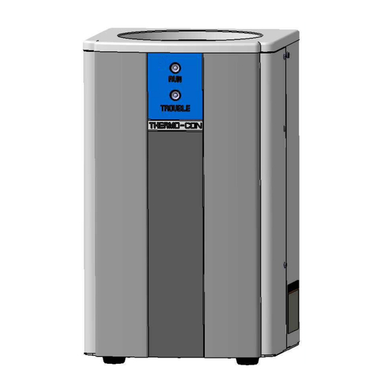
A_HEC-OM-J004 Chapter 2 Description and Function of Each Part Chapter 2 Description and Function of Each Part 2.1 Liquid Tank/Controller ⑭ ⑫ ⑬ ⑧ ② ① Liquid Tank ⑥ ⑤ ④ ⑧ ⑩ ⑦ ⑪ ③ ⑨ Controller ⑫ ⑬ Fig. - Page 18 A_HEC-OM-J004 Chapter 2 Description and Function of Each Part Description Function Communication connector ⑪ Connector for communication with RS-485 or RS-232C. (COMMUNICATION) ⑫ RUN LED(Green) Lights up while the product is running. Lights up when an abnormality occurs. For details, refer to ⑬...
-
Page 19: Chapter 3 Composition And Function Of Product
A_HEC-OM-J004 Chapter 3 Composition and Function of Product Chapter 3 Composition and Function of Product 3.1 Composition The Thermo Electric Bath consists of a Liquid Tank with built-in thermo-modules and a Controller with a built-in DC power supply to actuate the thermo-modules. - Page 20 A_HEC-OM-J004 Chapter 3 Composition and Function of Product The cables attached to this product are designed specifically for this Thermo Electric Bath. Do not use them for other purposes. Also, never use other cables for this product. 3.1 Composition...
-
Page 21: Operating Principles
A_HEC-OM-J004 Chapter 3 Composition and Function of Product 3.1.2 Operating Principles Structure and Principle of Thermo-module A thermo-module (Thermoelectric device) is a unit consisting of multiple semiconductor elements. It can perform cooling and heating freely with direct current, be placed in line for electric purposes and be placed in parallel for thermal purposes. - Page 22 A_HEC-OM-J004 Chapter 3 Composition and Function of Product Operation Principle In this product, many thermo-modules are placed in line between heat exchangers. At one side, cooling water is supplied and at the other side, a tank storing the recirculating fluid is mounted. Both ends of the thermo- modules that are connected electrically in line have a DC power supply whose current is regulated by a Controller.
-
Page 23: Function
A_HEC-OM-J004 Chapter 3 Composition and Function of Product 3.2 Function 3.2.1 Auto Tuning Function This function automatically adjusts the PID values (proportional band, integrating time, and derivative time) necessary for control. To learn how to operate this function, refer to page 5-10, “5.4.7 Details of Initial Setting Mode”. - Page 24 A_HEC-OM-J004 Chapter 3 Composition and Function of Product Table 3-2 Relay contact for temperature deviation alarm Item Specification Output type Relay contact output: Opened when an alarm occurs. 125VAC,0.4A/30VDC,2A (resistive load) Contact rating 125VAC, 0.2A/30VDC,1A (inductive load) Minimum load 5VAC,10mA / 5VDC,10mA Mechanical life 5 million cycles or more Electrical life...
-
Page 25: Offset Function
A_HEC-OM-J004 Chapter 3 Composition and Function of Product 3.2.3 Offset Function This function adjusts the measurement range of the temperature sensor from -1.0 to 1.0 C. The temperature sensor can be calibrated by inputting the difference (calibration value) between the temperatures of a standard thermometer and the temperature sensor. -
Page 26: Alarm Indication On Operation And Display Panel
A_HEC-OM-J004 Chapter 3 Composition and Function of Product 3.2.6 Alarm Indication on Operation and Display Panel Alarms indicated on the operation and display panel are as follows. There is no output generated to the alarm output connector. If this type of alarm occurs, be sure to turn off and restart the power supply once after the trouble causing the alarm is eliminated. -
Page 27: Communication Function
A_HEC-OM-J004 Chapter 3 Composition and Function of Product 3.2.7 Communication Function ・HEBC002-WA10 This product has a communication function conforming to communication protocol RS-485. The transmission cable length, i.e., transmittable distance, is 500m. RS-485 enables one master computer to set and monitor operation conditions of up to 31 Thermo Electric Baths. -
Page 29: Chapter 4 Set-Up
A_HEC-OM-J004 Chapter 4 Set-up Chapter 4 Set-up 4.1 Set-up, Transport and Transfer For set-up, transport and transfer of this product, continue to observe safety precautions, especially those for the human body. Set-up, transfer and maintenance, including dangerous work, must only be performed by people who have sufficient knowledge and experience with this product. -
Page 30: Set-Up In Clean Room
A_HEC-OM-J004 Chapter 4 Set-up Environments having ambient humidity over the following range: Operation 35 to 80% Storage 35 to 85% Environments with sharp temperature changes. Environments generating strong magnetic noise (having a strong electric or magnetic field that generates surges.) ... - Page 31 A_HEC-OM-J004 Chapter 4 Set-up Connect fittings to the ports (Rc1/4) marked “IN” and “OUT” on the Liquid Tank to provide piping for the inlet and outlet of cooling water, respectively. When connecting fittings to the ports, prevent leakage with seal tape or other methods.
- Page 32 A_HEC-OM-J004 Chapter 4 Set-up Keep the cooling water temperature between 10 and 35℃. (No dew condensation) Note that the cooling and heating capacity is changed depending on temperature. Also, when low-temperature cooling water is supplied, dew condensation may occur, damaging the internal electric equipment.
-
Page 33: Quality Of Cooling Water
A_HEC-OM-J004 Chapter 4 Set-up 4.2.2 Quality of Cooling Water Use fresh water (tap water) that satisfies the quality standards shown in Table 4-1 for cooling water. If other liquids are used, the product could break and leak fluid, resulting in electrical shock or earth leakage. -
Page 34: Preparation Of Recirculating Fluid
A_HEC-OM-J004 Chapter 4 Set-up 4.2.3 Preparation of Recirculating Fluid Supply recirculating fluid slowly by using a funnel or a manual pump. The recirculating fluid has effective range of levels. Check that it reaches that range under operating conditions. ... -
Page 35: Draining The Recirculating Fluid
A_HEC-OM-J004 Chapter 4 Set-up Never perform operation under conditions that may create cavitation and lower the fluid level, which could allow the air to enter the fluid and break the pump. To avoid the danger of electrical shock, do not perfom wiring repairs or operate the product with wet hands. - Page 36 A_HEC-OM-J004 Chapter 4 Set-up Take care not to splash the recirculating fluid on the inside of the product and the connectors when draining. If water splashes on the connector or the product body, wipe them off and allow them to dry sufficiently to prevent electrical shock, a short circuit, or ignition.
-
Page 37: Wiring
A_HEC-OM-J004 Chapter 4 Set-up 4.3 Wiring 4.3.1 Earth Leakage Prepare the power supply side for a power supply cable separately. Connect the power supply cable according to page 7-6, “7.3.2 Connection of Power Supply Cable”. This product must be supplied with power through a branch protective circuit and earth leakage breaker rated at 15A or less. -
Page 38: Grounding
A_HEC-OM-J004 Chapter 4 Set-up 4.3.3 Grounding The ground insulation class of this product is class I. Be sure to provide protective ground, which must be class D for Japan (ground resistance of 100ohm or less). Grounding can be provided via the PE line of the power supply cable. -
Page 39: Connection Of Various Types Of Connectors And Power Supply Plugs
A_HEC-OM-J004 Chapter 4 Set-up 4.3.7 Connection of Various Types of Connectors and Power Supply Plugs Ensure that the power supply of the product is turned off before connecting the easy-type connector and power supply plug. If communications lines are used, connect the product and master computer with a shielded cable to reduce the effects of noise. -
Page 41: Chapter 5 Operation
A_HEC-OM-J004 Chapter 5 Operation Chapter 5 Operation 5.1 Start of Operation Confirm that the recirculating fluid has reached the “LOW” level of the tank and supply cooling water to the Liquid Tank. Confirm that there is no incorrect wiring of the connected cables and the power supply cable and turn on the power supply of the Controller. -
Page 42: Setting Of Values
A_HEC-OM-J004 Chapter 5 Operation 5.2 Setting of Values When the product has been found to start operating normally set the values such as temperature. Perform offset adjustment if necessary, referring to page 5-7, “5.4.4 Details of Operation Mode”. Set each value such as set temperature and upper and lower temperature limit. - Page 43 A_HEC-OM-J004 Chapter 5 Operation Check the fluid level at least once a day. The recirculating fluid may evaporate. A significant lowering of the level will cause it to be unable to maintain performance and could break the circulating pump. Maintain the appropriate level at all times.
-
Page 44: Operation Of Controller
A_HEC-OM-J004 Chapter 5 Operation 5.4 Operation of Controller 5.4.1 Details of Operation and Display Panel ① ② ⑦ ⑫ ⑧ ● O U T 1 ● O U T 2 ● ● ● ● ● A L 1 A L 2 C O M R D Y ⑪... -
Page 45: Setting Of Data
A_HEC-OM-J004 Chapter 5 Operation 5.4.2 Setting of Data The Controller has two modes, the operation mode and the setting mode. Each mode has the following content. Operation mode: Normally used. Setting mode: Used to set control values manually ... -
Page 46: Selection Of Operation Mode
A_HEC-OM-J004 Chapter 5 Operation 5.4.3 Selection of Operation Mode When the power supply is turned on, the product is in operation mode. The target temperature is shown as well as the current measured temperature. Each press of the [MODE] key changes the operation mode display as follows. -
Page 47: Details Of Operation Mode
A_HEC-OM-J004 Chapter 5 Operation 5.4.4 Details of Operation Mode <1> Setting of target temp. / Display of measured temp. / Mode indicator (temp. indicator) Initial value: 25.0 Setting range -15.0 to 60.0 PV: Display of measured temp. Indicator SV: Setting of target temp. Indicates measured temp. - Page 48 A_HEC-OM-J004 Chapter 5 Operation [Tips] Status when temp. upper/lower deviation limit alarm ● O U T 1 occurs (at the time of shipment from the factory) ● O U T 2 Lights when ● ● ● A L 1 A L 2 C O M temp.
-
Page 49: Selection Of Setting Mode
A_HEC-OM-J004 Chapter 5 Operation 5.4.5 Selection of Setting Mode Setting mode can be shown by pressing and holding the [MODE] key for approx. 2 sec. Pressing the [MODE] key for approx. 2 sec again will return the setting mode to the normal operation mode. Setting mode selection is indicated with ”... -
Page 50: Selection Of Initial Setting Mode
A_HEC-OM-J004 Chapter 5 Operation 5.4.6 Selection of Initial Setting Mode Inputting “1” in the setting mode ” ” activates the initial setting mode. Each press of the [MODE] key changes the operating mode as follows. Mode indicator 1: Indicates that the initial setting mode is activated. ↓... - Page 51 A_HEC-OM-J004 Chapter 5 Operation <2> Key lock setting / Mode indicator: Initial value: 0 Setting range 0 to 3 Key lock setting Indicates that the key lock setting mode is activated Indicator with “ ”. Sets the key lock function. 0: Lock off Function 1: Full lock (except for the key lock setting)
-
Page 52: Selection Of Control Setting Mode
A_HEC-OM-J004 Chapter 5 Operation 5.4.8 Selection of Control Setting Mode Inputting “2” in the setting mode ” ” activates the control setting mode. Each press of the [MODE] key changes the operating mode as follows. Mode indicator 2: Indicates that the control setting mode is activated. ↓... - Page 53 A_HEC-OM-J004 Chapter 5 Operation [Tips] Indicator for unavailable change If a change in a parameter in the control mode (refer to page 5-12, “5.4.9 Details of Control Setting Mode”) is attempted when “2” (RUN/READY setting) is selected, the indicator as shown on the left appears to show that the change is not available.
- Page 54 A_HEC-OM-J004 Chapter 5 Operation <6> Heating proportional frequency setting / Mode indicator: Initial value: 2 sec. Setting range 1 to 120 sec. Heating for the proportional frequency setting Indicates that the heating for the proportional Indicator frequency setting mode is activated with “ ”.
-
Page 55: Selection Of Ev Output Setting Mode
A_HEC-OM-J004 Chapter 5 Operation 5.4.10 Selection of EV Output Setting Mode Inputting “3” in the setting mode” ” activates the event output setting mode. Each press of the [MODE] key changes the operating mode as follows. Mode indicator <1> 3: EV setting screen ↓... - Page 56 A_HEC-OM-J004 Chapter 5 Operation [Tips] Event output function An event output (condition) is an output (condition) whose purpose is to light up an alarm LED (AL1) and open the contact of a controller alarm output connector (upper/lower deviation alarm) when the product is in the event output range.
- Page 57 A_HEC-OM-J004 Chapter 5 Operation [Tips] Additional functions for the event output function setting Nothing: No additional function. When the product is in the event output range, the event output continues. Holding: When the product attains an event output condition, the event output continues even after the product leaves the event output range.
-
Page 58: Selection Of Communication Setting Mode
A_HEC-OM-J004 Chapter 5 Operation 5.4.12 Selection of Communication Setting Mode Inputting “6” in the setting mode ” ” activates the communication setting mode. Each press of the [MODE] key changes the operating mode as follows. Mode indication <1> 6: Communication setting screen ↓... - Page 59 A_HEC-OM-J004 Chapter 5 Operation <2> Communication speed setting: Mode indicator Initial value: 9.6 Setting range 1.2 to 19.2 (1200bps to 19200bps) Communication speed setting: Indicates the communication speed setting mode is Indication activated with “ ”. Sets the communication speed. The set value can be scrolled with the ▲...
-
Page 60: Initial Value And Setting Range For Each Mode
A_HEC-OM-J004 Chapter 5 Operation 5.4.14 Initial Value and Setting Range for Each Mode Table 5-2 Initial value and setting range for each mode Mode Description Initial value Setting range indicator Setting of target temp. 25.0 -15.0 to 60.0 According to the Offset setting -1.0 to 1.0 Inspection Record... -
Page 61: Alarms
A_HEC-OM-J004 Chapter 5 Operation 5.5 Alarms 5.5.1 Content of Alarms Table 5-3 Content of alarm Temp. (Lit) 7seg. Alarm Subsequent Content of alarm Lit LED Reset upper/lower condition output limit alarm Upper limit temp. alarm (initial setting) Normal Occurs when the sensor value Contact Normal Automatic-... - Page 62 A_HEC-OM-J004 Chapter 5 Operation *3) Except when no function, upper deviation limit, upper/lower deviation limit range, absolute upper limit, or absolute upper/lower limit range is selected in the event output function setting. Refer to page 5-15 “5.4.11 Details of EV Output Setting Mode”. ★Control stop 1: The thermo-module output and pump are stopped.
-
Page 63: Troubleshooting
A_HEC-OM-J004 Chapter 5 Operation 5.5.2 Troubleshooting Table 5-4 Troubleshooting Code Trouble Remedy High-level electric noise has been Move the product to an environment with applied to the power supply line, less noise and restart the power supply. ground line and signal line. If no failure occurs, the noise is the cause. -
Page 65: Chapter 6 Maintenance
A_HEC-OM-J004 Chapter 6 Maintenance Chapter 6 Maintenance This product needs to be returned to the SMC factory for repair and maintenance. Essentially, on-site repairs and maintenance cannot be offered. Before returning the product for repair and maintenance, drain the recirculating fluid from the liquid tank and ensure that it is clean and dry. -
Page 67: Chapter 7 Appendix
A_HEC-OM-J004 Chapter 7 Appendix Chapter 7 Appendix 7.1 Outline Dimensions 7.1.1 Liquid Tank Fig. 7-1 Liquid Tank Fig. 7-2 Internal dimensions of Liquid Tank 7.1.2 Controller Fig. 7-3 Controller 7.1 Outline Dimensions... -
Page 68: Specifications
A_HEC-OM-J004 Chapter 7 Appendix 7.2 Specifications Table 7-1 Thermo Electric Bath specifications Part no. HEBC002-WA10 HEBC002-WB10 Control method Cooling/heating automatic shift PWM control Cooling / Heating method Thermoelectric device (Thermo-module) Liquid Tank Water-cooled Radiating method Controller Forcible air-cooled Operating temp. range -15.0 to 60.0 C (5 C or more for water) (Note 1) (Note 5) - Page 69 A_HEC-OM-J004 Chapter 7 Appendix Note 1) Differs depending on operating conditions. Note 2) Determined under the following conditions: water as the recirculating fluid, set temperature 25℃, cooling water temperature 25℃, flow rate 3L/min, ambient temperature 25℃, and sealed from outside air with a lid. ○...
- Page 70 A_HEC-OM-J004 Chapter 7 Appendix Pollution Degree The pollution degree is a classification from 1 to 4 degrees depending on the pollution present in the air. This product is suitable for environments with a pollution degree of 1 or 2. There is no pollution or only dry and nonconductive pollution occurs.
-
Page 71: Specifications Of Connectors
A_HEC-OM-J004 Chapter 7 Appendix 7.3 Specifications of Connectors 7.3.1 Connection of Liquid Tank and Controller Liquid Tank connector DC connector (male) Signal connector (male) Nanaboshi Electric Mfg.co.,Ltd: Hirose Electric co.,Ltd: CDA-15P(05) NJC-245-RM UL CSA Fixed screw M2.6 Connected Connected ... -
Page 72: Connection Of Power Supply Cable
A_HEC-OM-J004 Chapter 7 Appendix 7.3.2 Connection of Power Supply Cable Controller connector Power supply connector IEC60320 C-14 equivalent Male Connected Power supply cable Controller side IEC60320 C-13 equivalent Female AWG14 Content Black 1 AC100 to 240V (L) Black 2 AC100to 240V (N) Green/Yellow 7.3 Specifications of Connectors... -
Page 73: Connector For External Equipment
A_HEC-OM-J004 Chapter 7 Appendix 7.3.3 Connector for External Equipment Prepare mating connectors for communication connector and alarm output connector by customer separately. Alarm output connector Hirose Electric co.,Ltd: CDE-9P(05) Fixed screw M2.6 Mating connector: CDE-9S(05) equivalent Pin no. Content Temp. -
Page 74: Communication
A_HEC-OM-J004 Chapter 7 Appendix 7.4 Communication 7.4.1 Specifications Table 7-2 Communication Communication type HEBC002-WA10 HEBC002-WB10 Protocol RS-485 RS-232C Circuit type Half duplex Half duplex Communication type Asynchronous Asynchronous Communication speed 1200/2400/4800/9600/19200 1200/2400/4800/9600/19200 (BPS) Character code ASCII ASCII Interface 2-wire 3-wire Parity Without/Odd/Even Without/Odd/Even... -
Page 75: Type Of Message
A_HEC-OM-J004 Chapter 7 Appendix 7.4.3 Type of Message The type of message can essentially be divided into the following categories. Request message Response message (From master) (From this product) Receipt check and data sending Request to read Notice of writing completion Request to write Notice of receiving error and its contents Notice of storage completion... -
Page 76: Composition Of Required Message (From Master To The Product)
A_HEC-OM-J004 Chapter 7 Appendix 7.4.5 Composition of Required Message (from master to the product) Refer to page 7-12 “7.4.7 Explanation of Code” for codes 1 to 10. Composition of request message to read S E B T □ □ R □ □ □ T... -
Page 77: Composition Of Response Message (From The Product To Master)
A_HEC-OM-J004 Chapter 7 Appendix 7.4.6 Composition of Response Message (from the product to master) Refer to page 7-12 “7.4.7 Explanation of Code” for codes 1 to 10. Response message to request message to read S A E B T □... -
Page 78: Explanation Of Code
A_HEC-OM-J004 Chapter 7 Appendix 7.4.7 Explanation of Code ① STX The code necessary for the receiver to detect the beginning of a message. It is put at the beginning of sent characters. ② Address The address to which (this product) the master communicates. The address in a response message from this product shows where the message is sent. - Page 79 A_HEC-OM-J004 Chapter 7 Appendix The negation code included in the “response message” of the product and sent with error type information (refer to “⑩ Error type”) when the received “request message” contains an error. ⑩ Error type When the “request message” received by the product contains an error, the content of the error is included and sent subsequently to the “NAK”...
-
Page 80: Cautions For Communication
A_HEC-OM-J004 Chapter 7 Appendix 7.4.8 Cautions for Communication Pay attention to the following points for communication. ① Operation after the power supply is turned on The product cannot communicate for approx. 6 sec. after the power supply is turned on. (No communication). Allow a time delay before starting communication after the power supply is turned on. - Page 81 A_HEC-OM-J004 Chapter 7 Appendix ⑨ Change of set value (SV) due to communication during auto tuning The set value SV can be changed even during auto tuning. When auto tuning (automatically or manually) is completed, the changed set value will become valid.
-
Page 82: Communication Example
A_HEC-OM-J004 Chapter 7 Appendix 7.4.9 Communication Example Communication example of request message to read Request message from master: Request the product having a set address of 10 to read the measured temperature at that moment. Response message from the product: Send the measured temperature (00250) at that moment. Request message to read (from master) 02 30 31 52 50 56 31 03 65 ②... -
Page 83: Connection (For Rs-485)
A_HEC-OM-J004 Chapter 7 Appendix Request message from master: Request the address having a set address of 10 to set the target temperature to 20.0 Response message from the product: Notice it received the request message properly. ☆ Confirm whether or not data is written correctly by reading the data separately. -
Page 84: Identification Code List
A_HEC-OM-J004 Chapter 7 Appendix A terminal resistance needs to be mounted on the master and slave that are placed the furthest from each other. The resistance must be suitable for the characteristic impedance of the cables used for connection and have a combined resistance of 75 ohms or more. -
Page 85: Performance Chart
A_HEC-OM-J004 Chapter 7 Appendix 7.5 Performance Chart The values shown on the performance chart are representative and not guaranteed. Allow a margin for safety to decide use of the product. 7.5.1 Cooling Capacity Ambient temperature : 25 ℃ Recirculating fluid level : 180 ㎜ (At recirculating fluid temp. 25 ℃ ) Cooling water temp. -
Page 86: Heating Capacity
A_HEC-OM-J004 Chapter 7 Appendix 7.5.2 Heating Capacity Fluorinert FC-3283 Water ○ GALDEN HT200 Ambient temperature : 25 ℃ Recirculating fluid level : 180 ㎜ (At recirculating fluid temp. 25 ℃ ) Cooling water temp. : 25 ℃ Cooling water flow rate : 3L/min Shut out from outside with a lid (styrofoam) Time (... -
Page 87: Cooling Water Pressure Loss
A_HEC-OM-J004 Chapter 7 Appendix 7.5.3 Cooling Water Pressure Loss Ambient temperature : 25 ℃ Cooling water : Tap water Cooling water temperature : 25 ℃ Cooling water flow rate L/min Fig. 7-6 Radiating water pressure loss 7.5 Performance Chart 7-21... -
Page 88: Calculation Of Dew Point Temperature (From Psychrometric Chart)
A_HEC-OM-J004 Chapter 7 Appendix 7.6 Calculation of Dew Point Temperature (from psychrometric chart) Fig. 7-7 Psychrometric chart Measure the ambient temperature and humidity. Plot the ambient temperature on the X axis, “Temp.” (ex. 24 C), and draw a vertical line from there. Find the intersection (A) between the curve with the value closest to the ambient humidity and the straight vertical line. -
Page 89: Chapter 8 Warranty
A_HEC-OM-J004 Chapter 8 Warranty Chapter 8 Warranty (1) Content If the purchased product fails, it will be repaired at no cost within the period and requirements mentioned below. Replacement, adjustment, and inspection of failed parts are all within the range of this warranty, i.e., will be performed at no cost. - Page 91 Revision history Rev 5: May, 2024 https://www.smcworld.com Note: Specifications are subject to change without prior notice and any obligation on the part of the manufacturer. © SMC Corporation All Rights Reserved...
Need help?
Do you have a question about the HEB Series and is the answer not in the manual?
Questions and answers