Table of Contents
Advertisement
Quick Links
Model No. INR-244-733
INR-244-736
INR-244-745
INR-244-747
Copying, duplicating or transferring any part or the entirety of this manual without the
prior permission of SMC is strictly prohibited.
Keep this manual available whenever necessary.
Operation Manual
Thermo Electric Bath
INR-244-734
INR-244-746
INR-244-749
© 2012 SMC CORPORATION All Rights Reserved
HEC-OM-O018-A
June 2012
INR-244-748
INR-244-749
。
Advertisement
Table of Contents

Subscribe to Our Youtube Channel
Related Manuals for SMC Networks INR-244-749


Summary of Contents for SMC Networks INR-244-749
- Page 1 Model No. INR-244-733 INR-244-734 INR-244-748 INR-244-736 INR-244-746 INR-244-749 。 INR-244-745 INR-244-747 INR-244-749 ...
- Page 2 To the customers Thank you for purchasing our Thermo Electric Bath (hereinafter called “product”).SMC always strives to provide the highest quality high-performance temperature control devices to our customers by utilizing our original technology. For the long-term and safe use of this product, be sure to read and understand this Operating Manual (hereinafter called “this manual”) thoroughly before use.
-
Page 3: Table Of Contents
HEC-OM-O018-A Table of Contents Table of Contents Chapter 1 Safety Instructions ............... 1-1 Dangers, Warnings, and Cautions Used in This Manual ........1-1 1.1.1 Hazard Levels ........................1-1 1.1.2 Definitions of “Serious injury” and “Minor injury” ..............1-2 1.1.3 Symbols..........................1-2 Hazard Warning Labels.....................1-4 1.2.1 Content of label ........................ - Page 4 HEC-OM-O018-A Table of Contents Turning ON power ..................... 4-5 Setting of Values ....................... 4-5 Cautions for Operation Control ................4-7 Chapter 5 Operation ................5-1 Operation of Controller..................... 5-1 5.1.1 Details of Controller ......................5-1 5.1.2 Setting of Data ........................5-2 5.1.3 Selection of Operation Mode ....................
-
Page 5: Chapter 1 Safety Instructions
HEC-OM-O018-A Chapter 1 Safety Instructions Chapter 1 Safety Instructions Be sure to thoroughly read and understand the important precautions defined in this manual before using this product. 1.1 Dangers, Warnings, and Cautions Used in This Manual 1.1.1 Hazard Levels These safety instructions are intended to prevent hazardous situations and/or equipment damage. ... -
Page 6: Definitions Of "Serious Injury" And "Minor Injury
HEC-OM-O018-A Chapter 1 Safety Instructions 1.1.2 Definitions of “Serious injury” and “Minor injury” “Serious injury” This term describes injuries such as the loss of eyesight, wounds, burns, frostbite, electric shock, fractures, and toxicity that leave aftereffects, and/or injury requiring hospitalization and/or a prolonged stay in a hospital. “Minor injury”... - Page 7 HEC-OM-O018-A Chapter 1 Safety Instructions Symbol for corrosion This symbol warns of chemical corrosion. When handling chemical fluids, read the MSDS carefully and use appropriate protective equipment. Symbol for inhalation This symbol warns of chemical inhalation. When handling chemical fluids, read the MSDS carefully and use appropriate protective equipment.
-
Page 8: Hazard Warning Labels
HEC-OM-O018-A Chapter 1 Safety Instructions 1.2 Hazard Warning Labels Hazard warning labels are applied to the sections of this system in which potential hazards are present during system operation and maintenance. Hazard warning labels are presented in sizes and colors that will get the attention of the worker. -
Page 9: Location Of Hazard Warning Label
HEC-OM-O018-A Chapter 1 Safety Instructions 1.2.2 Location of hazard warning label Warning label Fig. 1-1 Location of hazard warning label. 1.3 Location of Model Label Fig. 1-2 Location of Model Label 1.3 Location of Model Label... -
Page 10: Safety Measures
HEC-OM-O018-A Chapter 1 Safety Instructions 1.4 Safety Measures 1.4.1 Precautions This product is designed with consideration for safety. However, misuse may result in electrical shock or other accidents. Be sure to keep the following instructions in mind to prevent accidents. The compatibility of the product is the responsibility of the person who designs the equipment or decides its specifications. -
Page 11: Protective Equipment
HEC-OM-O018-A Chapter 1 Safety Instructions Keep within the margin of safety in relation to cooling and heating capacity. When restarting the power supply, wait 3 sec or more after the indications on the display light off. 1.4.2 Protective Equipment Wear protective equipment in order to maintain safety when installing and/or handling the product. -
Page 12: Safety Interlocks
HEC-OM-O018-A Chapter 1 Safety Instructions 1.5 Safety Interlocks For safe use, this product has the following interlocks. *Before reset interlocks, be sure to search and remove cause of interlocks. Table 1-2 Safety Interlocks List Status of product after Content Installation part How to reset* interlock works... -
Page 13: Chapter 2 Description And Function Of Each Part
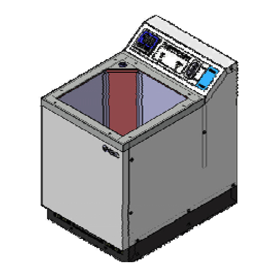
HEC-OM-O018-A Chapter 2 Description and Function of Each Part Chapter 2 Description and Function of Each Part ① ④ ③ ② ⑤ ⑫ ⑥ ⑦ ⑧ ⑬ ⑨ ⑩ ⑪ Fig. 2 Thermo Electric Bath Table 2 Thermo Electric Bath Description Function ①... -
Page 15: Chapter 3 Transporting And Installation
HEC-OM-O018-A Chapter 3 Transporting and Installation Chapter 3 Transporting and Installation 3.1 Transporting Do not service or attempt to remove product and machinery/equipment until safety is confirmed. 1.The inspection and maintenance of machinery/equipment should only be performed after measures to runaway of the driven objects have been confirmed. ... -
Page 16: Installation
HEC-OM-O018-A Chapter 3 Transporting and Installation Avoid strong vibrations and impacts This product is precision equipment and must not be subject to strong vibration and impact during transport. 3.2 Installation 3.2.1 Installation Conditions Keep enough open space to access main power switch and any cable connections. -
Page 17: Installation In Clean Room
HEC-OM-O018-A Chapter 3 Transporting and Installation Environments with sharp temperature changes. Environments generating strong magnetic noise (having a strong electric or magnetic field that generates surges). Environments generating electrical static discharge and conditions in which static electricity is applied to this product. Environments generating strong high frequency radiation (including radio frequency appliances such as mobile phones and tranceivers). -
Page 18: Pollution Degree
HEC-OM-O018-A Chapter 3 Transporting and Installation 3.2.3 Pollution Degree The pollution degree is a classification from 1 to 4 degrees depending on the pollution present in the air. This product is suitable for environments with a pollution degree of 1 or 2. Table 3-1 Pollution degree classification There is no pollution or only dry and nonconductive pollution occurs. -
Page 19: Wiring
HEC-OM-O018-A Chapter 3 Transporting and Installation 3.3 Wiring Only qualified personal are allowed to install wiring. Be sure to turn OFF the power prior to wiring to assure safety. Do not do any wiring when the system is energized. The system wiring requires not only a through connection with the designated cable but also securing to prevent loose connection. -
Page 20: Connector For External Equipment
HEC-OM-O018-A Chapter 3 Transporting and Installation Power supply connector IEC60320 C-14 equivalent Male Table 3-4 Power supply connector ITEMS 100 ~ 240VAC 100 ~ 240VAC (N) Fig. 3-2 Power supply connector 3.3.3 Connector for External Equipment The alarm output and communication cables are to be prepared under your responsibility, referring to the following table. -
Page 21: Procedures For Wiring Instllation
HEC-OM-O018-A Chapter 3 Transporting and Installation Communication connector D-SUB 9pin (female) Fixed screw M2.6 Table 3-6 Communication connector Pin no. Content INR-244-733/-734/ INR-244-745/-746/ -736/-748 -747/-749 RS-485 T/R(A) Unused RS-485 T/R(B) RS-232C RxD Unused RS-232C TxD Unused Unused Unused RS-232C GND Fig. -
Page 22: Installation Of Facility Water Piping
HEC-OM-O018-A Chapter 3 Transporting and Installation 3.4 Installation of Facility Water Piping Confirm that the tube is not bent to the point where it is kinked and may prevent facility water flow. Connect fittings to the ports marked “IN” and “OUT” on the product to provide piping for the inlet and outlet of Facility Water, respectively. -
Page 23: Chapter 4 System Set-Up
HEC-OM-O018-A Chapter 4 System Set-up Chapter 4 System Set-up 4.1 Pre-check Check the following items prior to starting up the product. Make sure that the product is installed in horizontal position. Refer 3.2 Installation Make sure proper connection of the power supply cable, ground, alarm output, and communication cables. -
Page 24: Facility Water Run Through
HEC-OM-O018-A Chapter 4 System Set-up 4.2.2 Facility water run through Make facility water run through. Make sure there is no leakage on the facility water circuit. Check if adequate fluid is in the bath. If the facility water pipings are arranged in parallel, the flow rate may not be adequate. - Page 25 HEC-OM-O018-A Chapter 4 System Set-up Table 4-2-2 Bath Capacity Model Number Bath Capacity (Approx.) INR-244-733/-736/-745/-747 10.2 Litter (2.7 gal) INR-244-734/-746 23.1 Litter (6.1 gal) INR-244-748/-749 38.8 Litter (10.2 gal) Do not use tap water or hard water. Use of these waters can cause the internal pump failure and the performance deterioration by generation of scale.
- Page 26 HEC-OM-O018-A Chapter 4 System Set-up 4.3.2 Filling Bath Liquid Make sure the drain port is plugged. Make sure the strainer is installed correctly. Supply bath liquid slowly. Do not pour bath liquid to the controller. Fill bath liquid up to a maximum level of 30 mm below the top of the bath. In case the liquid level is low, it may have cooling capacity deteriorate because the internal pump may have aeration.
-
Page 27: Turning On Power
HEC-OM-O018-A Chapter 4 System Set-up 4.4 Turning ON power Make sure that Main power switch is OFF. Turn ON the power breaker on primary side (your tool side). Turn ON Main power switch. Controller will indicate the current Bath liquid temperature after approx. 6 sec. - Page 28 HEC-OM-O018-A Chapter 4 System Set-up Alarm indication on the display Indicator Content Shown when a temperature sensor is opened . Shown when a temperature sensor is short circuited. Shown when Contoroller has a memory error. Shown when Controller has an A/D conversion error.
-
Page 29: Cautions For Operation Control
HEC-OM-O018-A Chapter 4 System Set-up 4.6 Cautions for Operation Control If an alarm comes on during operation, refer to page 5-14, “5.2.1Content of Alarms”, for the remedy. When low-temperature Facility Water is supplied, dew condensation may occur, damaging the internal electric equipment. Keep the Facility Water temperature over the atmospheric pressure dew point. -
Page 31: Chapter 5 Operation
HEC-OM-O018-A Chapter 5 Operation Chapter 5 Operation 5.1 Operation of Controller 5.1.1 Details of Controller ① ② ⑦ ⑫ ⑧ ● O U T 1 ● O U T 2 ● ● ● ● ● A L 1 A L 2 C O M R D Y ⑪... -
Page 32: Setting Of Data
HEC-OM-O018-A Chapter 5 Operation 5.1.2 Setting of Data Controller has two modes, Operation mode and Setting mode. Each mode has the following content. Operation mode: Normally used. Setting mode: Used to set control values manually Selection of mode Operation mode: Initial mode Setting mode: Press and hold [MODE]key for 2 sec. -
Page 33: Selection Of Operation Mode
HEC-OM-O018-A Chapter 5 Operation 5.1.3 Selection of Operation Mode When the power supply is turned on, the product is in operation mode. The target temperature is shown as well as the current measured temperature. Each press of the [MODE] key changes the operation mode display as follows. -
Page 34: Details Of Operation Mode
HEC-OM-O018-A Chapter 5 Operation 5.1.4 Details of Operation Mode Target Temp./Measured Temp. Indication and Target Temp. Setting <1> Sets target temperature Set with [▲] or [▼] key Function Indicates current temperature on PV and target temperature on SV Setting range 0.0 ~ 60.0 Initial value 25.0... - Page 35 HEC-OM-O018-A Chapter 5 Operation [Tips] Status when High/Low temp. alarm occurs ● O U T 1 ● Lights up when O U T 2 AL1 LED lights up when High/Low temp. alarm occurs. ・ High/Low temp. ● ● ● A L 1 A L 2 C O M The alarm signal is output from the alarm output...
-
Page 36: Selection Of Setting Mode
HEC-OM-O018-A Chapter 5 Operation 5.1.5 Selection of Setting Mode Setting mode can be shown by pressing and holding the [MODE] key for approx. 2 sec. Pressing the [MODE] key for approx. 2 sec again will return the setting mode to the normal operation mode. Setting mode selection is indicated with ”... -
Page 37: Selection Of Initial Setting Mode
HEC-OM-O018-A Chapter 5 Operation 5.1.6 Selection of Initial Setting Mode Selecting “1” in Setting mode ” ” activates the Initial setting mode. Each press of the [MODE] key changes the operating mode as follows. Mode indicator 1 Indicates that Key Lock Setting Mode is activated. ... -
Page 38: Selection Of Control Setting Mode
HEC-OM-O018-A Chapter 5 Operation 5.1.8 Selection of Control Setting Mode Selecting “2” in the setting mode ” ” activates the control setting mode. Each press of the [MODE] key changes the operating mode as follows. Mode indicator 2: Indicates that the control setting mode is activated. ↓... -
Page 39: Details Of Control Setting Mode
HEC-OM-O018-A Chapter 5 Operation 5.1.9 Details of Control Setting Mode <1> Control Mode Setting Sets control mode. Function Select with the “ ▲ ” and “ ▼ ” keys. Temperature control enabled ・ Selectable Temperature control disabled) Setting Manual control) Initial Setting Do not select Temperature control function is disabled when... - Page 40 HEC-OM-O018-A Chapter 5 Operation <4> Derivative Time Setting Sets the derivative time used for PID control. Function Set with [▲] or [▼] key 0 ~ 3600 sec. Setting range If “0” is set, derivative control is disabled. Initial value 0sec <5>...
-
Page 41: Selection Of Communication Setting Mode
HEC-OM-O018-A Chapter 5 Operation 5.1.10 Selection of Communication Setting Mode Inputting “6” in the setting mode ” ” activates the communication setting mode. Each press of the [MODE] key changes the operating mode as follows. Mode indication Indicates that communication setting mode is activated. ... - Page 42 HEC-OM-O018-A Chapter 5 Operation <2> Communication speed setting Sets the communication speed. The set value can be scrolled with the ▲ and ▼ keys. Function 1.2 ⇔ 2.4 ⇔ 4.8 ⇔ 9.6 ⇔ 19.2 Selectable setting 2.4 ~ 38.4 (2400 bps ~ 38400 bps) Initial setting 9.6 (9600 bps) <3>...
-
Page 43: Initial Value And Setting Range For Each Mode
HEC-OM-O018-A Chapter 5 Operation 5.1.12 Initial Value and Setting Range for Each Mode Table 5-2 Initial value and setting range for each mode Mode Description Setting range Initial value indicator Setting of target temp. 0.0 to 60.0 25.0 According to the Offset setting -1.0 to 1.0 Inspection Record... -
Page 44: Alarms
HEC-OM-O018-A Chapter 5 Operation 5.2 Alarms 5.2.1 Content of Alarms Table 5-3 Content of alarm (Lit) 7seg. Alarm Unit High/Low Content of alarm Lit LED Reset temp. alarm output Status High temp. alarm Normal Contact Normal Automatic- Occurs when the bath liquid temp is status opened operation... -
Page 45: Troubleshooting
HEC-OM-O018-A Chapter 5 Operation 5.2.2 Troubleshooting Table 5-4 Troubleshooting Cause Countermeasure Code Move the product to an environment with High-level electric noise is applied to less noise and restart. the power supply line, ground line If no failure occurs, the noise caused the and/or signal line. - Page 46 HEC-OM-O018-A Chapter 5 Operation Table 5-4 Troubleshooting (continue) Cause Countermeasure Code Check if the cable is disconnected. If the trouble cannot be solved even after no The temperature sensor is broken disconnection is confirmed, confirm there (or the cable is disconnected). is no broken wire.
-
Page 47: Chapter 6 Maintenance
HEC-OM-O018-A Chapter 6 Maintenance Chapter 6 Maintenance 6.1 Regular Maintenance Check that the strainer is not clogging in regular interval. Check the concentration of the bath liquid in regular interval. (Concentration of Ethylene glycol must be lower than 50%) Replace the bath liquid in regular interval. Work sequence when replace the bath liquid or clean the strainer 1.Power off 6-2-1 ... -
Page 48: Draining The Bath Liquid
HEC-OM-O018-A Chapter 6 Maintenance 6.1.1 Draining the Bath liquid Stop the product (turn off main power switch and cut the facility water flow) and remove all the connected cables and piping before draining. Please prepare the fitting suitable for prompt separation (PLCD16004) and exhaust the liquid from the drain. -
Page 49: Before Returning The Product
HEC-OM-O018-A Chapter 6 Maintenance 6.2 Before returning the product This product needs to be returned to the SMC factory for repair and maintenance. Essentially, on-site repairs and maintenance cannot be offered. Obtain the form “Request for Return” from our sales branches. The purpose of this form is to ensure that the returned product is safe. -
Page 51: Chapter 7 Appendix
HEC-OM-O018-A Chapter 7 Appendix Chapter 7 Appendix 7.1 Outline Dimensions 7.1.1 INR-244-733/-736/-745/-747 Fig. 7-1-1 Overall sizes of product (INR-244-733/-736/-745/-747) Bath dimensions INR-244-733/-736/-745/-747) Fig.7-1-2 7.1 Outline Dimensions... -
Page 52: Inr-244-734/-746
HEC-OM-O018-A Chapter 7 Appendix 7.1.2 INR-244-734/-746 7-1-3 Overall sizes of product (INR-244-734/-746) Fig. 7-1-4 Bath dimensions (INR-244-734/-746) Fig. 7.1 Outline Dimensions... -
Page 53: Inr-244-748/-749
HEC-OM-O018-A Chapter 7 Appendix 7.1.3 INR-244-748/-749 Fig. 7-1-5 Overall sizes of product (INR-244-748/-749) Fig. 7-1-6 Bath dimensions (INR-244-748/-749) 7.1 Outline Dimensions... -
Page 54: Specifications
HEC-OM-O018-A Chapter 7 Appendix 7.2 Specifications Table 7 Thermo Electric Bath specifications INR-244 Model No. -733 -745 -736 -747 -734 -746 -748 -749 Control method Cooling/heating automatic shift PWM control Cooling/Heating method Peltier element (Water-cooled) Operating temp. range 0.0 to 60.0 C (5 C or more for water) (Note 1) (Note 5) Temp. - Page 55 HEC-OM-O018-A Chapter 7 Appendix leaks out. Otherwise, peripheral equipment as well as the thermo electric bath can break. 2. When the set temperature is increased from a low value to an ordinary value, some kinds of the bath liquid can swell, increase and overflow, which can not only break the thermo electric bath and other equipment, but also cause a serious accident.
-
Page 56: Performance Chart
HEC-OM-O018-A Chapter 7 Appendix 7.3 Performance Chart The values shown on the performance chart are representative and not guaranteed. Allow a margin for safety to decide use of the product. 7.3.1 Cooling Capacity Ambient temperture: 25℃ Bath liquid: Water Liquid measure: Max. liquid level INR-244-734/-746 Facility water: 25℃, 3L/min Shut out from outside with a lid INR-244-748/-749 INR-244-733/-745 Time(minutes) Fig. -
Page 57: Facility Water Pressure Loss
HEC-OM-O018-A Chapter 7 Appendix 7.3.3 Facility Water Pressure Loss 0.020 0.018 0.016 0.014 0.012 INR-244-734/-736/-746/-747/-748/-749 0.010 INR-244-734/736/746/747 0.008 0.006 0.004 INR-244-733/-745 0.002 INR-244-733/745 0.000 Facility water flow rate (L/min) Cooling water flow rate L/min Fig. 7-4-3 Facility water pressure loss 7.3 Performance Chart... -
Page 59: Chapter 8 Warranty
HEC-OM-O018-A Chapter 8 Warranty Chapter 8 Warranty 8.1 Limited warranty and Disclaimer/Compliance Requirements The product used is subject to the following “Limited warranty and Disclaimer” and “Compliance Requirements”. Read and accept them before using the product. (1) Content If the purchased product fails, it will be repaired at no cost within the period and requirements mentioned below. -
Page 60: Compliance Requirements
HEC-OM-O018-A Chapter 8 Warranty Disclaimer The following are not covered by this warranty. ① Expenses to compensate for secondary damages to other equipment and goods due to the failure of the product ② Expenses for repairs performed by other companies ③... - Page 61 Revision history 4-14-1, Sotokanda, Chiyoda-ku, Tokyo 101-0021 JAPAN Tel: + 81 3 5207 8249 Fax: +81 3 5298 5362 http://www.smcworld.com Note: Specifications are subject to change without prior notice and any obligation on the part of the manufacturer. © 2012 SMC Corporation All Rights Reserved...
Need help?
Do you have a question about the INR-244-749 and is the answer not in the manual?
Questions and answers