
Related Manuals for SMC Networks Rapidox SF6 6100


Summary of Contents for SMC Networks Rapidox SF6 6100
- Page 1 6100 Pump Back Analyser Instruction Manual 5840 S. Memorial Drive Suite 208 Tulsa, Oklahoma 74145 Tel. 918-622-5725 Fax. 918-664-2073 sales@noramsmc.com...
- Page 2 Warnings Electrical Shock Hazard Do NOT remove internal metal panel There are no user-serviceable parts in this unit Do not attempt to repair the analyser yourself Refer all servicing to qualified personnel The unit should not be exposed to extreme temperatures <...
-
Page 3: Table Of Contents
Warnings HF & SO are toxic and can be fatal if inhaled HF & SO cause severe skin burns HF causes severe damage to the eyes H S & CO are toxic and can be fatal if inhaled ... -
Page 4: Introduction
Pump Back Option ........................20 Start Delay ........................... 21 Working with Pre-Loaded Test Parameters ..............22 Working with SF and N mixtures ..................23 Working with SF and Air mixtures................... 24 Working with SF and CF mixtures .................. 25 Rapidox Menu System ........................27 Calibrate ............................ -
Page 5: Technical Specification
The sample gas can be used if the inlet pressure is between 0.3 bar and 10.0 bar. The analyser has a full pump back facility allowing any gas stored inside the analyser to be re-pressurised and returned to the SF compartment. - Page 6 Warm up time 15 minutes at 20°C Temperature -10°C to 40 Normal operating conditions Humidity 10 to 90% RH Pressure 800 to 1100 mbar absolute. Minimum Gas Inlet Pressure 0.3 bar Maximum Gas Inlet Pressure 10 bar Maximum Pump Back Pressure 10.5 bar Data Output Via USB memory stick or thermal printer...
-
Page 7: Analyser Description
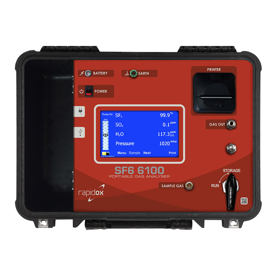
3 Analyser Description Figure1: Layout of the SF 6100 Pump Back Analyser Main display and touch screen menu system Thermal printer Sample gas inlet (via closed coupled fitting) Earth fixing point Gas flow indicator on the display Power on/off switch LED battery charging lights USB memory stick port Fuse holders (see Table 1) -
Page 8: Getting Started
4 Getting Started The two labelled fuses will be removed for transportation safety reasons. There are two fuses located in fuse holders labelled with the values listed in Table 1. This completely isolates the lithium batteries. These fuses are different and must not be mixed up. The fuses should be inserted into the correct holders (9) and fixed into position before first use. -
Page 9: Advisory Screens
4.2 Advisory Screens During sampling, line purge and pump back the analyser checks to see if the sample line hose is correctly fitted to ensure that the cycle works correctly and doesn’t allow any contamination of the compartment gas with air, or any SF is allowed to escape into the atmosphere. -
Page 10: Performing A Test
Figure 2: Examples of different on-screen help messages you may encounter during operation. The screen message includes text prompts explaining what action to perform. 5 Performing a Test With the analyser switched on and ready, use this guide to prepare the machine for testing and complete an analysis. -
Page 11: Preparing The Analyser
Figure 4: Use this option to change the sampling method to “Timed” or “continuous” and set the sampling duration and other options. An initial set up is recommended as follows (see 7.4 for full details): Measurement Mode: Set this to TIMED. Sample Duration: This is fixed to 8 minutes and the option is greyed out Start Delay: Set this to 0 unless you must walk away from the equipment before a test starts. - Page 12 Make sure that the sample line hose is clean and dry. A brand new 2m long sample hose is supplied pre-pressurised with dry SF at 5bar pressure. Take the male end of the hose and insert it into the Sample Gas Inlet as shown in Figure 5. Do NOT attach the other end to anything yet.
-
Page 13: Sampling
Connect the Rapidox sample hose to the analyser but NOT the gas compartment Figure 6: Screen message displayed when attempting a line purge. 5.4 Sampling Once the line purge is completed press SAMPLE to begin the test. You will be instructed (see Figure 7) to connect the female coupling on the end of the hose to the gas compartment using a DILO male coupling adapter (supplied). -
Page 14: Results And Finishing
Sample gas is flowing Storage bag is empty Figure 8: Screen message displayed when performing a Timed analysis. The test will take eight minutes to complete. Once the hose is correctly connected you will see the Gas Inlet Pressure Meter (see Figure 8) rise and the pressure display will indicate the gas compartment pressure. -
Page 15: Notes About Dewpoint Measurements
Note that if you are testing very small volume circuit breakers at low pressures then it is NOT recommended to do repeated testing as continual sampling and pumping back can eventually make a noticeable change in the gas quality; particularly the overall moisture content. - Page 16 Figure 9: Operational Flow Chart...
-
Page 17: Operational Description
6 Operational Description 6.1 Main Screen Figure 10: Main operation screen (RED) configured with just three sensors, showing sensor readings with side panel (YELLOW) indicating the gas flow, bag, battery and pressure status During sampling the target gas flow is factory set to 0.5L.min and this is displayed on the side panel using the electronic gauge (Figure 10 –... -
Page 18: Live Graph Display
The gas storage gauge will give you an indication of how full the internal storage bag is. The bag will hold up to five litres of gas at standard temperature and pressure. This is more than sufficient capacity to complete a single eight-minute timed test in normal atmospheric conditions including at high altitude. - Page 19 with the SF . If you are doing a series of tests it is not necessary to line purge every time as the hose will be full of SF from the previous test. The small volume of residual gas in the sample hose that is removed during the line purge operation is vented to the “Bypass Port”...
-
Page 20: Pump Back Option
6.4 Pump Back Option If you have completed a test, or have gas in the storage bag, or have a bag that is full then you can pump the gas back in to the gas compartment or gas recovery unit with this option. You will receive a screen message and a diagram asking you to check and confirm the sample hose is connected to the gas compartment (Figure 2 –... -
Page 21: Start Delay
6.5 Start Delay In certain test environments, you are required to walk away from the equipment while the test is being performed. The Rapidox allows the user to enter a start delay time in the Sampling Menu. When enabled, the unit will count down the delay time before starting a test. -
Page 22: Working With Pre-Loaded Test Parameters
Figure 15: The delayed start is shown on the screen before a sample commences 6.6 Working with Pre-Loaded Test Parameters The Rapidox has several commonly used SF test parameters pre-loaded for quick and easy selection. The list includes CIGRE and IEC international test standards as well as the option to create and name your own custom test. -
Page 23: Working With Sf And N Mixtures
On this screen the user can remove any tests by pressing “None”. This will clear all previous selections. To select the relevant test simply press on the labelled button of choice and the pass/fail alarm settings will be loaded as displayed. Or if the user wants to create a new bespoke test click on the button labelled “Custom”... -
Page 24: Working With Sf And Air Mixtures
Figure 18: Use the System Control Menu to switch on / off the Balance Gas option Select YES and press SET. The analyser will respond by asking to re-boot to enable this function. Once restarted the main screen will now display N as the balance gas. -
Page 25: Working With Sf And Cf Mixtures
Figure 20: With the balance gas option enabled it is possible to change the display units from “N ” to “Air” if required. Figure 21: With Air selected as the unit for the balance gas, the display now looks like this. The balance mode can be enabled or disabled ay time by the use by accessing the System Control Menu. - Page 26 In certain cold countries SF is blended with carbon tetrafluoromethane (CF ) normally in a 50:50 mix. This is used as an anti-freeze to prevent the SF from becoming liquid at extreme cold temperatures. This Rapidox will correctly measure the SF and CF content of your gas mixture in the range specified using a combination of sensor readings and mathematics.
-
Page 27: Rapidox Menu System
7 Rapidox Menu System Pressing “Menu” enters the main Rapidox Menu system as seen below. Press “Back” to return to the main analyser screen. If padlocks are displayed then these options are password protected. See 7.9 for more information on passwords. Figure 24: Rapidox Main Menu Screen. - Page 28 Figure 25: Main calibration screen During calibration, the cal gases are either diverted through the analyser and ejected via the Bypass Port (Figure 1-15) so no gas enters the storage bag (set unit to CONTINUOUS mode) or the cal gases enter the internal storage bag so no gas escapes intro the atmosphere (set unit to TIMED mode).
- Page 29 are displayed on the calibrate screen as seen in Figure 25 above but these can be changed if they do not match the value of your gas bottle. You can load a previous calibration by pressing “Load” and you can save the calibration you have just performed by pressing “Save”.
- Page 30 Figure 29: The zero and span calibration gas concentrations can be modified by the user Once you are happy that the reading is stable press “Cal” to save the new calibration. Use the “Out” button to redraw the graph full scale. Use the “Back” button to return to the main calibration screen.
-
Page 31: Data-Logging
7.2 Data-Logging The test set data-logs all parameters and test results constantly whilst the machine is operating. The data is stored indefinitely until the hard drive is full and then data will be overwritten oldest first. There is sufficient space on the hard drive for a minimum of twelve months of continuous data storage based on how the unit is used. - Page 32 Figure 32: The Data is loaded from the hard disc drive and displayed on the screen To display the basic test result press “Show Results”. The result information will be displayed as follows: Figure 33: The Data is loaded from the hard disc drive and displayed on the screen. Here it can be printed out.
- Page 33 Figure 34: Historical data-log graph with colour coded key Figure 35: RGB Colours used for each gas type shown on a graph. Not all gas types are fitted to Rapidox machines. Pressing “Back” and “Next” will redraw the graph with a single gas or parameter to aid with clarity.
-
Page 34: Auto Abort
Figure 36: The user can customise the historical graphs using the “Options” button and selecting which sensors to display and which to hide. 7.3 Auto Abort The Auto Abort function allows users to set limits for toxic gases entering the analyser. This helps to prevent damage to the equipment if excessive amounts of harmful gases such as SO S, CO and HF enter the pipework. -
Page 35: Sampling Modes
Note that you cannot set over-gas limits for SF and H O. Only the toxic gas sensors fitted to your machine will be listed here. Toggle the Enable/Disable button to switch on the over-gas protection. Press on the gas value to edit the over-gas set point. Toggle the pumpback switch to “Auto”... -
Page 36: Timed Mode
For both modes There is an option to identify the sample with a name (e.g. “GIS Station 3”) that is displayed on the main screen. This name is also recorded on the data log file and on the print out. 7.5 Timed Mode Figure 39: Use this option to change the sampling method from “Timed”... - Page 37 will force the analyser to pump back the gas into the compartment after each set of tests is completed. This is a normal procedure, so it is suggested to leave this set to “Auto”. Both these options can also be manually commanded from the main display screen as well. Note that if you choose multiple tests using the “Number of Tests”...
-
Page 38: Continuous Mode
Figure 42: If during sampling the user wants to escape, pressing the “Abort” button will stop the sample and the screen will show -.- to indicate that the sample was incomplete. 7.6 Continuous Mode Figure 43: Continuous Mode set up page This mode is used only when calibrating, validating or servicing the analyser. -
Page 39: Set Units
connected to the port. Note that each time the analyser is started, a reminder screen will be displayed as shown in Figure 2 number 5). In this mode the start delay option is still available. See 6.5 for a full description of this feature. -
Page 40: Passwords
There are various options for setting the analyser date and time and how it is displayed. This information appears in the bottom left-hand corner of the display and is used for data- logging and record keeping. Figure 45: Use this screen to set the date and time and how it should be displayed on the main screen. 7.9 Passwords Default password USER = 2222 Default password ADMIN = 8888... - Page 41 Figure 46: To enter the password menu the user must enter the Admin password. The factory default is 8888. Once you have entered the password menu as the Administrator then you can set the restrictions and change the passwords as you so desire. There is an Admin password (used to enter only the password screens) and a user password (used to access menus and options on the analyser).
- Page 42 Figure 48: Once a password is enabled the user password will have to be entered to gain access to the menu button that is locked. Press “Set” to store the new settings. Please contact SMC for advice about how to recover a lost Administrator password.
-
Page 43: Options Menu System
8 Options Menu System The Options Menu displays various settings that the user may use to set the analyser up initially. Also included here are some diagnostics and other system tools. The “Data Transfer” button remains grey until you insert a memory stick into the socket (8) as shown in Figure 49. - Page 44 Figure 50: Use this screen to select the range of data to transfer onto your memory stick Figure 51: Press “Copy” to begin the transfer. Do not remove the memory stick until told to do so.
- Page 45 Figure 52: It is now safe to remove the USB memory stick. The individual results file is in csv format that can be opened directly into Excel. Each test is listed in order of date and time and each sensor result is placed on an individual row:...
- Page 46 Figure 53: Basic test results downloaded from the Rapidox are easily imported into an Excel spread sheet. The complete data log files are also in csv format and can be opened directly into Excel. This time the tests can be re-graphed as shown in Figure 54 using the functions available in Excel.
-
Page 47: System Control
Figure 54: Data from the Rapidox is easily imported into an Excel spread sheet. 8.2 System Control This options menu is used to set how the line purge and pump back operates and to manually allow a purge of the complete system. As a complete system purge can involve releasing small amounts of SF into the atmosphere if precautions have been ignored it is generally a password controlled menu option. -
Page 48: Gas Cylinder Testing
Figure 56: For analysers NOT fitted with CF4 option this is what is displayed. Pressing “System Purge Now” will perform a complete vacuum purge of the analyser including all pipework, sample hose and gas storage bag. This is normally only required if the analyser has just been calibrated and the user needs to purge the system of calibration gas, or contaminated gas has been allowed to enter the machine. -
Page 49: Auto N System Clean
analyser will accept gas directly from a gas bottle fitted with a regulator. A small gas cylinder icon is displayed on the main screen to indicate this mode is in operation. When sampling directly from gas bottles, it is normal for the regulator pressure to drop momentarily when the test begins and in “normal”... -
Page 50: Screen Colour
Figure 57: Use this option to change the language setting of the analyser. Requires a system re-boot. Not all options are shown on this screen Figure 58: The analyser will ask you to confirm you really want to change the language before performing a re-boot. -
Page 51: Screen Brightness
8.7 Screen Brightness The brightness of the screen can be increased or decreased using this menu option. The screen brightness does have a significant impact on the battery life of the instrument. There is also a screen saver option that can be enabled or disabled to help increase battery life. -
Page 52: Restore
Figure 61: Diagnostics Page 8.9 Restore This screen can be accessed and used to perform a factory restore of the analyser. In normal circumstances this would only be required is the user is experiencing difficulties with a calibration. Note that all data is lost during a factory restore and the sensors will require a fresh calibration afterwards as only a basic calibration is loaded. -
Page 53: Troubleshooting
Figure 63: This screen shows important system information about the analyser and sensors connected. 9 Troubleshooting When I switch on the unit the SF sensor display says “Wait”. The infra-red SF sensor needs a bit of extra time to warm up before it can give readings. - Page 54 The H O sensor reading shows “U/Range” right after I perform a line purge. This is quite normal and caused by the fact the dewpoint sensor is sitting in a vacuum. Because of the pressure compensation maths the reading can be pushed below its minimum for a moment but this will fully recover once pressurised compartment gas is applied.
- Page 55 this mode without CF present, then the results will be inaccurate. The SF reading seems very inaccurate Please check the settings MENU – SAMPLING and check to see if the CF option is set to yes or no. If it is set to yes and there is no CF in the gas then the SF reading will be inaccurate.
-
Page 56: Warranty
dewpoint both at actual temperature (RT) and at the corrected point (@20°Cdp). In hot countries this produces a drier reading and in colder countries this produces a wetter reading. And of course if the ambient temperature is 20°C then the readings are both identical. - Page 57 a] Notice in writing of the defects complained of shall be given to SMC (The Seller) upon their appearance, and b] such defects shall be found to have arisen from the Seller's faulty design, workmanship or materials, and c] The defective goods shall be returned to the Seller's premises at the Purchaser's expense if so requested by the Seller.
Need help?
Do you have a question about the Rapidox SF6 6100 and is the answer not in the manual?
Questions and answers