Advertisement
USE AND CARE GUIDE
Questions, problems, assembly help, missing parts?
We will gladly help and ship your replacement parts free of charge.
If you have any question related to product, please free to contact our customer
THIS INSTRUCTION CONTAINS IMPORTANT SAFETY INFORMATION.
PLEASE READ AND KEEP FOR FUTURE REFERENCE.
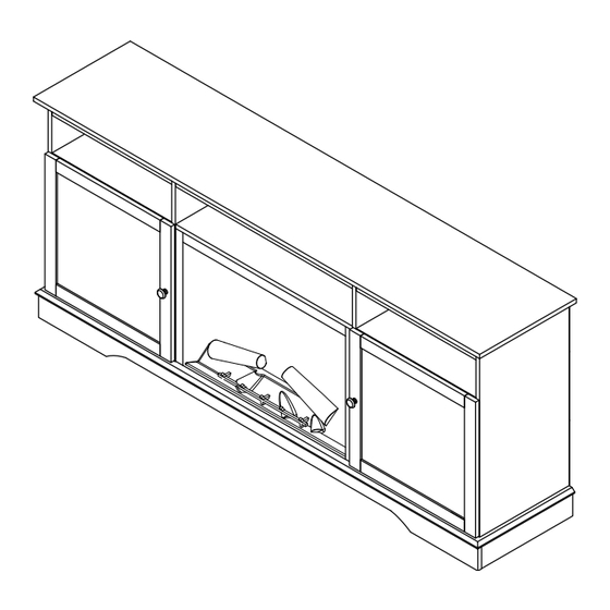
FIREPLACE WITH 2 DOORS
IMPORTANT
service mail:
service@velayhome.com
pris@pmvelay.com
IMPORTANT
1
Model#: VL-M04DB72F
VL-M04LB72F
Advertisement
Table of Contents

Related Manuals for Valuxhome VL-M04DB72F


Summary of Contents for Valuxhome VL-M04DB72F
- Page 1 Model#: VL-M04DB72F VL-M04LB72F USE AND CARE GUIDE FIREPLACE WITH 2 DOORS IMPORTANT Questions, problems, assembly help, missing parts? We will gladly help and ship your replacement parts free of charge. If you have any question related to product, please free to contact our customer service mail: pris@pmvelay.com...
-
Page 2: Before You Start
WARNING ! - Do not allow children to climb on unit. - Serious or fatal crushing injuries can occur from furniture tip-over, to prevent this furniture from tipping over it must be permanently fixed to the wall. - Fixing devices for the wall are not included since different wall materials require different types of fixing devices. - Page 3 HARDWARE PART LIST NOT SHOW ACTUAL SIZE Cam Lock Cam Bolt Wood Dowel Screw Screw Screw...
-
Page 4: Angle Bracket
HARDWARE PART LIST NOT SHOW ACTUAL SIZE Shelf Support Bolt Hinge Knob Screw Angle Bracket... -
Page 5: Board Identification
BOARD IDENTIFICATION NOT SHOW ACTUAL SIZE... - Page 6 STEP 1 1. Unpack the unit and confirm that you have all the hardware and required parts. Assembly the unit on a carpeted floor or the empty carton to avoid any scratch. 2. Securely screw the Cam Bolts (2) into the designated small holes of Part (O), Part (P), Part (R), Part (Q) as shown. Fully tighten with a Phillips screwdriver.
- Page 7 STEP 2 1. Align and attach the Part (O) and Part (P) to the Part (Q) by using the Cam Locks (1). 2. Then attach the Part (R) to the Part (O) and Part (P) by using the Cam Locks (1) as shown.
- Page 8 STEP 3 Securely screw the Cam Bolts (2) into the designated small holes of Bottom (B) as shown.
- Page 9 STEP 4 1. Attach the assembled Part (O), Part (P), Part (Q) and Part (R) to the Bottom (B) with sixteen Cam Locks (1). 2. Then turn it over and securely screw the Cam Bolts (2) into the designated small holes of Bottom (B) as shown.
- Page 10 STEP 5 1. Insert the Wood Dowels (3) into the Left Side (F), Right Side (G), and Shelves (C) as shown. 2. Securely screw the Cam Bolts (2) into the designated small holes of Left Side (F) and Right Side (G) as shown.
- Page 11 STEP 6 1. Securely screw the Cam Bolts (2) into the designated small holes of Left Partition (H) as shown. 2. Turn it over and insert the Wood Dowels (3) into the Left Partition (C) as shown, then securely screw the Cam Bolts (2) into the designated small holes of Left Partition (H) as shown.
- Page 12 STEP 7 1. Repeat last step to assemble the Right Partition (I) as shown.
- Page 13 STEP 8 1. Position the Left Vertical (M) onto the inserted Wood Dowels and insert Screws (4) through the countersunk holes on the Left Vertical (M), and screw into the Left Partition (H) as shown. 2. Repeat to assemble the Right Vertical (N) to the Right Partition (I) as shown.
- Page 14 STEP 9 1. Insert the Wood Dowels (3) into the Middle Shelf (D) as shown. 2. Position the Rail (L) onto the inserted Wood Dowels and insert three Screws (4) through the countersunk holes on the Rail (L) and screw into the Middle Shelf (D) as shown.
- Page 15 STEP 10 1. Align and attach the Left Side (F) and Left Partition (H) to the Shelf (C) by using the Cam Locks (1) as shown.
- Page 16 STEP 11 1. Repeat last step to assemble the Right Side (G) and Right Partition (I) with the Shelf (C) as shown.
- Page 17 STEP 12 1. Align and attach the assembled Left Part (F), (H) and Right Partition (G), (I) to the Middle Shelf (D) by using the Cam Locks (1) as shown.
- Page 18 STEP 13 1. Attach the assembled Part (F), (H), (I) and (G) to the Bottom (B) with eight Cam Locks (1) as shown.
- Page 19 STEP 14 1. Securely screw the Cam Bolts (2) into the designated small holes of the Top (A) and insert the Wood Dowels (3) in the Top (A) as shown. 2. Position the Top Rail (K) and (J) onto the inserted Wood Dowels (3) and insert Screws (4) through the countersunk holes on the Top Rail (K) and (J) and screw into the Top (A) as shown...
- Page 20 STEP 15 Attach the Top (A) to the assembled mantel with eight Cam Locks (1) as shown.
- Page 21 STEP 16 1. Pick up the Upper Back Panel (V) and align the pre-drilled holes against the upper long edge with pilot holes on the back stretcher of the Top (A). Attach the Back Panel (V) in place using the provided Screws (6). 2.
- Page 22 STEP 17 1. Insert the Shelf Supports (7) into the desired holes in the sides of the side compartments. Make sure you place the four Shelf Supports in the same level so the shelf is not tilted. Tilt and rest the Adjustable Shelves (E) onto the Shelf Supports (7).
- Page 23 STEP 18 1. Attach the Knob (10) to the front side of Left Door (S) with the provided Bolt (8) as shown. 2. Assemble the Hinges (9) to the Left Door (S) with provided Screws (5) as shown. 3. Repeat to assemble the Right Door (T) as shown.
- Page 24 STEP 19 1. Assemble the Left Door (S) to the assembled mantel with the provided Screws (5) as shown. 2. Repeat the same procedure to attach the other Door (T) to the Right Side Panel (G).
- Page 25 STEP 20...
- Page 26 STEP 21 1. Unpack the fireplace insert from the firebox box, then lift the fireplace insert carefully into the back of the assembled mantel and center it in the opening. DO NOT drag the insert across the Base (B) as it may scratch the unit.
-
Page 27: Maximum Load
Maximum Load This unit has been designed to support the maximum loads shown. Exceeding these load limits could cause sagging, instability, collapse, and serious injury. -
Page 28: Maintenance
Maintenance To clean and care for your furniture: - Use a soft, clean cloth that will not scratch the surface when dusting. - Use of furniture polishes is not necessary. Should you choose to use polishes, test first in an inconspicuous area. - Using solvents of any kind on your furniture may damage the finish. - Page 29 Your assembly should now be complete. Thank you for your purchase. “KEEP THESE INSTRUCTIONS FOR FURTHER REFERENCE"...
Need help?
Do you have a question about the VL-M04DB72F and is the answer not in the manual?
Questions and answers