Advertisement
Quick Links
EN 54-24:2008
Cert. no. 0068/CPR/169-2022
22
Loudspeaker for voice alarm systems for fire
detection and fire alarm systems for buildings
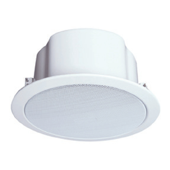
Ceiling speaker, 10 W | C531/10-EN | Type A
PASO S.p.A Via Settembrini, 34
20045 Lainate (MI) - ITALY
Leggere attentamente il presente foglio istruzioni. PASO S.p.A
IT
declina ogni responsabilità per danni a persone e/o cose derivanti
dalla non corretta installazione e dall'uso improprio del prodotto.
La messa in opera del diffusore deve sempre essere effettuata da
personale addestrato: un'errata installazione potrebbe comportare
il rischio di scossa elettrica. Questo diffusore è stato appositamente
sviluppato per essere impiegato in sistemi d'emergenza e d'evacuazione
(VES): viene garantita la salvaguardia della linea di collegamento
altoparlanti nel caso in cui un possibile incendio metta fuori uso uno o più
diffusori ad essa collegati.
DESCRIZIONE
La plafoniera C531/10-EN - caratterizzata da un altoparlante a larga banda
(cono da 8") e da un trasformatore per linee a tensione costante che consente
di regolarne la potenza - fornisce un'ottima resa sonora. Altra peculiarità è la
calotta di protezione in metallo leggero, che consente di contenere il peso
del diffusore (inferiore ai 2 kg). È dotata di un morsetto ceramico e di un
fusibile termico integrato protetto; il grado di protezione IP 21C ne garantisce
la resistenza all'influenza degli agenti atmosferici. Il design piatto e la sua
ridotta profondità la rendono particolarmente adatta per la posa ad incasso
in controsoffitto ove lo spazio a disposizione per l'installazione è minimo.
Ideale per l'installazione in scuole, uffici, hotel e aeroporti.
ISTRUZIONI DI MONTAGGIO
Dopo aver effettuato il foro nel controsoffitto (vedere indicazioni riportate
in ultima pagina), operare come segue:
1) Svitare le viti che fissano la calotta metallica
al corpo della plafoniera.
2) Rimuovere la calotta dalla plafoniera.
3) Far passare il cavo proveniente dalla
linea di distribuzione attraverso i fori sulla
calotta e collegarlo al morsetto ceramico
impostando quindi la potenza d'uscita
desiderata.
Nota: si raccomanda di isolare i terminali
non utilizzati.
4) Riposizionare la calotta sulla plafoniera
e fissarla nuovamente utilizzando le viti
precedentemente rimosse.
5) Inserire la plafoniera all'interno del foro
nel controsoffitto tenendo dritti i due ganci
a molla laterali e portarla a battuta col
controsoffitto.
Frequency response @ 1W/1m
Plafoniera 10W EN54
EN54 10W Ceiling speaker
Please read this instruction sheet carefully. PASO S.p.A.
EN
will accept no liability for personal injury and/or damage to
property resulting from incorrect installation or improper use of
the product. The speaker unit must be set up by trained personnel.
Incorrect installation could result in the risk of electric shocks. These
speaker units have been developed specifically for use in emergency
and evacuation systems (VES): this ensures the protection of the line
connecting the loudspeakers if a fire puts one or more of the speaker units
connected to it out of use.
DESCRIPTION
The C531/10-EN ceiling speaker - featuring a broadband loudspeaker
(8" cone) and a transformer for 100V constant voltage lines which allows
power to be adjusted - provides a very good sound performance. Another
peculiarity is the protective cap in light metal, which allows the weight of
the speaker to be contained (less than 2 kg). It features a ceramic terminal
and a protected integrated thermal fuse; the IP 21C degree of protection
guarantees its resistance to the influence of atmospheric agents. The flat
design and its reduced depth make it particularly suitable for recessed
installation in false ceilings where the space available is minimal. Ideal for
applications in schools, offices, hotels, hospitals and airports.
MOUNTING INSTRUCTIONS
After making the hole in the false ceiling (dimension of the hole has been
shown of last page) and proceed as follows:
1) Undo the screws that fix the metal cap to the
body of the ceiling speaker.
2) Remove the metal cap from the speaker.
3) Pass the cable coming from the 100V
speaker line through the holes on the cap
and connect it to the ceramic terminal
thus setting the desired output power (see
figure).
Note: It is recommended to insulate unused
terminals.
4) Reposition the metal cap on the ceiling
speaker and fix it again using the screws
previously removed.
5) Insert the ceiling speaker inside the hole
in the false ceiling keeping the two lateral
spring hooks straight and bring it up to the
limit with the false ceiling.
C531/10-EN
EN54
EN54
16
24
EN54
EN54
24
16
Advertisement

Subscribe to Our Youtube Channel
Related Manuals for Paso C531/10-EN


Summary of Contents for Paso C531/10-EN
- Page 1 DESCRIZIONE DESCRIPTION La plafoniera C531/10-EN - caratterizzata da un altoparlante a larga banda The C531/10-EN ceiling speaker - featuring a broadband loudspeaker (cono da 8”) e da un trasformatore per linee a tensione costante che consente (8”...
- Page 2 1,6 kg Net weight Nel continuo intento di migliorare i propri prodotti, la PASO S.p.A. si riserva il diritto di apportare PASO S.p.A. strive to improve their products continuously, and therefore reserve the right to make modifiche ai disegni e alle caratteristiche tecniche in qualsiasi momento e senza alcun preavviso.
Need help?
Do you have a question about the C531/10-EN and is the answer not in the manual?
Questions and answers