Table of Contents
Advertisement
Quick Links
Advertisement
Table of Contents

Related Manuals for Lochinvar Herald HCB-117


Summary of Contents for Lochinvar Herald HCB-117
- Page 1 Herald Service Manual Models: HCB-117 HCB-190 HCB-237 HCB-295 Warning: Read and fully understand this manual before attempting to work on this Appliance. It can cause personal injury and damage to the appliance when you do not read the manual and/or do not obey the instructions.
- Page 2 Article Language Version Updated Herald appliance Service English Launch manual OCUMENT IDENTIFICATION Page 1 of 56...
- Page 3 Warranty) for the warranty provisions. IABILITY Service engineer Lochinvar accepts no liability when the Appliance is not used correctly and requires the engineer to: • Read this manual carefully and obey the instructions. • Make sure that the entire Appliance installation complies with all applicable regulations.
- Page 4 OMPLIANCE To safely produce low temperature hot water, the design and construction of the appliance is in accordance with: • UK and European Regulations 2016/426 on appliances burning gaseous fuels (GAR). • UK and European Standard for Gas–fired boilers (BS EN15502). •...
- Page 5 ABOUT THIS MANUAL COPE This manual gives information about safe and correct use of the Appliance and how maintenance and service activities must be done correctly. You must obey the instructions in this manual. Caution Read this manual carefully before you start servicing the appliance. It can cause personal injury and damage to the unit when you do not read the manual and/or do not obey the instructions.
-
Page 6: Safety Guidelines
• Do not re-enter the building until it is safe to do so. Lochinvar Limited is not liable for any damage caused by inaccurately following these instructions. Only original parts may be used when carrying out any repair or service work. -
Page 7: Table Of Contents
CONTENTS SAFETY GUIDELINES ........................5 WHAT TO DO IF YOU SMELL GAS ....................5 DISPLAY PANEL MENU ACCESS ....................7 GENERAL OPERATION ......................... 8 How the control module operates ..................8 Sequence of operation ......................8 Adjust set point temperature(s) ..................... 8 Installer password ........................ -
Page 8: Display Panel Menu Access
HW Tank Temperature. •E-The Navigation Section is located down the left side of the screen. There are five (5) sections located below the Lochinvar icon: Home, View, Setup, Information (About), and Settings. The Home Section is the screen shown in Figure 1. -
Page 9: General Operation
GENERAL OPERATION The appliance uses an advanced stainless steel heat exchanger and an electronic control module that allows fully condensing operation. The fan pulls in gas and air and pushes products of combustion out of the appliance through the heat exchanger and flue system. - Page 10 ABLE EQUENCE OF PERATION Operation 1. Upon a call for heat, the gas pressure switch(es) must be closed. 2. Once the gas pressure switch(es) are closed, the control turns on the appropriate pumps (system and appliance pumps for heating, DHW pump for DHW). The flow switch and/or LWCO must close.
- Page 11 ABLE PARAMETER TABLE This table lists SMART TOUCH control module parameters and where to access them. User Access Installer Access Menu Description Display Modify Display Modify Time and Date Software Version (Read Only) Temperature Units (°C/°F) SH Night Setback Offset SH Night Setback On Times SH Night Setback Off Times DHW Night Setback Offset...
- Page 12 Table 2 continued User Access Installer Access Menu Description Display Modify Display Modify Outdoor 1 Low Outdoor 1 High Set Point 1 at Low Outdoor Temp 1 Set Point 1 at High Outdoor Temp 1 Outdoor Air Shutdown SH1 Outdoor Air Shutdown Differential SH1 Shift Reset Curve SH1 Outdoor 2 Low Outdoor 2 High...
- Page 13 Table 2 continued User Access Installer Access Menu Description Display Modify Display Modify Controlling Sensor BMS Tstat Input ModBus ModBus T/O Cascade Address Cascade Type Max Cascade Set Point Cascade Offset Cascade Differential Min On/Off Time Min Next On Time Boiler Size System Pump Delay Boiler Pump Delay...
-
Page 14: Initial Setup
OW TO SET CLOCK AND DATE Use the following procedure to set the clock: 1. Press the SETTINGS button under the Lochinvar Logo. (see figure 1) 2. Press the SET button across from the date and time. 3. Proceed to set the date and time. -
Page 15: Viewable And Changeable Control Parameters
IEWABLE AND CHANGEABLE CONTROL PARAMETERS Note: Before changing parameters, note the setting so that the unit can be returned to its original operating parameters EATING AND NIGHT SETBACK OFFSET Once the appliance internal clock has been set correctly, the night setback feature can be used to program a lower set point during unoccupied times. -
Page 16: Temperature Settings
EMPERATURE ETTINGS (SH1, SH2, SH3) S EATING OINT IGURE TEMPERATURE SET POINTS There are 3 individual user set points for better zone control. The set points are listed as SH1 set point through to SH3 set point. If multiple set points are calling for heat the highest set point has priority. -
Page 17: Data Logging
OGGING Reset Log Errors The reset log errors function clears the last 10 errors log. UNCTIONS ERVICE ELAY By accessing the Service Maintenance screen from the settings menu, the control can be placed in Service Mode. This will override all other heat demands. The service mode allows the installer to set the unit to any firing rate for the purpose of combustion analysis. - Page 18 OINT IFFERENTIAL When a tank sensor is installed, the tank temperature must drop this amount below the tank set point (DHW Tank Set Point Parameter) before the unit turns back on. The installer can adjust this setting by accessing the Tank Set Point Differential Parameter. The minimum setting is 0°C and the maximum is 22°C.
-
Page 19: Outdoor Reset
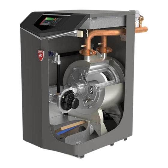
UTDOOR ESET The option of controlling up to three different outdoor resets for low outdoor temperatures is available. (1-3) L UTDOOR When the outdoor air temperature drops to this point, the water temperature will be at the Set Point 1 at Low outdoor Temp 1, Set point 2 at Low Outdoor Temp 2 and Set Point 3 at Low Outdoor Temp 3 parameters. - Page 20 IGURE UTDOOR ESET URVE (SH1 – SH3) UTDOOR HUTDOWN IFFERENTIAL The outdoor air shutdown differential parameter is the number of degrees below Outdoor Air Shutdown SH1, SH2, and SH3 parameters the outdoor air temperature must go before the appliance will respond to a SH demand. These parameters can be changed by the installer by accessing the Outdoor Air Shutdown Differential SH1, SH2, and SH3 parameters.
-
Page 21: Anti-Cycling
OOST The boost time parameter sets the amount of time that must elapse with a SH demand before the water temperature calculated set point will be increased. This parameter can be changed by the installer by accessing the Boost Time Parameter. The time range for this parameter is 0 minutes to 50 minutes. -
Page 22: Control Modes
ETTINGS The Smart Touch control can be programmed to limit the firing rate for a fixed period of time at the start of a heating demand. There are six possible limits, each with their own time delay. The first limit applies as soon as the burner starts. Once its time delay expires, the second limit is applied, and its timer begins. -
Page 23: Cascade Control
The set point or modulation of the unit may be controlled through the 0-10v BMS input or through Modbus. When the BMS parameter is set to INACTIVE, the 0-10v input will be ignored. When set to ACTIVE, the set point or modulation will be controlled by the voltage on the 0-10v input (in the case of 0-10v BMS control) or the 0-10v input value received through Modbus. - Page 24 AXIMUM ASCADE OINT This parameter determines the set point used by the individual units in a Cascade when a system sensor is connected to the Leader unit. When a unit is commanded to fire by the Leader unit, it will attempt to achieve this temperature at its outlet. The Leader unit will limit the modulation of the last unit to fire to hold the temperature at the system supply sensor to the user set point.
- Page 25 IGURE ASCADE EADER ETUP IGURE ASCADE EMBER ETUP CREEN Page 24 of 56...
-
Page 26: Circulation Pumps
INIMUM To prevent units in a Cascade from short cycling, this parameter defines the minimum ON and OFF time for each unit. The installer can adjust this time by accessing the Minimum On/ Off Time parameter. The minimum setting is 0 seconds, and the maximum setting is 10 minutes. -
Page 27: Bms
YSTEM The system pump can be programmed to operate in response to any of the Room Thermostat inputs, or to run continuously until the appliance goes into Outdoor Shutdown. To program the system pump to operate only with a space heating call for heat, set the System Pump Type parameter to CFH. - Page 28 ATE AT AXIMUM OLTS When programmed for BMS control through the 0 - 10V BMS input or through Modbus and the BMS Type is programmed as POWER, the modulation percentage represented by the Volts at Maximum parameter is set by the Rate at Maximum Volts parameter. The minimum value is the Rate at Minimum Volts setting and the maximum is 100%.
- Page 29 (This table lists control module parameters, use the sub- ABLE ERVICE OTIFICATION tab under the Setup tab to access them) AINTENANCE OTICE ONTHS When the appliance control determines that a scheduled service is due based on the months of installation, the appliance display will turn yellow, and a new status screen will appear informing the installer that maintenance is required.
-
Page 30: Maintenance
MAINTENANCE ERVICE AND AINTENANCE CHEDULES ABLE SERVICE SCHEDULE Service Technician (See the following pages for instructions) · Address reported problems · Inspect interior, clean and vacuum if necessary · Clean condensate trap and fill with fresh water · Check for leaks (water, gas, flue, condensate) ·... - Page 31 Warning: Follow the service and maintenance procedures given throughout this manual and in literature shipped with the unit. Failure to perform the service and maintenance could result in damage to the unit, system and may result in serve personal injury, death, or substantial property damage.
- Page 32 trap when there is no condensate present, resulting in an unsafe environment. It is important to check and make sure the ball is still located in the trap, acting as a seal against the flue gases at least once annually and after every cleaning.
- Page 33 HECK ALL PIPING FOR LEAKS Eliminate all system or appliance leaks. Continual fresh makeup water will reduce appliance life. Minerals can build up in sections, reducing heat transfer, overheating heat exchanger, and causing heat exchanger failure. Leaking water may also cause severe property damage.
- Page 34 HECK APPLIANCE RELIEF VALVE 1. Inspect the relief valve and lift the lever to verify flow. Before operating any relief valve, ensure that it is popped with its discharge in a safe area to avoid severe scald potential. 2. After following the above warning directions, if the relief valve weeps or will not seat properly, replace the relief valve.
- Page 35 IGURE REMOVING DOOR HECK FLAME SIGNAL 1. At high fire the flame signal shown on the display should be at least 10 microamps. 2. A lower flame signal may indicate a fouled or damaged flame sense electrode. Cleaning of the electrode may improve this. If the ground wiring is in good condition, and ground continuity is satisfactory, then the electrode will need replacing.
- Page 36 Rope Gasket Note: The rope gasket is intended for sealing combustion. If damaged DO NOT reuse, the rope gasket must be replaced. Contact Lochinvar for a replacement. EST LOW WATER FLOW CONDITIONS Test procedure 1. Place the unit into service mode.
-
Page 37: Troubleshooting
TROUBLESHOOTING Warning: Label all wires prior to disconnection when servicing controls. Wiring errors can cause improper and dangerous operation. Always disconnect power to the unit before servicing. Failure to comply could result in severe personal injury, death, or property damage. EFORE TROUBLESHOOTING 1. - Page 38 ABLE ROUBLESHOOTING HART FAULT CAUSE CORRECTIVE ACTION • Check external line switch, fuse, or breaker. • Check position of ON/OFF switch. Turn switch to the ON position. • Check 230 vac through the No 230 VAC supplied to unit. ON/OFF switch. •...
- Page 39 HECKING TEMPERATURE SENSORS The unit temperature sensors (inlet water, outlet water, system water, flue, and outdoor air) are all resistance type devices. The following tables show the correct values for the sensors at various temperatures. Use an ohm meter to read the resistance of the sensor at a known temperature.
- Page 40 – N ABLE ROUBLESHOOTING OISY YSTEM FAULT CAUSE CORRECTIVE ACTION Supply gas problem. • Refer to the Gas Connections section of the Natural gas pressures Installation and Operation Manual for detailed should be between information concerning the gas supply. 17.5 and 20mbar •...
- Page 41 – F ABLE ROUBLESHOOTING AULT ESSAGES ISPLAY ON NTERFACE FAULT DESCRIPTION CORRECTIVE ACTION • Reset the pressure switches. • Measure the supply gas pressure to determine cause of failure. Natural gas pressures should be between 17.5 and 20mbar - Either the optional •...
- Page 42 – C ABLE ROUBLESHOOTING ONTINUED FROM PREVIOUS PAGE FAULT DESCRIPTION CORRECTIVE ACTION • Check the wiring connections to switch. Wires should be connected to the common and normally closed terminals. • Air intake lengths exceed the maximum allowed lengths. Check flue guidance in ICM instructions.
- Page 43 – C ABLE ROUBLESHOOTING ONTINUED FROM PREVIOUS PAGE FAULT DESCRIPTION CORRECTIVE ACTION • Check wiring harness connection at the gas valve and at the main control board. • Inspect spark electrode and associated wiring for damage and connection. Reference this manual for removal and cleaning procedures.
- Page 44 17 T – C ABLE ROUBLESHOOTING ONTINUED FROM PREVIOUS PAGE FAULT DESCRIPTION CORRECTIVE ACTION Flame Sequence (will require a • Check supply voltage for proper polarity. manual reset once • Check external wiring for voltage feedback. the condition has The flame detector circuit •...
- Page 45 – C ABLE ROUBLESHOOTING ONTINUED FROM PREVIOUS PAGE FAULT DESCRIPTION CORRECTIVE ACTION Verify that the system is full of water and that all air has been properly purged from the system. • Verify that the water heater is piped correctly between water heater and buffer vessel.
- Page 46 – C ABLE ROUBLESHOOTING HART ONTINUED FROM PREVIOUS PAGE FAULT DESCRIPTION CORRECTIVE ACTION Sensor Shorted Check the sensors and their associated wiring. Either the inlet (Will require a manual Repair or replace the sensor or wiring if water or outlet reset once the condition has damaged.
- Page 47 – C ABLE ROUBLESHOOTING HART ONTINUED FROM PREVIOUS PAGE FAULT DESCRIPTION CORRECTIVE ACTION • Verify that the system is full of water and that all air has been properly purged from the system. • Verify that the water heater is piped properly between the water heater and buffer vessel.
- Page 48 – C ABLE ROUBLESHOOTING HART ONTINUED FROM PREVIOUS PAGE FAULT DESCRIPTION CORRECTIVE ACTION The main control board Watch Dog Error • Replace the main control board. has detected an internal fault. The main control board Write EEProm • Replace the main control board. has detected an internal fault.
- Page 49 HECK FLAME AND COMBUSTION 1. Turn the main power off to the unit by placing the “On/Off switch in the off position. 2. Remove the flue temperature sensor from the flue pipe connection. Combustion measurements will made at this point. 3.
- Page 50 AS VALVE ADJUSTMENT PROCEDURE 1. For HCB117: Remove the front panel from the unit. For HCB190, 235, 295: Remove the top access cover from the unit. 2. For HCB190, 235, 295: Remove the cover on top of the gas valve. 3.
-
Page 51: Appendix 1 Control Inputs
APPENDIX 1 CONTROL INPUTS Page 50 of 56... -
Page 52: Appendix 2 Control Outputs
APPENDIX 2 CONTROL OUTPUTS Page 51 of 56... -
Page 53: Appendix 3 Spare Parts Finder
APPENDIX 3 SPARE PARTS FINDER Item No Description of item Item Comments HCB117CE HCB190CE HCB235CE HCB295CE Heat Exchanger LL100330273 LL100330275 LL100330276 LL100330277 Low Voltage Connection Board Prior Serial #2148 LL100208459 Low Voltage Connection Board Beg Serial #2148 LL100351933 Main Control Board LL100330278 LL100334033 LL100334034 LL100334035 Display Assembly LL100330279... - Page 54 Water Pipe Coupling LL100330232 Condensate Trap Assembly LL100330233 Condensate Trap Hose LL100330234 Outdoor Sensor LL100208834 Spark Ignitor Harness LL100330235 Flame Sensor Harness LL100208622 Electrode Ground Harness LL100330236 Communication Cable Harness LL100330237 Air Filter LL100233577 Compression Latch LL100302180 Junction Box Cover LL100335982 Control Cover LL100335985...
- Page 55 Casings and externally sited items Page 54 of 56...
- Page 56 Control boards Heat exchanger and burner Page 55 of 56...
- Page 57 Page 56 of 56...
Need help?
Do you have a question about the Herald HCB-117 and is the answer not in the manual?
Questions and answers