
Related Manuals for Tellabs OLT1


Summary of Contents for Tellabs OLT1
-
Page 1: Tellabs® Olt1 Optical Line Terminal Description, Installation, And Turn Up Guide
Tellabs® OLT1 Optical Line Terminal Description, Installation, and Turn Up Guide Copyright © 2024 Tellabs ® All Rights Reserved... -
Page 2: Tellabs® Information
Information in this publication is subject to change without notice. Trademarks The following trademarks and service marks are owned by Tellabs Operations, Inc. or its affiliates in the United ® ®... -
Page 3: Table Of Contents
This document provides instructions to install the Tellabs® FlexSym XGS-PON Optical Line Terminal 1 (OLT1). The OLT1 is a self-contained and sealed unit, for mounting in standard 23-in (58.4cm) and 19-in (48.3cm) size racks. This guide describes the 100−220 VAC powering, suggested mounting instructions and turn up and the initialization Page 3 of 30 ©... -
Page 4: Description
Tellabs® OLT1 Optical Line Terminal Description, Installation, and Turn Up Guide procedures for the OLT1. The Tellabs® OLT1 has two customer replaceable parts, it has replaceable power modules and a fan tray assembly. DOCUMENT NUMBER ENG-010672 Document Revision History This section describes changes to this document:... - Page 5 Tellabs® OLT1 Optical Line Terminal Description, Installation, and Turn Up Guide The Tellabs OLT1 is packaged and shipped to the customer, ready for installation. Note: Shelf extensions are required if the Tellabs® OLT1 shelf is to be installed in a 23-inch rack and must be ordered separately. ...
- Page 6 4-ports Gigabit Ethernet and 2-ports 10-Gigabit Ethernet network uplink interfaces for flexible network design · options Interworks with all Tellabs ONTs, both closet-based and deep fiber ONTs, including both G-PON and XGS-PON · versions Environmentally-hardened for remote deployments in main data centers, or remote locations, with no air ·...
- Page 7 Tellabs® OLT1 Optical Line Terminal Description, Installation, and Turn Up Guide 10GbE XFPs: Two (2) XFPs · Power Max draw 5.0 A @ 48 VDC · Dual 100/240 VAC · Total input power 240 W · 2nd power supply for redundancy ·...
- Page 8 Tellabs® OLT1 Optical Line Terminal Description, Installation, and Turn Up Guide GPON - Maximum Transmission Unit (MTU) 9216 bytes · XGS-PON - Maximum Transmission Unit (MTU) 1546 bytes · Passive Optical Network Eight (8) PON ports · Up to 64-way optical split ·...
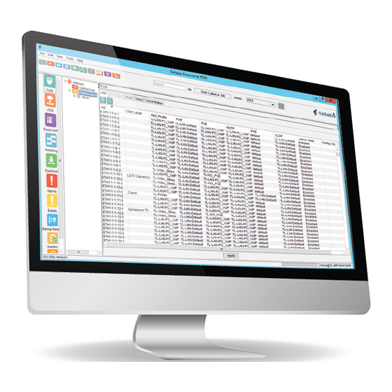
- Page 9 Tellabs® OLT1 Optical Line Terminal Description, Installation, and Turn Up Guide Installation Mounting: 19" or 23" rack options · Alarming: No dry relay contact inputs · Timing: No timing support for fax or modem traffic · Compliance Tellabs Panorama PON Manager ·...
- Page 10 Tellabs® OLT1 Optical Line Terminal Description, Installation, and Turn Up Guide OLT1 LED BEHAVIOR Indications Comments After approximately 7 seconds after inserting the power cable Red Solid the PON CPU STAT illuminates red solid. The PON CPU STAT LED will remain red solid until Initialization.
- Page 11 Tellabs® OLT1 Optical Line Terminal Description, Installation, and Turn Up Guide When the PON Link LED indication is green solid, it indicates that Green Solid all Provisioned ONT serial numbers are ranged on the PON and there are no unexpected ONTs. The state of the PON is good.
-
Page 12: Tellabs Olt1 Site Preparation
Figure 1: 19" Tellabs OLT1 Optical Line Terminal The Tellabs OLT1 is packaged and shipped to the customer, ready for installation. Note: Shelf extensions are required if the Tellabs® OLT1 shelf is to be installed in a 23-inch rack and must be ordered separately. Facility Grounding ·... -
Page 13: Tellabs Olt1 Power Availability
Previous | Next Tellabs OLT1 Power Availability Ensure that there is an available 100/220 VAC outlet within six feet of the Tellabs OLT1 unit. Previous | Next Rack Mounting When selecting the installation rack and its location, the following items should be considered as part of that selection: Elevated Operating Ambient - If installed in a closed or multi-unit rack assembly, the operating ambient... -
Page 14: Install The Tellabs Olt1
Install 2:32 Fiber Splitter · The instructions provided in this section assume all of the components to be installed are being ordered from Tellabs. If any component was not ordered from Tellabs, refer to the installation instructions included with that component. -
Page 15: Install 1:32 Splitter
Note: When inserting the mounting screws ensure the frame ground is installed on the screw before inserting it into the equipment frame. 3. Insert the remaining screws into the mounting holes and tighten as required to ensure the OLT1 shelf is secure. -
Page 16: Tellabs Olt1 Turn Up And Initializaton
Tellabs® OLT1 Optical Line Terminal Description, Installation, and Turn Up Guide 2. Secure the splitter shelf with four #12-24 screws. Inserting the two upper mounting screws first. Do not tighten the mounting screws until Step Three has been completed. Figure 4 shows a typical 2:32 Fiber Splitter shelf. - Page 17 Use the following procedure to verify and connect fiber optic cables between the OLT and the 2:32 fiber Splitter. Note 1: PON Protection Groups can be sourced from; 1) two PON ports on the Tellabs OLT1, or 2) PON ports on different PON cards in different OLTs.
-
Page 18: Power Up The Tellabs Olt1
120/240 VAC outlet or use a 208V/240V outlet to power up the unit, within the European Union. Note: The Tellabs OLT1 does not have a power on/off switch, as it is not intended to power down the shelf while it is in service. -
Page 19: Perform Optic Power Level Testing
Perform Optic Power Level Testing This section provides the instructions for installing and testing the fiber connections using the optic power meter to measure power levels, after the Tellabs OLT1 has been turned up. Refer to Turn Up the Tellabs OLT1. LASER SAFETY Danger! The equipment in the following procedures shall be installed in a restricted access location from the general public. -
Page 20: Turn Up The Tellabs Olt1
8. Verify the optic levels from Table 5 using another quad fiber jumper. If the optic levels are not verified, this may indicate a bad quad fiber jumper or the Tellabs OLT1. Replace the quad fiber jumper, if required. 9. If the Tellabs unit is bad, contact Tellabs Technical Assistance Center (TAC) for assistance. - Page 21 Connect the other end of the cable to the DB-9 connector on your PC/laptop. Open the serial communication software on your PC/laptop. In the configuration screen, use the COM port settings listed in Table 4 to communicate with the Tellabs OLT1. Table 4: COM Port Settings...
- Page 22 Tellabs® OLT1 Optical Line Terminal Description, Installation, and Turn Up Guide Note: The password is not displayed on the screen. 3. After logging in with the admin/tellabs default values, the following is displayed on the screen: Password expired, you must change your password to continue: Enter current password: _ ...
- Page 23 Tellabs® OLT1 Optical Line Terminal Description, Installation, and Turn Up Guide 15. Enter 1, 2, or 3 and press ENTER. The IPv4 configuration and the Network Mask and Gateway configuration is displayed. Press ENTER for each default value. IPV4 Configuration: Address: (IPv4 address) ......[192.168.1.2] : 192.168.1.2 Network Mask: ........[255.255.255.0] : 255.255.255.0 Default Gateway ........[192.168.1.1] : 192.168.1.1...
-
Page 24: Maintenance
The customer will contact the Tellabs® Technical Assistance Center (TAC), if the Tellabs OLT1 becomes inoperable or if there is any damage to the unit after arrival. The Tellabs OLT1 will be boxed and shipped back to Tellabs for maintenance or a new replacement. - Page 25 Figure 6: Fault Light Displays The rectifier should be shipped back to Tellabs® and a new rectifier will be sent to the customer’s site as a replacement. Follow the procedures below to remove the rectifier: Note: The customer will purchase a new rectifier from Tellabs®. Contact the Tellabs Technical Assistance Center (TAC), for instructions.
- Page 26 5. Loosen the right and left screws that hold the rectifier retractable handles in position. Figure 7: Retractable Handles 6. Remove the rectifier from the slot. 7. If the rectifier is not going to be shipped back to Tellabs, dispose of the rectifier ac- cording to local practices or regulations. Install the AC-DC Rectifier When the customer receives a replacement rectifier, follow these procedures to install the new rectifier into the Tellabs OLT1.
- Page 27 12. Using the Phillips screwdriver, tighten the two screws (one on each side) to hold the handles in the locked position. 13. Locate the rectifier cover plate on the left side of the OLT1 faceplate. 14. Replace the rectifier cover plate.
-
Page 28: Contacting Technical Support
Contacting Technical Support TELLABS TECHNICAL ASSISTANCE CENTER Tellabs TAC is available 24x7x365. Our team is comprised of Support Engineers with years of telecommunications and networking experience, holding a variety of networking certifications in addition to the Tellabs Certification for the product(s) they support. - Page 29 Tellabs® OLT1 Optical Line Terminal Description, Installation, and Turn Up Guide Previous | Top Page 29 of 30 © 2024 Tellabs Enterprise, Inc. All rights reserved.
- Page 30 Tellabs® OLT1 Optical Line Terminal Description, Installation, and Turn Up Guide Page 30 of 30 © 2024 Tellabs Enterprise, Inc. All rights reserved.
Need help?
Do you have a question about the OLT1 and is the answer not in the manual?
Questions and answers