Sign In
Upload
Download
Table of Contents
Contents
Add to my manuals
Delete from my manuals
Share
URL of this page:
HTML Link:
Bookmark this page
Add
Manual will be automatically added to "My Manuals"
Print this page
×
Bookmark added
×
Added to my manuals
Manuals
Brands
Tellabs Manuals
Switch
7300 Series
System manual
Tellabs 7300 Series System Manual
Metro ethernet switching ethernet aggregation switch ethernet edge switch
Hide thumbs
1
2
Table Of Contents
3
4
5
6
7
8
9
10
11
12
13
14
15
16
17
18
19
20
21
22
23
24
25
26
27
28
29
30
31
32
33
34
35
36
37
38
39
40
41
42
43
44
45
46
47
48
49
50
51
52
53
54
55
56
57
58
59
60
61
62
63
64
65
66
67
68
69
70
71
72
73
74
75
76
77
78
79
80
81
82
83
84
85
86
87
88
89
90
91
92
93
94
95
96
97
98
99
100
101
102
103
104
105
106
107
108
109
110
111
112
113
114
115
116
117
118
119
120
121
122
123
124
125
126
127
128
129
130
131
132
133
134
page
of
134
Go
/
134
Contents
Table of Contents
Troubleshooting
Bookmarks
Table of Contents
Table of Contents
Introduction
Reason for Issue
Conventions Used in this Manual
Performing Numbered Steps
System Overview, Features, and Specifications
Tellabs 7345 Ethernet Aggregation Switch Overview
Tellabs 7325 Ethernet Edge Switch Overview
General System Features
Class of Service
Operations, Administration and Maintenance Capabilities
Craft Station
System Administration
Features Introduced in FP1.1
Platform Applications
Specifications
System Dimensions
Power Requirements
Environmental Specifications
Rohs and WEEE Compliance
System Architecture
Switched Ethernet Services and Features
Quality of Service (Qos)
Qos Services
Overview of Qos Operations
Ethernet Service Support
Trtcm
Ethernet Interface Support
Ethernet Packet Support
System Scalability
System Redundancy (Tellabs 7345 Switch)
Power Supplies
Fans
Redundancy (Tellabs 7325 Switch)
802.1D - MAC Bridging and Spanning Tree
VLAN Support
Traffic Management and Qos
Link Aggregation (802.3Ad)
Ethernet OAM Support
Maintenance Domain (MD)
Maintenance Association (MA)
Local/Remote System Management
System Components
Tellabs 7345 Switch System Configuration and Basic Components
Hardware Components
Tellabs 7345 Shelf
10G Switch Module
Front Panel Leds
10G Switch Module Physical Specifications
Central Management Controller Card (CMCC) Module
Front Panel Leds
CMCC Physical Specifications
Power Supply Unit (PSU)
Front Panel Leds
Power Supply Unit Physical Specifications
Fan Tray with Filter
Front Panel Leds
Fan Tray Physical Specifications
Tellabs 7325 Switch Configuration and Basic Components
Power Supply Unit (PSU)
Front Panel Leds
Power Supply Unit Physical Specifications
Small Form-Factor Pluggables (Sfps/Xfps)
SFP/XFP Physical Specifications
Optional Equipment
7300 Extended Temp AC-DC Power Converter
Fuse Panel
Installation
Preparation of the Installation Site
Cooling Requirements
Environmental Requirements
Electrostatic Discharge (ESD) Precautions
Fiber Optic Safety
Laser Radiation Exposure
Optical Fiber Handling
Unpacking the Tellabs 7300 NE Components
Accessories
Physical Placement
Installing the Tellabs 7300 Shelf
Installing the Fuse Panel (Optional)
Connecting the Fuse Panel to the BDFB
Installing the Tellabs 7300 Power Converter Tray (Optional)
Install the Power Converter in the Power Converter Tray
Install the Assembled Power Converter Tray in the Rack
Grounding the Tellabs 7300 Shelf
Installing the Modules (Tellabs 7345 Switch Only)
Installing the Modules (Tellabs 7325 Switch Only)
Tellabs 7325 Switch
Connecting DC Power to the Tellabs 7300 NE
PSU Redundancy Options (Tellabs 7345 Switch Only)
Installing the Transceivers
Transceiver Installation (Tellabs 7345 Switch)
Transceiver Installation (Tellabs 7325 Switch)
Connecting the Cables to the 10G Switch Module in the Tellabs 7345 Switch
RJ-45 Electrical SFP Pinouts
Tellabs 7345 Switch
Tellabs 7325 Switch
Alarm Wiring
Initializing the Tellabs 7300 NE
One Power Supply Installed
Set System Time and Date Manually
Change System Time and Date
Enable Daylight Savings Time
Save Configuration
Synchronize System Time and Date Via SNTP
Set up Simple Network Time Protocol (SNTP)
Create New Users
Configure RADIUS
Enternal Alarm Input (Optional)
Activate SNMP Traps for ENV Alarms
Deactivate SNMP Traps for ENV Alarms
External Contact Output (Optional)
Maintenance
Back up the Database to Flash
Back up the Database to a Remote Server
Schedule a Local Backup
Restore a Local Backup
Restore a Remote Backup
Upgrade the System Software
Replace Modules
Module Replacement Pre-Checklist
Replacing a CMCC Module (Tellabs 7345 Switch Only)
Replacing a PSU Module
Replacing a 10G Switch Module (Tellabs 7345 Switch Only)
Replacing a Fan Tray (Tellabs 7345 Switch Only)
Managing Fan Filter Maintenance (Tellabs 7345 Switch Only)
Removing the Fan Filter
Replacing the Fan Filter
Safety Precautions
Optical Fiber Handling
Fiber Optic Cleaning Requirements
Tools
Materials
Fiber Optic Cleaning Procedures
Cleaning SC Connectors
Cleaning LC Connectors
Troubleshooting
Tellabs Customer Service
Module Replacement
Performance Symptoms
Symptoms and Recommended Actions
After-Sale Technical Support
Additional Information
Module Repair and Return
General Repair and Return Information
Contacting Tellabs Repair Centers
Appendix A Glossary
Advertisement
Quick Links
1
Tellabs 7345 Ethernet Aggregation Switch Overview
2
Craft Station
Download this manual
System Manual
76.7300FP11/2
®
Tellabs
7300 Metro Ethernet Switching Series
®
Tellabs
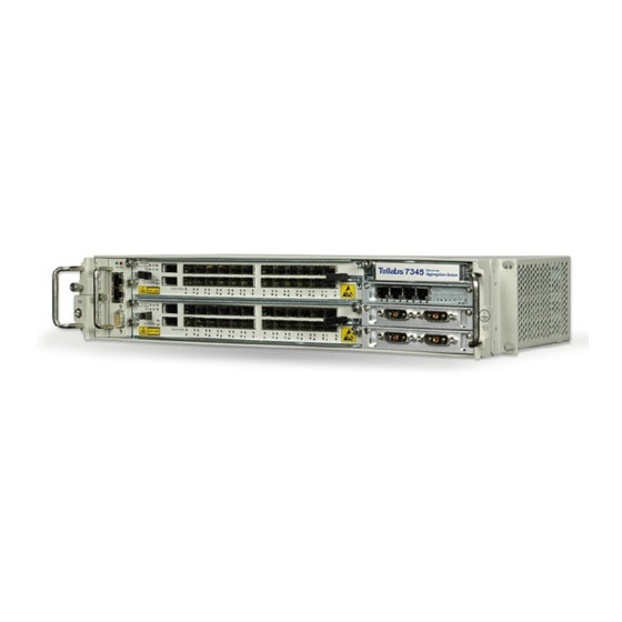
7345 Ethernet Aggregation Switch
®
Tellabs
7325 Ethernet Edge Switch
Revision A, 8/09
Copyright © 2009 Tellabs. All rights reserved.
®
Table of
Contents
Previous
Page
Next
Page
1
2
3
4
5
Advertisement
Table of Contents
Need help?
Do you have a question about the 7300 Series and is the answer not in the manual?
Ask a question
Questions and answers
Related Manuals for Tellabs 7300 Series
Switch Tellabs 7345 System Manual
Metro ethernet switching ethernet aggregation switch ethernet edge switch (134 pages)
Switch Tellabs 7325 System Manual
Metro ethernet switching ethernet aggregation switch ethernet edge switch (134 pages)
Switch Tellabs 6325 Hardware Installation Manual
6300 managed transport system edge node (80 pages)
Switch Tellabs ONT248 Installation And Manual
(29 pages)
Switch Tellabs OLT1 Installation Manual
(30 pages)
Switch Tellabs FlexSym BOLT OLT Installation Manual
(21 pages)
This manual is also suitable for:
7345
7325
Table of Contents
Print
Rename the bookmark
Delete bookmark?
Delete from my manuals?
Login
Sign In
OR
Sign in with Facebook
Sign in with Google
Upload manual
Upload from disk
Upload from URL


Need help?
Do you have a question about the 7300 Series and is the answer not in the manual?
Questions and answers