Table of Contents
Advertisement
Quick Links
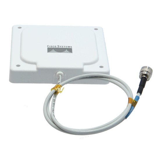
Cisco Aironet 9.5-dBi Patch Antenna
(AIR-ANT5195P-R)
This document outlines the specifications, describes the AIR-ANT5195P-R 9.5-dBi patch antenna, and
provides instructions for mounting it. The antenna operates in the 5-GHz frequency range and is
designed for use in both indoor and outdoor environments.
The following information is provided in this document.
Technical Specifications, page 2
•
System Requirements, page 3
•
Installation Guidelines, page 4
•
Installing the Antenna, page 5
•
Obtaining Documentation and Submitting a Service Request, page 11
•
Corporate Headquarters:
Cisco Systems, Inc., 170 West Tasman Drive, San Jose, CA 95134-1706 USA
Copyright © 2005 Cisco Systems, Inc. All rights reserved.
Advertisement
Table of Contents

Related Manuals for Cisco AIR-ANT5195P-R - Aironet Antenna


Summary of Contents for Cisco AIR-ANT5195P-R - Aironet Antenna
- Page 1 (AIR-ANT5195P-R) This document outlines the specifications, describes the AIR-ANT5195P-R 9.5-dBi patch antenna, and provides instructions for mounting it. The antenna operates in the 5-GHz frequency range and is designed for use in both indoor and outdoor environments. The following information is provided in this document.
-
Page 2: Technical Specifications
5.1 in. (12.9 cm) Width 5.1 in. (12.9 cm) Height 1.0 in. (2.5 cm) Weight 10 oz. (0.2 kg) Operating temperature range –22°F to 158°F (–30°C to 70°C) Storage temperature range –40°F to 185°F (–40°C to 85°C) E-Plane Pattern H-Plane Pattern Cisco Aironet 9.5-dBi Patch Antenna (AIR-ANT5195P-R) -
Page 3: System Requirements
System Requirements System Requirements This antenna is designed for use with Cisco Aironet access points and bridges but can be used with any 5-GHz Cisco Aironet radio device that uses an RP-TNC connector. Safety Precautions Installation of this antenna near power lines is dangerous. For your safety, follow the installation Warning directions. -
Page 4: Installation Guidelines
Each person should be assigned to a specific task, and should know what to do and when to do it. One person should be in charge of the operation to issue instructions and watch for signs of trouble. -
Page 5: Site Selection
Generally, the higher an antenna is above the ground, the better it performs. Good practice is to install your antenna about 5 to 10 ft (1.5 to 3 m) above the roof line and away from all power lines and obstructions. - Page 6 Use the antenna as a template to mark the locations of the four mounting holes with a pencil. Step 2 Use a drill and 3/16-in. (4.8 mm) drill bit to drill four holes at the locations you marked in Step 2. Step 3 Start a plastic anchor into each hole.
-
Page 7: Mounting On A Mast
Place one ¼-20 u-bolt around the mast, and place one support bracket on the u-bolt. Place the mounting plate on the u-bolt. Step 2 Place two ¼-inch flat washers and ¼-20 nuts on the ends of the u-bolt. Tighten the nuts finger tight. Step 3 Repeat steps 1 through 3 for the other u-bolt. - Page 8 Install the screws through the antenna mounting plate and install the #8 nuts. Step 8 Tighten the #8 screws and nuts with a #2 Phillips screwdriver and an 11/32-in. (9-mm) wrench. Step 9 Do not overtighten the nuts. You could damage the antenna.
- Page 9 The antenna can also be mounted on an optional articulated mounting device as shown in Figure 2. The articulated mount is used with the mast mount to provide a way to adjust the antenna elevation and azimuth through a limited range. Figure 2...
-
Page 10: Antenna Cable Information
If you install additional lengths of antenna cable, be sure to install a suitable strain relief. The antenna Caution may be damaged if you do not eliminate the extra weight of the cable. The antenna is not designed to support the weight of a cable longer than the installed 3-ft (91.4 cm) cable. -
Page 11: Grounding The Antenna
Grounding the Antenna Follow these steps to ground the antenna in accordance with national electrical code instructions. Use No. 10 AWG copper or No. 8 or larger copper-clad steel or bronze wire as ground wires for both Step 1 mast and lead-in. Securely clamp the wire to the bottom of the mast. - Page 12 Cisco and the Cisco Logo are trademarks of Cisco Systems, Inc. and/or its affiliates in the U.S. and other countries. A listing of Cisco's trademarks can be found at www.cisco.com/go/trademarks. Third party trademarks mentioned are the property of their respective owners. The use of the word partner does not imply a partnership relationship between Cisco and any other company.
Need help?
Do you have a question about the AIR-ANT5195P-R - Aironet Antenna and is the answer not in the manual?
Questions and answers