Table of Contents
Advertisement
Quick Links
Advertisement
Table of Contents
Troubleshooting

Subscribe to Our Youtube Channel
Related Manuals for Hiwin D1


Summary of Contents for Hiwin D1
- Page 1 D1 Servo Drive User Manual www.hiwinmikro.tw MD20UE01-2109_V3.0...
- Page 2 , 2021 D1 servo drive Update section 4.2 Wiring for main circuit. Update section 8.3 Brake protection. D1 firmware version 0.250 This user manual is translated from the Chinese or later version user manual D1驅動器使用者操作手冊 (version D1 CoE firmware version Mar.
-
Page 3: Table Of Contents
Wiring diagram for motor over temperature protection ..............4-27 4.8.4 Wiring diagram for Hall sensor ......................4-27 EtherCAT communication (CN4) ......................4-28 4.10 Accessories of D1 servo drive ........................4-29 Servo drive configuration ........................... 5-1 Installation and communication ........................5-2... - Page 4 Configuration center ........................... 5-8 5.2.1 Setting parameters of motor ....................... 5-9 5.2.2 Setting parameters of encoder ......................5-12 5.2.2.1 HIWIN standard encoder ....................... 5-14 5.2.2.2 User-defined encoder setting ......................5-15 5.2.2.3 Setting encoder output ........................5-16 5.2.3 Setting Hall sensor ..........................5-19 5.2.4...
- Page 5 6.7.3 Filter ..............................6-41 6.7.3.1 Low-pass filter ..........................6-42 6.7.3.2 Notch filter ............................. 6-43 6.7.4 Gain tuning ............................6-44 6.7.5 Spectrum analysis ..........................6-45 Checking encoder signal .......................... 6-45 Error map function ............................ 6-47 6.9.1 Setting error map function ......................... 6-48 6.9.2 Enabling error map function ......................
- Page 6 9.4.2 Error description and corrective action ..................... 9-10 Servo drive thermal curve ..........................10-1 10.1 Operating temperature and cooling ......................10-2 10.2 Heat sink..............................10-3 Advanced frequency analysis ........................11-1 11.1 Advanced frequency analysis ........................11-2 11.2 Frequency analyzer ..........................11-3 11.3 SMCL tools ...............................
-
Page 7: About This User Manual
1. About this user manual About this user manual ............................1-1 General precautions ........................... 1-2 Safety precautions ............................1-3 HIWIN MIKROSYSTEM CORP. -
Page 8: General Precautions
HIWIN is not responsible for any damage, accident or injury caused by incorrect power supply. ◆ Ensure the product is used with its rated load. HIWIN is not responsible for any damage, accident or injury caused by improper usage. ◆... -
Page 9: Safety Precautions
MD20UE01-2109 D1 Servo Drive User Manual About This User Manual 1.2 Safety precautions ◼ Carefully read through this user manual before installation, transportation, maintenance and examination. Ensure the product is correctly used. ◼ Carefully read through electromagnetic (EM) information, safety information and related precautions before operation. - Page 10 MD20UE01-2109 About This User Manual D1 Servo Drive User Manual ◆ Do not use the product in location which is subject to humidity, corrosive materials, flammable gas or flammable materials. ◆ Storage ◆ Do not store the product in location which is subject to water, water drop, direct sunlight, harmful gas or liquid.
- Page 11 ◆ Set external wiring for emergency stop to stop the motor at any time. ◆ Maintenance ◆ Do not disassemble or modify the product. ◆ Do not repair the product by yourself, please contact HIWIN for repair. HIWIN MIKROSYSTEM CORP.
- Page 12 MD20UE01-2109 About This User Manual D1 Servo Drive User Manual (This page is intentionally left blank.) HIWIN MIKROSYSTEM CORP.
- Page 13 2. Specifications Specifications ..............................2-1 Safety certificates and model explanations ....................2-2 2.1.1 Safety certificates ..........................2-2 2.1.2 Model explanation ..........................2-3 Basic specifications ............................ 2-4 Dimensions ..............................2-8 Installation ..............................2-10 System requirement ..........................2-11 HIWIN MIKROSYSTEM CORP.
-
Page 14: Specifications
MD20UE01-2109 Specifications D1 Servo Drive User Manual 2.1 Safety certificates and model explanations 2.1.1 Safety certificates D1 servo drive complies with the following safety standards. ◼ CE compliance Table2.1.1.1 EN61800-3: 2004 (Category C3) EN61000-3-2: 2006/A1: 2009/A2: 2009 EN61000-3-3: 2008 EN61000-6-2: 2005... -
Page 15: Model Explanation
MD20UE01-2109 D1 Servo Drive User Manual Specifications 2.1.2 Model explanation The model explanation of D1 servo drive is provided as below. Column Example Product Name D1…………………= D1 Rated Output 36 A……………..…………….…………...= 36 Communication Interface Standard format RS232 (No communication interface).…= S EtherCAT (CoE) ………………………………..………..…..= E... -
Page 16: Basic Specifications
MD20UE01-2109 Specifications D1 Servo Drive User Manual 2.2 Basic specifications Table2.2.1 D1-36 Voltage 100 - 240 Vac ±10% Frequency 47 to 63 Hz Input Phase 1 Ø or 3 Ø Power Control Voltage +24 Vdc ±10% Control Current 1 A minimum... - Page 17 MD20UE01-2109 D1 Servo Drive User Manual Specifications Analog Input Command The specification is the same as the one in velocity mode. Force/ torque Digital Input Command The specification is the same as the one in velocity mode. Mode Command Source...
- Page 18 MD20UE01-2109 Specifications D1 Servo Drive User Manual Note: When I9 and I10 are set for digital inputs, they cannot be programmed as general inputs. 0.3 Adc max, +40 Vdc max (Open drain) Digital Output [O1~O3] Brake Output Brake [O4], 1 Adc max.
- Page 19 MD20UE01-2109 D1 Servo Drive User Manual Specifications HIWIN MIKROSYSTEM CORP.
-
Page 20: Dimensions
D1 Servo Drive User Manual 2.3 Dimensions The dimensions and mounting holes of D1 and D1 EtherCAT (CoE and mega-ulink) servo drives are shown in figures 2.3.1 and 2.3.2. The unit is mm. The diameter of the mounting hole is 4 mm. - Page 21 MD20UE01-2109 D1 Servo Drive User Manual Specifications D1-DNN02A Figure2.3.2 D1 EtherCAT servo drive HIWIN MIKROSYSTEM CORP.
-
Page 22: Installation
MD20UE01-2109 Specifications D1 Servo Drive User Manual 2.4 Installation If the servo drive is installed in a control box, ensure it is mounted with conductive screws. The insulating materials, such as paint, on the contact surface of the control box must be removed for grounding the servo drive through the control box. -
Page 23: System Requirement
MD20UE01-2109 D1 Servo Drive User Manual Specifications 50 mm or 20 mm or 20 mm or above above above 50 mm 50 mm above above Control 50 mm or above Figure2.4.2 2.5 System requirement Table2.5.1 1.0 GHz or higher 512 MB or more... - Page 24 MD20UE01-2109 Specifications D1 Servo Drive User Manual (This page is intentionally left blank.) 2-12 HIWIN MIKROSYSTEM CORP.
-
Page 25: Operation Principles
Gain margin and phase margin ........................3-9 3.6.1 Nyquist plot ............................3-9 3.6.2 Bode plot ............................3-12 Move and settling ............................. 3-13 Error compensation ..........................3-14 Velocity ripple ............................3-15 3.10 Enabling..............................3-15 3.11 Basic physical quantities .......................... 3-16 HIWIN MIKROSYSTEM CORP. -
Page 26: Operation Mode
MD20UE01-2109 Operation Principles D1 Servo Drive User Manual 3.1 Operation mode D1 servo drive supports the following operation modes. (1) Position mode (2) Velocity mode (3) Force/torque mode (4) Stand-alone mode Each operation mode will be described in the following sections. -
Page 27: Velocity Mode
MD20UE01-2109 D1 Servo Drive User Manual Operation Principles 3.1.2 Velocity mode In velocity mode, the servo drive receives analog command (V command) from controller. The input voltage range is from -10 V to +10 V. The input voltage is transformed into corresponding velocity command to drive motor. -
Page 28: Stand-Alone Mode
MD20UE01-2109 Operation Principles D1 Servo Drive User Manual (2) Using PWM command PWM command is transformed into current command to control the force and torque of motor. The corresponding current of full PWM can be set in the servo drive. -
Page 29: Analog Type
When buffered encoder output is selected, signals received from encoder are directly sent to controller. Invert function is provided in D1 servo drive. When invert function is selected, the signals received from encoder will be inverted before being sent to controller. -
Page 30: Path Planning
MD20UE01-2109 Operation Principles D1 Servo Drive User Manual Z-phase signal Pulse width 1/2 pulse width *Home position is reached for the first time. Figure3.3.1 Buffered encoder output Encoder Emulated Signal encoder processing output Figure3.3.2 3.4 Path planning Path planning is usually done by controller. The controller calculates suitable motion command based on the required distance, velocity, acceleration and smooth factor. - Page 31 Optical scale or encoder provides the servo drive with the current position of motor. Units used for different motion types are as below. In D1 servo drive, reference position means position command. Reference position is calculated by the path generator according to the related parameters. Target position is the desired position set by user or controller.
-
Page 32: Servo Loops And Servo Gains
D1 Servo Drive User Manual (5) Emergency stop D1 servo drive has emergency stop function. When I1 signal (Axis enable) is OFF, the emergency stop function is activated. The servo drive commands the motor to decelerate at the speed set for Dec. -
Page 33: Gain Margin And Phase Margin
D1 servo drive uses one high-speed digital signal processor (DSP) to control motor. Normally if servo loops are controlled via digital method, user needs to adjust several servo gains. But for easy operation, D1 servo drive provides one common gain (CG) for user to adjust all servo gains at the same time. - Page 34 MD20UE01-2109 Operation Principles D1 Servo Drive User Manual intersects with the negative real axis between 0 and -1, . When the Nyquist plot intersects with the negative real axis between 0 and -1 at any frequency, the system is stable as loop gain increases.
- Page 35 MD20UE01-2109 D1 Servo Drive User Manual Operation Principles (2) Phase margin As figure 3.6.1.2, phase margin is the angle between the straight line passing through gain crossover and the negative real axis of -Plane. Phase margin = PM = j Im ...
-
Page 36: Bode Plot
MD20UE01-2109 Operation Principles D1 Servo Drive User Manual 3.6.2 Bode plot Gain crossover ( rad sec) Gain margin Phase margin -180 ( rad sec) -270 -360 Phase crossover Figure3.6.2.1 The gain margin and phase margin in Bode plot As figure 3.6.2.2, the bandwidth of Bode plot is at -3 dB. -
Page 37: Move And Settling
MD20UE01-2109 D1 Servo Drive User Manual Operation Principles 3.7 Move and settling Motor moves according to the path planned by controller. When motor arrives at target position, it is able to accurately position and stop. This is called move and settling. -
Page 38: Error Compensation
(such as laser interferometer) to measure system error. As figure 3.8.1, D1 servo drive is able to store system error and calculate error compensation value by means of linear interpolation between fixed distances to enhance positioning accuracy. -
Page 39: Velocity Ripple
MD20UE01-2109 D1 Servo Drive User Manual Operation Principles 3.9 Velocity ripple In motion control, it is preferable to have smoother motion in constant speed phase. Velocity ripple is used to check if the motion is stable or not. In constant speed phase, velocity may vary due to cogging force from motor, cable chain, air pipeline or guideway friction. -
Page 40: Basic Physical Quantities
If the servo drive is used with incremental encoder, when its power is turned on for the first time, the procedure of finding electrical angle or phase initialization must be done. For HIWIN linear servo motor, electrical angle can be successfully found without moving the motor for a long distance. - Page 41 MD20UE01-2109 D1 Servo Drive User Manual Operation Principles Number Name Description Input 6 Input 9 (Pulse command) Input 10 (Pulse command) Input 11 Input 12 Output 1 Output 2 Output 3 O4/BRK Output 4 (For brake signal) HIWIN MIKROSYSTEM CORP.
- Page 42 MD20UE01-2109 Operation Principles D1 Servo Drive User Manual (This page is intentionally left blank.) 3-18 HIWIN MIKROSYSTEM CORP.
-
Page 43: Wiring
Wiring diagram for analog incremental encoder ................4-26 4.8.3 Wiring diagram for motor over temperature protection ..............4-27 4.8.4 Wiring diagram for Hall sensor ......................4-27 EtherCAT communication (CN4) ......................4-28 4.10 Accessories of D1 servo drive ........................4-29 HIWIN MIKROSYSTEM CORP. -
Page 44: System Configuration And Wiring
MD20UE01-2109 Wiring D1 Servo Drive User Manual 4.1 System configuration and wiring The system configuration and wiring of the servo drive are described in this section. 4.1.1 System connection Figure4.1.1.1 Table4.1.1.1 Item Name Description ① Motor power cable Connect to motor. Three-phase power for motor ②... - Page 45 MD20UE01-2109 D1 Servo Drive User Manual Wiring Figure4.1.1.2 HIWIN MIKROSYSTEM CORP.
-
Page 46: Connector Specifications
MD20UE01-2109 Wiring D1 Servo Drive User Manual 4.1.2 Connector specifications Table4.1.2.1 Connector Specification Manufacturer Wire Gauge Range Note European standard Wago 22 - 12 AWG Wiring tool: Connector for AC 4-pin 7.5 mm Part number: Suggested: Wago 231-131 main power cable... -
Page 47: Wiring For Main Circuit
MD20UE01-2109 D1 Servo Drive User Manual Wiring Note: Use wiring tool to avoid electric shock when wiring. 4.2 Wiring for main circuit Ensure the servo drive is properly grounded before connecting to its main circuit. (1) Wiring for AC power supply (Single-phase) While selecting single-phase filter, FN2090-10-06 filter from Schaffner is suggested. - Page 48 12 A_rms ◼ The inrush current of main power of D1 series servo drive When selecting breaker, the inrush current as power is supplied to the servo drive in the first 100 ms must be considered. If several servo drives share the same breaker, please add up the inrush currents of all the used servo drives to select a suitable breaker which can withstand the total inrush current.
-
Page 49: Wiring For Motor
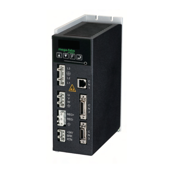
MD20UE01-2109 D1 Servo Drive User Manual Wiring 4.3 Wiring for motor ◼ Wiring for motor mega-fabs D1 series servo drive Shield ground Motor Grounding Figure4.3.1 4.4 Wiring for regenerative resistor Regenerative resistor is optional. ◼ Wiring for regenerative resistor mega-fabs... -
Page 50: Wiring For Control Power And Brake
MD20UE01-2109 Wiring D1 Servo Drive User Manual 4.5 Wiring for control power and brake For wiring 24 V DC control power and brake, please refer to figure 4.5.1. If there is no brake, connect +24 V to the +24 V pin (Pin3) of Wago standard connector 721-103, and connect 0 V to RTN pin (Pin 1). If there is brake, connect brake output pin (BRK) with relay. -
Page 51: Wiring For Control Signals (Cn2)
MD20UE01-2109 D1 Servo Drive User Manual Wiring (2) Connection for RS232 communication Use HIWIN LMACR21D RS232 communication cable. mega-fabs D1 series servo drive RS232 port Figure4.6.1 (3) CN1 RJ11 pin assignment Figure4.6.2 4.7 Wiring for control signals (CN2) (1) Pin assignment Table4.7.1... - Page 52 Ref + Positive pin for analog command input Ref - Negative pin for analog command input D1 model: I12, general-purpose input signal Group D (Programmable) Note: The high-level input voltage of pulse command and PWM command must be greater than 2 V. The low-level input voltage must be lower than 0.8 V.
-
Page 53: Wiring Diagram For Digital Inputs
Wiring diagram for digital inputs The CN2 connector on D1 servo drive provides 9 digital inputs. The input interface circuit is shown in the figure below. The maximum voltages for I9 and I10 are 12 V, and the maximum voltages for other inputs can be 24 V. - Page 54 MD20UE01-2109 Wiring D1 Servo Drive User Manual (1) The wiring example for general-purpose digital inputs (The output type of controller is sink.) The input group should be set as pull up in Lightening. If the photoelectric switch in controller is using NPN transistor...
-
Page 55: Wiring Diagram For Digital Outputs
4.7.2 Wiring diagram for digital outputs The CN2 connector on D1 servo drive provides 3 digital outputs (O1~O3). The output interface circuit is shown in the figure below. The outputs are open-drain outputs with allowable maximum voltage 40 V and maximum current 0.3 A. - Page 56 MD20UE01-2109 Wiring D1 Servo Drive User Manual (1) The wiring example for connecting to controller mega-fabs Controller D1 series servo drive Figure4.7.2.2 (2) The wiring example for connecting to relay When a relay is used, please also connect a diode with the relay, please refer to the figure below.
-
Page 57: Wiring Diagram For Pulse Command Input
MD20UE01-2109 D1 Servo Drive User Manual Wiring (3) Wiring example for directly connecting to external load The output can be directly connected to load (For example, indicator). For the wiring method, please refer to the figure below. The voltage and current of external DC power cannot exceed 40 V and 0.3... - Page 58 D1 Servo Drive User Manual (2) Wiring example for controller sending single-ended signal When D1 servo drive is used with controller sending single-ended signal, pulse adapter cable (815AB3) must be connected to CN2. Refer to the figure below. The pin assignment of the pulse adapter cable (815AB3) is the same as CN2, except for pin 23 and pin 22.
- Page 59 (3) In Lightening, go to Mode tab in Configuration center and select Single ended signals. Refer to table 4.7.3.2 while connecting HIWIN pulse control cable (LMACK30R) with pulse adapter cable (815AB3). When other cable is used, please refer to the signals on the female end of the pulse adapter cable (815AB3).
- Page 60 MD20UE01-2109 Wiring D1 Servo Drive User Manual (3) Wiring example for controller sending single-ended signal and pulse adapter cable (815AB3) is not used External resistor is required to ensure the NPN transistor output of controller can meet the lowest limit of breakover current, so operating velocity can be reached and pulse reception can be normal.
- Page 61 Note: This table is not applicable to CN2 on D1 servo drive. Pin 23 on the female end of pulse adapter cable (815AB3) is for 12~24 V input, but CN2-Pin 23 on D1 servo drive is for 0 V reference.
- Page 62 MD20UE01-2109 Wiring D1 Servo Drive User Manual (2) Use external resistor Voltage R resistance (0.5 W) Pulse adapter cable (815AB3) Figure4.7.3.6 ◼ Wiring example for PLC pulse input (1) In the figure below, Mitsubishi PLC FX3U-48MT/□S is used as the example for the wiring of Pulse/Dir and A/B single-ended (NPN) commands.
-
Page 63: Wiring Diagram For Encoder Feedback Pulse Output
MD20UE01-2109 D1 Servo Drive User Manual Wiring (2) In the figure below, Mitsubishi PLC FX3U-48MT/□S is used as the example for the wiring of CW/CCW single-ended (NPN) command. Power supply Mitsubishi Pulse adapter cable (815AB3) Figure4.7.3.8 4.7.4 Wiring diagram for encoder feedback pulse output... -
Page 64: Wiring Diagram For Analog Command
MD20UE01-2109 Wiring D1 Servo Drive User Manual (2) Wiring example (Controller is using optical coupling.) mega-fabs Controller D1 series servo drive Figure4.7.4.2 4.7.5 Wiring diagram for analog command The input impedance is 10 KΩ and the range of voltage command is ±10 V. -
Page 65: Wiring Diagram For Pwm Command Input
4.7.6 Wiring diagram for PWM command input In velocity mode and force/torque mode, in addition to analog command, D1 servo drive can also receive PWM command. Two PWM command types are supported, PWM 50% and PWM 100%. For more information, please refer to section 5.2.4. -
Page 66: Wiring For Feedback Signals (Cn3)
MD20UE01-2109 Wiring D1 Servo Drive User Manual 4.8 Wiring for feedback signals (CN3) (1) D1--2 CN3 pin assignment Table4.8.1 Signal Function Frame ground For connecting cable shield Signal ground and +5 Vdc ground If double-shielded cable is used, it is for connecting the inner shield. - Page 67 MD20UE01-2109 D1 Servo Drive User Manual Wiring (2) D1--3 CN3 pin assignment Table4.8.2 Signal Function Frame ground For connecting cable shield Signal ground and +5 Vdc ground If double-shielded cable is used, it is for connecting the inner shield. Encoder and Hall sensor +5 Vdc power output The total load current cannot exceed 400 mA.
-
Page 68: Wiring Diagram For Digital Incremental Encoder
MD20UE01-2109 Wiring D1 Servo Drive User Manual 4.8.1 Wiring diagram for digital incremental encoder When Renishaw digital optical scale (Encoder alarm signal is supported.) is used, the wiring diagram is as below. When digital incremental encoder (Encoder alarm signal is not supported.), remove the wire connected to pin 18 on CN3. -
Page 69: Wiring Diagram For Motor Over Temperature Protection
D1 Servo Drive User Manual Wiring 4.8.3 Wiring diagram for motor over temperature protection When HIWIN motor is used, I5 input group B must be pull-up, so the motor over temperature protection can be normal. mega-fabs D1 series servo drive... -
Page 70: Ethercat Communication (Cn4)
MD20UE01-2109 Wiring D1 Servo Drive User Manual 4.9 EtherCAT communication (CN4) (1) Pin assignment Table4.9.1 Signal Function Data transmission (Positive) Data transmission (Negative) Data reception (Positive) EtherCAT Gnd EtherCAT signal ground EtherCAT Gnd EtherCAT signal ground Data reception (Negative) EtherCAT Gnd... -
Page 71: Accessories Of D1 Servo Drive
MD20UE01-2109 D1 Servo Drive User Manual Wiring 4.10 Accessories of D1 servo drive (1) Motor power cable Table4.10.1 Product Name Model Description Applicable linear motor: LMS, LMSA, LMC-EFE and LMC-EFF series LMACSD Supports motor over temperature signal. (Withstand voltage 500 Applicable linear motor: LMCA, LMCB, LMCC, LMCD, LMCE, LMACSK... - Page 72 MD20UE01-2109 Wiring D1 Servo Drive User Manual LMACSL Table4.10.4 Cable Length LMACSF Table4.10.5 Cable Length LMACST Table4.10.6 Cable Length LMACSJ Table4.10.7 Cable Length LMACSQ Table4.10.8 Cable Length LMACSP Table4.10.9 Cable Length 4-30 HIWIN MIKROSYSTEM CORP.
- Page 73 Table4.10.11 Cable Length LMACEJ Table4.10.12 Cable Length D1--2: TMS, TMNE, TMNEH and TMNR torque motors Table4.10.13 Product Name Model Description For JENA analog encoder Applicable torque motor: TMS, TMNE, TMNEH and TMNR series LMACEAA Supports motor over temperature signal.
- Page 74 10 11 12 13 14 15 16 Length D1--3: linear motor Table4.10.16 Product Name Model Description For Renishaw digital optical scale and HIWIN magnetic scale, D type 15 pin LMACEAW Supports digital encoder alarm signal. Feedback Do not support Hall signal. Signal Cable For Renishaw digital optical scale and HIWIN magnetic LMACEAV...
- Page 75 MD20UE01-2109 D1 Servo Drive User Manual Wiring D1--4: TMY and TMNA torque motors Table4.10.19 Product Name Model Description Dual resolver Applicable torque motor: TMY and TMNA Feedback LMACEAU series Signal Cable Supports over temperature signal. is motor model. stands for cable length (Unit: m), refer to the table below: LMACEAU...
- Page 76 MD20UE01-2109 Wiring D1 Servo Drive User Manual 815AB3 Table4.10.24 Cable Length (4) RS232 communication cable Table4.10.25 Product Name Model Description RS232 2 meters Communication LMACR21D RJ11 connector for connecting Cable to servo drive (5) Connector kit and EMC kit Connector kit Table4.10.26...
- Page 77 MD20UE01-2109 D1 Servo Drive User Manual Wiring EMC kit Table4.10.27 Product Name Model Description Qty. Single-phase filter FN2090-10-06 D1 EMC (Rated current: 10 A, Leakage current: 0.67 mA) accessory kit D1-EMC1 (single-phase) EMI Core KCF-130-B Three-phase filter FN3258-7-45 D1 EMC...
- Page 78 MD20UE01-2109 Wiring D1 Servo Drive User Manual (2) D1-EMC2 Figure4.10.2 (3) D1-EMC3 Figure4.10.3 4-36 HIWIN MIKROSYSTEM CORP.
- Page 79 MD20UE01-2109 D1 Servo Drive User Manual Wiring (4) D1-EMC4 Figure4.10.4 Harmonic suppression reactor Table4.10.28 Product Name Model Description 1. The servo drive complies with EN61000-3-2 Single-phase Class A. TS10C-16 AC Reactor 2. Reactance: 2 mH (at 60 Hz 16 A/220 V) 3.
- Page 80 MD20UE01-2109 Wiring D1 Servo Drive User Manual (7) Heat sink Table4.10.30 Product Name Model Description External Heat D1-H1 Standard Sink 4-38 HIWIN MIKROSYSTEM CORP.
-
Page 81: Servo Drive Configuration
Configuration center ........................... 5-8 5.2.1 Setting parameters of motor ....................... 5-9 5.2.2 Setting parameters of encoder ......................5-12 5.2.2.1 HIWIN standard encoder ....................... 5-14 5.2.2.2 User-defined encoder setting ......................5-15 5.2.2.3 Setting encoder output ........................5-16 5.2.3 Setting Hall sensor ..........................5-19 5.2.4... -
Page 82: Installation And Communication
D1 Servo Drive User Manual 5.1 Installation and communication Lightening is the human machine interface of D1 servo drive. Connect PC and D1 servo drive via RS232 connection for servo drive initialization, setting, operation, test run and parameter saving in Lightening. -
Page 83: Communication Setup
Section 5.1.2 will introduce how to set up RS232 communication and mega-ulink communication. For CoE communication, please refer to HIWIN CoE Drive User Guide. While using mega-ulink communication or CoE communication, it is suggested to use network card with the network chip certified by Beckhoff. - Page 84 MD20UE01-2109 Servo Drive Configuration D1 Servo Drive User Manual The communication setting window is shown as figure 5.1.2.2. In lightening Communication Setup window, BPS field shows transmission rate. The default setting of transmission rate is 115,200 and should not be changed. Port field shows communication port. All the communication ports of PC will be listed.
- Page 85 MD20UE01-2109 D1 Servo Drive User Manual Servo Drive Configuration (2) mega-ulink communication While using mega-ulink communication for the first time, please download and install WinPcap. After the installation of WinPcap completes, click on Tools and select Communication setup… to open lightening Communication Setup window.
-
Page 86: Main Window
MD20UE01-2109 Servo Drive Configuration D1 Servo Drive User Manual One slave is connected. Figure5.1.2.5 Figure5.1.2.6 5.1.3 Main window After connection is established, the main window of Lightening is shown as figure 5.1.3.1. Right click on the axis and select Rename to change axis name, or directly click on the axis to change axis name. - Page 87 MD20UE01-2109 D1 Servo Drive User Manual Servo Drive Configuration (1) Toolbar : Open the operation window for PDL program. : Save the parameters in the servo drive RAM as file. : Load parameters from file to the servo drive RAM.
-
Page 88: Configuration Center
Refer to sections 5.2.1~5.2.5 for the detailed instructions of the above settings. Note: If HIWIN torque motor is used, encoder parameters of the torque motor will be automatically set after the model is selected. If HIWIN linear motor is used, linear digital 1 um encoder will be automatically selected. -
Page 89: Setting Parameters Of Motor
Servo Drive Configuration 5.2.1 Setting parameters of motor D1 servo drive supports linear motor and torque motor. The first page in Configuration center is for setting . In motor parameters. The supported motors are listed by groups and can be found under each groups, user is able to select HIWIN motors, such as LMC, LMS, TMS, etc. - Page 90 D1 Servo Drive User Manual Figure5.2.1.2 (2) Torque motor Motor parameters Select the model of HIWIN torque motor to display and set motor parameters. Operation parameters Total moment of inertia: Moment of inertia of torque motor (rotor included) (Unit: kg*(m^2)) Operation...
- Page 91 Servo Drive Configuration (3) Customized motor Input motor parameters of motors other than HIWIN standard models. For linear motor, click on Linear in figure 5.2.1.4 and click on Customized Linear. Input necessary parameters according to the motor specification. After parameters are set, the parameter settings can be saved as file (*.mot) and be loaded anytime.
-
Page 92: Setting Parameters Of Encoder
(*.enc) and be loaded anytime. D1 servo drive is able to detect encoder signal error. The default delay time is set to 200 ms. If some encoders require longer power on time, set suitable delay time in Power-on time field to avoid “Encoder error”. - Page 93 D1 Servo Drive User Manual Servo Drive Configuration D1 servo drive can be used with digital encoder and analog encoder, such as optical scale, magnetic scale, rotary encoder, etc. The supported encoders can be categorized into the following four types:...
-
Page 94: Hiwin Standard Encoder
Rotary and Analog 3600 periods 0.3 arc sec. The specifications of rotary analog encoders used by HIWIN TMS series are shown in table 5.2.2.1.1. If other multiplier factor or resolution is required, user is allowed to input encoder information by himself or select other selection. For user-defined encoder setting, please refer to section 5.2.2.2. -
Page 95: User-Defined Encoder Setting
(Unit: um/count) will be automatically calculated and displayed. Figure5.2.2.2.2 (3) Rotary-digital encoder Set the resolution per revolution (Unit: counts/rev). D1 servo drive calculates the linear resolution (Unit: um/counts) of the motor based on the screw pitch and encoder resolution set by user. Figure5.2.2.2.3 HIWIN MIKROSYSTEM CORP. -
Page 96: Setting Encoder Output
5.2.2.3 Setting encoder output D1 servo drive outputs AqB signal via CN2. If needed, connect to controller via CN2. In the encoder output setting area (figure 5.2.2.3.1), user is able to select Use buffered encoder or Use emulated encoder. The value in Output Resolution field will be updated. - Page 97 MD20UE01-2109 D1 Servo Drive User Manual Servo Drive Configuration Figure5.2.2.3.2 (2) Emulated encoder output When emulated encoder output is selected, the signals received from encoder will be scaled before the signals are output to controller. In some cases, such as when controller cannot receive encoder signals sent at high frequency, the scaling can be set to 10:1 to let ten encoder counts equal one emulated encoder output.
- Page 98 D1 Servo Drive User Manual (3) Emulated Z-phase signal output This function is supported in: MD-36-SR, MD-18-SR (For TMX series motor), MD-36-S2-01, D1-36-T01, D1--E and D1--F This function can be used when: When the bandwidth of controller is unable to receive Z-phase signal, this function can enlarge the output range of Z-phase signal to prevent the controller from missing Z-phase signal.
-
Page 99: Setting Hall Sensor
Setting Hall sensor Since D1 servo drive is able to complete phase initialization without Hall sensor, None is selected in the setting page shown in figure 5.2.3.1. Only when Hall sensor is used, the setting of Hall sensor is required. - Page 100 MD20UE01-2109 Servo Drive Configuration D1 Servo Drive User Manual ◼ Hall phase check function This function is only available when digital Hall sensor is used. If Enable hall phase check is selected, after phase initialization completes, the program will inspect if the commutation is correct or if there is abnormal disconnection.
-
Page 101: Setting Operation Mode
For controller which only sends pulse command, select position mode to receive pulse command from the controller. The closed-loop control is handled by the servo drive. D1 servo drive supports three pulse types and two signal types. Electronic gear ratio is provided for application which requires fast movement. - Page 102 MD20UE01-2109 Servo Drive Configuration D1 Servo Drive User Manual Figure5.2.4.2 (2) Velocity mode For controller which sends analog command or PWM command, select velocity mode. The ratio (scaling) between external command and velocity can be set in the setting page in figure 5.2.4.3. Set 1 V equals what velocity in mm/s (linear motor) or rpm (torque motor).
- Page 103 MD20UE01-2109 D1 Servo Drive User Manual Servo Drive Configuration (3) Force/torque mode Another operation mode which can be used with controller sending analog command or PWM command is force/torque mode. The ratio (scaling) between external command and current can be set in the setting page in figure 5.2.4.4.
-
Page 104: Saving Configuration
MD20UE01-2109 Servo Drive Configuration D1 Servo Drive User Manual 5.2.5 Saving configuration After the settings described in sections 5.2.1 to 5.2.4 are completed, click on OK button. Then the page in figure 5.2.5.1 will appear and display the parameters of previous setting and current setting. Ensure the parameters are correct and click on Send to RAM button to save these parameters to the servo drive RAM. -
Page 105: Auto Phase Center
MD20UE01-2109 D1 Servo Drive User Manual Servo Drive Configuration 5.3 Auto phase center Click on on the toolbar or select Auto phase center from the submenu of Conf./Tune to open Auto phase center. Note: While performing phase initialization, the motor speed must be lower than 1/6 * (pole pair pitch)/s. - Page 106 MD20UE01-2109 Servo Drive Configuration D1 Servo Drive User Manual (2) Phase initialization mode: SW method 1 For SW method 1, Hall sensor is not required and motor only needs to move for a small distance to complete phase initialization. Two parameters, st_cg and st_vpg, must be adjusted before using SW method 1, please refer to section 11.2.
- Page 107 MD20UE01-2109 D1 Servo Drive User Manual Servo Drive Configuration Figure 5.3.3 Phase initialization mode: SW method 5 (without Hall sensor) (4) Phase initialization mode: STABS STABS is for using absolute resolver to perform phase initialization. Figure 5.3.4 Phase initialization mode: STABS HIWIN MIKROSYSTEM CORP.
-
Page 108: Inspection Before Auto Phase Initialization
MD20UE01-2109 Servo Drive Configuration D1 Servo Drive User Manual 5.3.1 Inspection before auto phase initialization Check the following items before auto phase initialization. (1) Check if motor power cable is correctly connected. (2) Check if encoder signal is normal. (3) Check if the servo drive receives hardware enable signal, please refer to chapter 12. - Page 109 MD20UE01-2109 D1 Servo Drive User Manual Servo Drive Configuration Step Figure Description Testing moving direction in SM mode: Drag the slider bar leftward and rightward to move the motor. The motor moves in positive direction while dragging slider rightward. The motor moves in negative direction while dragging the slider bar leftward.
- Page 110 MD20UE01-2109 Servo Drive Configuration D1 Servo Drive User Manual Step Figure Description Adjusting phase initialization: The motor only needs to move for a small distance to complete phase initialization. After tuning in step 5 completes, check the tuning result by the following steps.
- Page 111 MD20UE01-2109 D1 Servo Drive User Manual Servo Drive Configuration ◼ Phase initialization when SW method 5 is used When motor is used in vertical direction and is with mechanical brake, check the checkbox of Keep brake always active before phase initialization.
-
Page 112: Precautions For Auto Phase Initialization
MD20UE01-2109 Servo Drive Configuration D1 Servo Drive User Manual 5.3.3 Precautions for auto phase initialization (1) The current for enabling Pay attention to the following when setting the value in Current (SM mode) field in Auto phase center. ⚫ The current must be less than the upper limit of the continuous current of motor. If user is not sure about the load, please start with small current first. -
Page 113: I/O Setting
(1) Setting trigger method The digital inputs of D1 servo drive are divided into four groups, A, B, C and D group. Each group can be set as pull up or pull down. The setting must based on the wiring of the servo drive. Select pull up when the wiring is sink type. - Page 114 MD20UE01-2109 Servo Drive Configuration D1 Servo Drive User Manual (2) Selection for input function Click on , the drop-down list shown in figure 5.4.1.2 will appear. Figure5.4.1.2 Table5.4.1.1 Input functions Abbr. Input Function Description Trigger Method Enable or disable axis.
- Page 115 Electronic gear select (DIV1) Note: V means the input function is supported in the operation mode and can be assigned to I1~I12 (except I7 and I8). Table5.4.1.3 Default input functions of D1 servo drive Non-CoE Model CoE Model Pull Up/Pull Down...
- Page 116 MD20UE01-2109 Servo Drive Configuration D1 Servo Drive User Manual (3) Indicator If indicator becomes green, it means the set function is activated. If not, it means the function is not activated. (4) Logic setting If Invert is selected, the trigger condition is inverted.
- Page 117 MD20UE01-2109 D1 Servo Drive User Manual Servo Drive Configuration Applicable Input Function Switch to secondary mode Operation Mode Default Wiring Abbr. None Refer to section 4.7.1. Input Diagram ◆ Function Use I/O signal from controller to switch between operation modes.
- Page 118 MD20UE01-2109 Servo Drive Configuration D1 Servo Drive User Manual Applicable Input Function Electronic gear select (DIV1) Operation Mode Default Wiring Abbr. DIV1 None Refer to section 4.7.1. Input Diagram ◆ Function This input function is used to switch between two electronic gear ratios.
- Page 119 MD20UE01-2109 D1 Servo Drive User Manual Servo Drive Configuration Applicable Input Function Zero speed clamp Operation Mode Default Wiring Abbr. None Refer to section 4.7.1. Input Diagram ◆ Function This input function can only be used in velocity mode and is level triggered. When the input signal is ON and the motor speed is equivalent to or slower than the speed set for activating brake, the operation mode will be changed to stand-alone mode and the motor is stopped at current position.
- Page 120 MD20UE01-2109 Servo Drive Configuration D1 Servo Drive User Manual Applicable Input Function Zero speed clamp Operation Mode Default Wiring Abbr. None Refer to section 4.7.1. Input Diagram Zero speed clamp is activated when I2 is ON. Applicable Input Function Clear error...
-
Page 121: Digital Outputs
5.4.2 Digital outputs D1 servo drive provides four sets of programmable digital outputs. Three outputs (O1 to O3) are general-purpose outputs which locate on connector CN2. One output (O4) which locates on the connector for 24 V power supply is for brake and can also be used as general-purpose output. - Page 122 MD20UE01-2109 Servo Drive Configuration D1 Servo Drive User Manual (3) Logical value The logical value of each output is displayed. The displayed value can be TRUE or FALSE. (4) Invert output voltage If needed, select Invert voltage to invert the polarity of output voltage. Please be noted the internal logical value of the servo drive will not be affected.
- Page 123 Homing failed. Pulse command and In position mode, both pulse command and homing command PCHC homing conflict are received at the same time. Table5.4.2.2 Default output settings of D1 servo drive Non-CoE Model CoE Model Invert Trigger Condition Trigger Condition...
- Page 124 MD20UE01-2109 Servo Drive Configuration D1 Servo Drive User Manual Applicable Output Function Zero Speed Detected Operation Mode Default Wiring Abbr. ZSPD Refer to section 4.7.2. Output Diagram ◆ Function This signal is output when motor speed is close to zero.
- Page 125 MD20UE01-2109 D1 Servo Drive User Manual Servo Drive Configuration Applicable Output Function Errors Operation Mode Default Wiring Abbr. Refer to section 4.7.2. Output Diagram ◆ Function User is allowed to output error statuses. ◆ Description User can select Errors (Default output: O2) for one output in Outputs tab in I/O center.
-
Page 126: Setting In-Position Signal
After that, motor goes into target radius. D1 servo drive supports in-position settings for user to set target radius and debounce time to observe if motor has reached target position. In-position settings are only available in position mode and stand-alone mode. - Page 127 MD20UE01-2109 D1 Servo Drive User Manual Servo Drive Configuration Table5.5.1 Parameter Description Motor will be regarded as in-position after position error is within Target radius target radius. The default value is 100 times of encoder resolution. Position error needs to be within target radius for the set debounce Debounce time time for motor to be regarded as in-position.
- Page 128 MD20UE01-2109 Servo Drive Configuration D1 Servo Drive User Manual Figure 5.5.2 In-position signal when debounce time is set to 0 ms. (2) From figure 5.5.2, the longest time duration is 1.5 ms. Set debounce time to a value which is slightly larger than 1.5 ms.
-
Page 129: Homing
MD20UE01-2109 D1 Servo Drive User Manual Servo Drive Configuration 5.6 Homing Click on to go to Application center. The setting page for homing is in Homing tab, as figure 5.6.1. For standard digital encoder and analog encoder, refer to figure 5.6.1. For absolute resolver, refer to figure 5.6.2. - Page 130 The maximum search time of homing procedure Home offset Home offset D1 servo drive provides four homing methods: (1) Homing by using left side and right side conditions, refer to section 5.6.1. (2) Homing by using near home sensor or index signal, refer to section 5.6.2.
- Page 131 MD20UE01-2109 D1 Servo Drive User Manual Servo Drive Configuration After homing method is set, click on Home button in Performance center. During homing, Homed indicator will keep flashing. If homing succeeds, Homed indicator becomes green ( ). If the time set for time out elapses, it means homing fails.
-
Page 132: Homing By Left Side And Right Side Conditions
Homing by left side and right side conditions Homing by left side and right side conditions is a built-in homing method of D1 servo drive. Home position is the middle point of left side and right side conditions. The left side and right side conditions can be limit switches or end stops. - Page 133 MD20UE01-2109 D1 Servo Drive User Manual Servo Drive Configuration Table5.6.1.1 Parameter No. Parameter Selection Description Left Move to the left first. ① Initial moving direction Right Move to the right first. None Do not use left side condition. ② Left side condition End stop Move to the left to find end stop.
- Page 134 MD20UE01-2109 Servo Drive Configuration D1 Servo Drive User Manual Exception: (1) Left side condition is set to None and Right side condition is set to End Stop or Right Limit Switch. The initial moving direction (parameter ①) is set to left, as figure 5.6.1.3. The homing fails and Homed indicator becomes red.
-
Page 135: Homing By Near Home Sensor Or Index Signal
Homing by near home sensor or index signal D1 servo drive supports homing by near home sensor or index signal. Set input function Near Home Sensor in I/O center. This input function is triggered by external switch. After near home sensor is found, set to search for index signal in the left side or right side and use it as home position to have better accuracy. - Page 136 MD20UE01-2109 Servo Drive Configuration D1 Servo Drive User Manual If user would like to perform homing by using near home sensor, connect photoelectric switch or mechanical switch to the digital input of the servo drive. Take I2 as an example in figure 5.6.2.2. Go to I/O center to set the input function of I2 as Near Home Sensor.
-
Page 137: Homing By Single-Turn Absolute Encoder
MD20UE01-2109 D1 Servo Drive User Manual Servo Drive Configuration 5.6.3 Homing by single-turn absolute encoder With single-turn absolute encoder, the servo drive is able to know the position of the motor within one revolution and how far the motor must move to reach the home position by calculation. User must decide to let motor move towards left side or right side, or along the shortest path for homing. -
Page 138: Homing By Cia 402 Standard Homing Method
MD20UE01-2109 Servo Drive Configuration D1 Servo Drive User Manual 5.6.4 Homing by CiA 402 standard homing method Homing by CiA 402 standard homing method is supported in CoE model with Lightening version 0.185 (or later version). The setting window is as figure 5.6.4.1. In figure 5.6.4.1, green line means faster speed is used and orange line means slower speed is used. - Page 139 MD20UE01-2109 D1 Servo Drive User Manual Servo Drive Configuration Homing Description Figure Method Homing with the rising edge of near home sensor signal and left index pulse, starting in positive direction. Outside near home sensor: Search for the rising edge of near home sensor signal at faster speed in positive direction.
- Page 140 MD20UE01-2109 Servo Drive Configuration D1 Servo Drive User Manual Homing Description Figure Method Homing with the rising edge of near home sensor signal and right index pulse, starting in negative direction. Outside near home sensor: Search for the rising edge of near home sensor signal at faster speed in negative direction.
- Page 141 MD20UE01-2109 D1 Servo Drive User Manual Servo Drive Configuration Homing Description Figure Method Homing with index pulse, starting in negative direction. Search for index pulse at slower speed in negative direction. Homing with index pulse, starting in positive direction. Search for index pulse at slower speed in positive direction.
- Page 142 MD20UE01-2109 Servo Drive Configuration D1 Servo Drive User Manual Homing Description Figure Method Homing with absolute position. This homing method is only available for motor with multiturn absolute encoder. (The ninth code of motor model is 4.) Set current position as absolute target position.
- Page 143 MD20UE01-2109 D1 Servo Drive User Manual Servo Drive Configuration ◼ Searching for hard stop When searching for hard stop, two parameters will be used: End stop current and Time. End stop current is the strength of the force while searching for hard stop. Time is the duration of the force. If Time is set to be too small, the servo drive may not correctly identify the hard stop.
-
Page 144: Save Parameters To Flash And Set To Factory Default
MD20UE01-2109 Servo Drive Configuration D1 Servo Drive User Manual 5.7 Save parameters to Flash and set to factory default 5.7.1 Save parameters to Flash Click on (Save parameters from amplifier RAM to Flash) to save current parameters to Flash. The parameters will still be accessible after the servo drive is turned off. - Page 145 MD20UE01-2109 D1 Servo Drive User Manual Servo Drive Configuration Figure5.7.2.2 No button Yes button Figure5.7.2.3 If user is using Lightening version 0.186 or later version, click on Tools and select Set amplifier to factory default from the submenu. Set amplifier to factory default window appears as figure 5.7.2.4.
-
Page 146: Setting Operation Mode Via Lightening
MD20UE01-2109 Servo Drive Configuration D1 Servo Drive User Manual 5.8 Setting operation mode via Lightening 5.8.1 Position mode In position mode, when pulse command is received from controller, the servo drive will move the motor for a corresponding distance. For further information of position mode, please refer to section 3.1.1. The setting of position mode should include mode selection, pulse type selection, electronic gear ratio setting and smooth factor setting. - Page 147 MD20UE01-2109 D1 Servo Drive User Manual Servo Drive Configuration (2) Pulse type selection D1 servo drive supports three pulse types. For more information, please refer to section 3.1.1. For pulse type selection, please refer to below. Table5.8.1.2 Step Figure Description...
-
Page 148: Velocity Mode
Click on Send to RAM button to save parameters to RAM. (2) Smooth factor setting D1 servo drive allows user to set smooth factor. For more information, please refer to section 3.4. For smooth factor setting, please refer to below. Table5.8.1.4... - Page 149 MD20UE01-2109 D1 Servo Drive User Manual Servo Drive Configuration (1) Mode selection For mode selection, please refer to below. Table5.8.2.1 Step Figure Description After Lightening is opened, click on the icon of Configuration center on the toolbar. Or click on Conf./Tune on the menu bar and select Configuration center.
-
Page 150: Force/Torque Mode
5.8.3 Force/torque mode D1 servo drive is able to transform voltage command and PWM command into current command. For more information, please refer to section 3.1.3. The setting of force/torque mode should include mode selection and format setting of command input. After setting, please save parameters to Flash. - Page 151 MD20UE01-2109 D1 Servo Drive User Manual Servo Drive Configuration (1) Mode selection For mode selection, please refer to below. Table5.8.3.1 Step Figure Description After Lightening is opened, click on the icon of Configuration center on the toolbar. Or click on Conf./Tune on the menu bar and select Configuration center.
-
Page 152: Stand-Alone Mode
MD20UE01-2109 Servo Drive Configuration D1 Servo Drive User Manual Step Figure Description After setting, click on OK button. Click on Send to RAM button to save parameters to RAM. 5.8.4 Stand-alone mode In stand-alone mode, the servo drive will drive motor by using internal path planning. For more information, please refer to section 3.1.4. - Page 153 MD20UE01-2109 D1 Servo Drive User Manual Servo Drive Configuration (1) Mode selection For mode selection, please refer to below. Table5.8.4.1 Step Figure Description After Lightening is opened, click on the icon of Configuration center on the toolbar. Or click on Conf./Tune on the menu bar and select Configuration center.
- Page 154 MD20UE01-2109 Servo Drive Configuration D1 Servo Drive User Manual (This page is intentionally left blank.) 5-74 HIWIN MIKROSYSTEM CORP.
-
Page 155: Tuning
Saving and opening signal compensation table ................6-59 6.11 Compensation function for absolute resolver signal ................6-60 6.11.1 Operational description ........................6-60 6.11.2 Enabling signal compensation function .................... 6-62 6.11.3 Saving and opening signal compensation table ................6-62 HIWIN MIKROSYSTEM CORP. -
Page 156: Status Display And Quick View
MD20UE01-2109 Tuning D1 Servo Drive User Manual 6.1 Status display and Quick view In Lightening, status display and Quick view are two essential tools which allow user to know the status of the servo drive and the physical quantities for motion control. -
Page 157: Quick View
MD20UE01-2109 D1 Servo Drive User Manual Tuning 6.1.2 Quick view In the main window, there is an area called Quick view as figure 6.1.2.1. Quick view can display three user-defined physical quantities. The values of these physical quantities will be updated for user to observe and analyze the system. -
Page 158: Function Keys
MD20UE01-2109 Tuning D1 Servo Drive User Manual 6.1.3 Function keys Function keys F6 and F12 can be used when Lightening is in operation. ⚫ F6: Move the main window of Lightening to the top. ⚫ F12: F12 function key is for emergency stop. Press F12 key to stop motion (Refer to section 3.4.) After the motion stops, the motor will be disabled. - Page 159 MD20UE01-2109 D1 Servo Drive User Manual Tuning Below is the example of performing test run by point-to-point (P2P) motion. Table6.2.1 Step Figure Description Click on to enable the motor. Select Set P1 and P2. (If software limits are used, ○...
- Page 160 MD20UE01-2109 Tuning D1 Servo Drive User Manual ① V max: The maximum value of velocity ripple V min: The minimum value of velocity ripple V avg: The average value of velocity ripple ② Velocity Ripple: Velocity ripple (Refer to section 3.9.) For Relative move, user can set the desired travel distance.
-
Page 161: Scope
⑮ Enable sw limit: Enable software limit. This function can limit the travel distance of motor. 6.3 Scope D1 servo drive provides Scope for user to observe essential physical quantities during tuning. User can also use Scope to find out the cause when motor cannot be operated. Click on in Performance center to open Scope. - Page 162 MD20UE01-2109 Tuning D1 Servo Drive User Manual ○ ○ ○ ○ Figure6.3.1 Scope ① Physical quantity: Select the desired physical quantity to be observed. (Refer to section 3.11.) ② Unit: Select the unit for the selected physical quantity. ③ Channel: Select to display how many channels at the same time.(1 to 8) ④...
-
Page 163: Data Collection
MD20UE01-2109 D1 Servo Drive User Manual Tuning 6.4 Data collection In addition to observing physical quantities in Scope, user can also use Data collection which provides more options for data capture, advanced graph display and processing function to observe physical quantities. - Page 164 MD20UE01-2109 Tuning D1 Servo Drive User Manual -Dt: Sampling time -Samples*dt: The total time of Data collection To increase the total time of Data collection, user can simply increase the value in Samples. ② The internal variable name of the selected physical quantity ③...
-
Page 165: Data Collection Via Pdl Program
MD20UE01-2109 D1 Servo Drive User Manual Tuning 6.4.2 Data collection via PDL program To be more precise on Data collection, user can use Sync function in figure 6.4.1.1 to have more flexible and real-time Data collection than event trigger. User needs to add a program fragment with title label “_RecordSync”... -
Page 166: Plot View
MD20UE01-2109 Tuning D1 Servo Drive User Manual 6.5 Plot view Data collected in Data collection window can be plotted as graph. Plot view window provides measurement and calculation functions for analysis. There are five areas in Plot view window: menu bar, toolbar, physical quantity display area, graph display area and timeline scrollbar, please refer to figure 6.5.1. - Page 167 MD20UE01-2109 D1 Servo Drive User Manual Tuning Figure6.5.1.1 (2) Show or hide physical quantities Uncheck the checkbox of physical quantity to hide the graph of that physical quantity. For instance, in figure 6.5.1.2, the checkboxes of pos_err and ref_acc are unchecked. Icon in Plot view window is described as below.
- Page 168 MD20UE01-2109 Tuning D1 Servo Drive User Manual (3) Zoom in and zoom out functions Plot view window allows user to zoom in and zoom out on X axis and Y axis. If user would like to observe a certain segment of a graph, he can use reference lines to select the desired segment and zoom in.
- Page 169 MD20UE01-2109 D1 Servo Drive User Manual Tuning Figure6.5.1.4 (5) Zoom in or zoom out on Y axis If user would like to zoom in on Y axis, user needs to press Ctrl key and left click or press Ctrl key and right click at the same time to show two reference lines (red line and red dotted line) to select a segment, as figure 6.5.1.5.
- Page 170 MD20UE01-2109 Tuning D1 Servo Drive User Manual Figure6.5.1.6 Values will not be automatically updated to fit the graph. Figure6.5.1.7 (6) dt, 1/dt and dSamp When the segment is selected by reference lines, three values (dt, 1/dt and dSamp) will be shown below the graph as figure 6.5.1.3.
-
Page 171: Save And Open File
MD20UE01-2109 D1 Servo Drive User Manual Tuning (7) Display a graph in different channel To display a physical quantity in a different channel, click and hold on the physical quantity until a dotted line box appears. Then drag the physical quantity to the desired channel. -
Page 172: Calculation Functions
MD20UE01-2109 Tuning D1 Servo Drive User Manual 6.5.3 Calculation functions Plot view window provides some calculation functions, such as integration, differentiation, addition and multiplication, etc. User can directly calculate in Plot view window. Besides, Plot view window also provides the maximum value, the minimum value, ripple calculation and spectrum analysis of physical quantity. - Page 173 MD20UE01-2109 D1 Servo Drive User Manual Tuning Figure6.5.3.2 Figure6.5.3.3 (3) Fast Fourier transform (FFT) Click on to show FFT window as figure 6.5.3.4. Select physical quantity to do fast Fourier transform. Take pos_err as an example here. Click on Run FFT button to generate the graph as figure 6.5.3.5.
-
Page 174: Advanced Gain Tuning
The performance can be improved by gain and parameter tunings. For D1 servo drive, the simplest way to enhance the performance of motor is to adjust common gain (Primary CG). The greater the common gain is, the stronger the servo stiffness is. However, if servo stiffness is too strong, system vibration or electrical noise may occur. -
Page 175: Filter
D1 Servo Drive User Manual Tuning If the desired performance cannot be achieved by simply adjusting common gain, D1 servo drive also provides advanced gains for advanced tuning, including filter, acceleration feedforward (Acc feedforward), schedule gains and velocity loop gain (Schedule Gains + vpg), analog input correction and current loop. - Page 176 MD20UE01-2109 Tuning D1 Servo Drive User Manual Figure6.6.1.2 Low-pass filter (2) Notch filter When resonance frequency (For instance, resonance frequency between 10 to 250 Hz) occurs and cannot be fixed by modification of mechanism or improvement of design, user can consider using notch filter.
-
Page 177: Acceleration Feedforward
MD20UE01-2109 D1 Servo Drive User Manual Tuning (3) Automatic resonance suppression filter Automatic resonance suppression filter (f3) will be automatically set and activated as auto gain tuning completes. If resonance cannot be suppressed by automatic resonance suppression filter (f3) after auto gain tuning, go to Advanced gains window and uncheck the checkbox of Activate f3, as figure 6.6.1.1. - Page 178 MD20UE01-2109 Tuning D1 Servo Drive User Manual Step 4: Record the maximum command current during acceleration. In figure 6.6.2.2, the maximum command current is 16. When the motor starts to move, Scope will be as figure 6.6.2.2. Use the icon indicated in figure 6.6.2.2 to show one physical quantity only. Repeatedly click on the icon to display the graph of command current, reference acceleration or position error.
-
Page 179: Schedule Gains And Velocity Loop Gain
MD20UE01-2109 D1 Servo Drive User Manual Tuning Position error is 65 counts. Figure6.6.2.4 After adding acceleration feedforward gain 6.6.3 Schedule gains and velocity loop gain (1) Schedule gains A complete motion can be divided into three phases. (Refer to section 3.7) ①... - Page 180 Figure6.6.3.1 (2) Velocity loop gain (vpg) Velocity loop gain (vpg) is an internal control parameter of D1 servo drive. The initial value of velocity loop gain is automatically calculated from the parameters set in Configuration center. Normally user does not need to modify the value. If needed, user can use Freq analyzer to adjust the value again, please refer to below.
- Page 181 MD20UE01-2109 D1 Servo Drive User Manual Tuning Step 3: Click on to start frequency analysis. Motor will firstly vibrate at low frequency and then generate a high-frequency sound. A frequency response graph will appear as figure 6.6.3.3 after completion. Figure6.6.3.3 Step 4: Left click on the graph to show a reference line (-20dB).
-
Page 182: Offset Correction For Analog Input
Offset correction for analog input While using voltage mode, the voltage command sent from controller could have DC bias. This could distort command and affect performance. D1 servo drive provides offset correction for analog input. Click to automatically measure offset and proceed offset correction. -
Page 183: Current Loop
MD20UE01-2109 D1 Servo Drive User Manual Tuning 6.6.5 Current loop The gains (Ki and Kp) of current loop are calculated based on motor parameters when motor type is selected in Configuration center, and do not need to be adjusted again. However, if the motor parameters are not correctly set, user can use these gains for adjustment. - Page 184 MD20UE01-2109 Tuning D1 Servo Drive User Manual Step 1: Set the desired acceleration, deceleration and travel distance. Perform point-to-point (P2P) motion. Step 2: Open Scope and observe position error and reference velocity, as figure 6.6.6.2. Step 3: Click on (Plot view) in Scope window for analyzing waveforms.
- Page 185 MD20UE01-2109 D1 Servo Drive User Manual Tuning Step 4: As motion command completes, enlarge the graph of position error. Select the desired segment, as figure 6.6.6.3. Click on to zoom in on the segment. For related operation, please refer to section 6.5.
- Page 186 MD20UE01-2109 Tuning D1 Servo Drive User Manual Figure6.6.6.5 Step 7: Zoom in on the segment of low frequency and record the vibration frequency of the maximum amplitude, as figure 6.6.6.6. Step 8: Input the frequency of low-frequency vibration into Frequency field in VSF tab of Advanced gains window.
- Page 187 MD20UE01-2109 D1 Servo Drive User Manual Tuning Step 9: Check the checkbox of enable VSF to enable vibration suppression filter (VSF), as figure 6.6.6.7. Please be noted that do not check or uncheck the checkbox of enable VSF while the motor is moving.
-
Page 188: Friction Compensation
Friction compensation The efficiency and function of motion could be affected by the mechanical friction from transmission component. D1 servo drive provides friction compensation to reduce the effect of friction. Figure6.6.7.1 For how to apply friction compensation, please refer to the instructions below. -
Page 189: Loop Constructor
MD20UE01-2109 D1 Servo Drive User Manual Tuning Position error is greater as motor starts to move. Position error Constant speed motion Friction compensation is applied. Friction compensation is not applied. Figure6.6.7.2 Friction compensation 6.7 Loop constructor In Loop constructor, user is able to check the stability of control system. Loop constructor supports spectrum analysis tools, such as Nyquist plot, Nichols plot and Bode plot and allows user to adjust filters and gains (vpg, vig, ppg and CG). -
Page 190: Load/Save File
MD20UE01-2109 Tuning D1 Servo Drive User Manual Control loops Gain tuning Gain margins and phase margins Filters Spectrum analysis Display adjustment Gain tuning Figure6.7.2 Loop constructor interface 6.7.1 Load/save file While using Loop constructor to analyze control system, the control system and gains must be loaded first. -
Page 191: Tool
MD20UE01-2109 D1 Servo Drive User Manual Tuning After analyzing control system in Loop constructor, user can save the control system and gains. Click on File on the menu bar and select Save from the submenu. The three saving methods are described as below. -
Page 192: Frequency Response Function
MD20UE01-2109 Tuning D1 Servo Drive User Manual 6.7.2.1 Frequency response function Frequency response can be expressed by the transfer functions of dynamic system which show the relationship between input signals and output signals. The control architecture of the servo drive is shown in figure 6.7.2.1.1. -
Page 193: Nyquist
MD20UE01-2109 D1 Servo Drive User Manual Tuning 6.7.2.2 Nyquist Select Nyquist in Loop constructor window to simulate and analyze the frequency responses of velocity open loop (Vel open loop) and position open loop (Pos open loop) of control system. Check the checkbox of Vel open loop or Pos open loop to simulate and analyze its Nyquist plot. -
Page 194: Bode
MD20UE01-2109 Tuning D1 Servo Drive User Manual 6.7.2.3 Bode Select ph+gain in Loop constructor window to simulate and analyze the frequency responses of velocity controller (Vel controller), velocity open loop (Vel open loop), velocity closed loop (Vel close loop), position controller (Pos controller), position open loop (Pos open loop) and position closed loop (Pos close loop). -
Page 195: Nichols
MD20UE01-2109 D1 Servo Drive User Manual Tuning 6.7.2.4 Nichols Select Nichols in Loop constructor window to simulate and analyze the frequency responses of velocity open loop (Vel open loop) and position open loop (Pos open loop). Check the checkbox of Vel open loop or Pos open loop to simulate and analyze its Nichols plot. -
Page 196: Low-Pass Filter
MD20UE01-2109 Tuning D1 Servo Drive User Manual 6.7.3.1 Low-pass filter Low-pass filter in control loop is used to suppress high-frequency noise or machine vibration. Figure 6.7.3.1.1 shows the Bode plot of low-pass filter. Modify the parameters of filter (fr and xi) to simulate how the filter affects the frequency response of control system. -
Page 197: Notch Filter
MD20UE01-2109 D1 Servo Drive User Manual Tuning 6.7.3.2 Notch filter When resonance frequency occurs and cannot be fixed by modification of mechanism or improvement of design, user can consider using notch filter. Figure 6.7.3.2.1 shows the Bode plot of notch filter. Modify the parameters of filter (fr and xi) to simulate how the filter affects the frequency response of control system. -
Page 198: Gain Tuning
MD20UE01-2109 Tuning D1 Servo Drive User Manual 6.7.4 Gain tuning Loop constructor allows user to adjust velocity loop gains (vpg and vig), position loop gain (ppg) and common gain (CG) to simulate the stability of control system after gain tuning. -
Page 199: Spectrum Analysis
MD20UE01-2109 D1 Servo Drive User Manual Tuning 6.7.5 Spectrum analysis The gain margins, phase margins and bandwidth of velocity loop and position loop are provided in Loop constructor window for user to adjust gains to simulate the stability of control system after gain tuning. In Loop constructor window, P margin means phase margin and G margin means gain margin. - Page 200 MD20UE01-2109 Tuning D1 Servo Drive User Manual Figure6.8.1 Digital encoder Figure6.8.2 Analog encoder (2) Checking encoder value Digital encoder signal and analog encoder signal are digital pulse and sine wave signal with 90 degrees phase differences. Manually move motor for a known distance and check if the value in Position field is the same.
-
Page 201: Error Map Function
Normally the positioning accuracy of positioning platform can be measured and corrected by using laser interferometer. With laser interferometer, the errors can be obtained. D1 servo drive provides a function called Error map function, which allows user to input the errors. With the information, the servo drive is able to calculate compensation value between fixed distances by linear interpolation to improve positioning accuracy. -
Page 202: Setting Error Map Function
MD20UE01-2109 Tuning D1 Servo Drive User Manual 6.9.1 Setting error map function To use Error map function, please refer to the instructions below. Step 1: Open Application center and select Error Map tab. Load from Flash/Save to Flash Open/Save file... - Page 203 MD20UE01-2109 D1 Servo Drive User Manual Tuning Reminding user that the modified compensation value has not been saved to the servo drive Flash. Figure6.9.1.2 Setting Error map function Note: After inputting errors into the fields of Error, the input values will be rounded to integer multiples of encoder resolution.
-
Page 204: Enabling Error Map Function
Enabling error map function After Error map table is set in the servo drive, the servo drive is able to compensate the errors after homing. D1 servo drive provides two ways of homing, please refer to below. (1) Homing with controller Set input function Home OK, start err. -
Page 205: Saving And Opening Error Map Table
MD20UE01-2109 D1 Servo Drive User Manual Tuning (2) Homing in stand-alone mode Open Performance center, click on . (Refer to section 6.2.) ◼ How to check if Error map function is enabled If user would like to check if Error map function is enabled or not, go to Error map tab and check Error map active indicator. -
Page 206: Changing The Start Position Of Error Map Function
MD20UE01-2109 Tuning D1 Servo Drive User Manual 6.9.4 Changing the start position of error map function To change the start point of Error map function, click on View on the menu bar and select Advanced from the submenu. The setting page shown in figure 6.9.4.1 will appear. Input the desired start position into the field of Start position. - Page 207 MD20UE01-2109 D1 Servo Drive User Manual Tuning (1) When home offset = 0 and start position = 0 When home offset and start position are both zero, the effective range of Error map function is defined by index. Error map function is applied for operation in forward direction, starting from index.
- Page 208 MD20UE01-2109 Tuning D1 Servo Drive User Manual (3) When home offset = 0 and start position ≠ 0 When home offset is zero and start position is not zero, index will be regarded as reference for the effective range of Error map function. The effective range of Error map function varies with start position.
- Page 209 MD20UE01-2109 D1 Servo Drive User Manual Tuning Home Start Effective Range Offset Position Home offset = 100 Effective range Start position = 50 + Position index Servo drive coordinates = 0 Servo drive coordinates = -100 Home offset Start position...
- Page 210 MD20UE01-2109 Tuning D1 Servo Drive User Manual Home Start Effective Range Offset Position Home offset Start position = -100 = 50 Effective range -100 Servo drive coordinates index + Position Servo drive coordinates = 100 Start position = -100 Home offset...
-
Page 211: Compensation Function For Resolver Signal
MD20UE01-2109 D1 Servo Drive User Manual Tuning Home Start Effective Range Offset Position Home offset = Start position = -100 Effective range -100 -100 + Position index Servo drive Servo drive coordinates = 100 coordinates = 6.10 Compensation function for resolver signal The absolute accuracy of a resolver could be influenced by the quality of its signal. -
Page 212: Operational Description
MD20UE01-2109 Tuning D1 Servo Drive User Manual 6.10.1 Operational description To enable signal compensation function for resolver signal, please refer to below. Step 1: Open Application center. Select Advanced from the submenu of View on the menu bar. Resolver tab appears as figure 6.10.1.1. -
Page 213: Enabling Signal Compensation Function
MD20UE01-2109 D1 Servo Drive User Manual Tuning Figure6.10.1.2 Step 4: Check the checkbox of Step 5: Save the signal compensation table to Flash, please refer to step 4 to step 6 of setting Error map function in section 6.9.1. Step 6: Click on Variable Tuning button in Resolver tab of Application center. -
Page 214: Compensation Function For Absolute Resolver Signal
MD20UE01-2109 Tuning D1 Servo Drive User Manual 6.11 Compensation function for absolute resolver signal The compensation table for absolute resolver signal is set for user and needs to be reset only when the servo drive or motor is changed. Before resetting the compensation table for absolute resolver signal, please initialize the absolute resolver first. - Page 215 MD20UE01-2109 D1 Servo Drive User Manual Tuning Step 6: Click on Check Resolver Data button in figure 6.11.1.2. If the check is OK, Data check window appears as figure 6.11.1.3. If not, Error window appears as figure 6.11.1.4 and please repeat step 5.
-
Page 216: Enabling Signal Compensation Function
MD20UE01-2109 Tuning D1 Servo Drive User Manual Step 7: Go to the main window of Lightening and click on to save parameters to Flash. Step 8: Save the signal compensation table to Flash, please refer to step 4 to step 6 of setting Error map function in section 6.9.1. -
Page 217: Lcd Display
Auto gain tuning ..........................7-27 7.5.5 Setting current position to zero ......................7-28 Setting operation mode via LCD panel ....................7-28 7.6.1 Position mode ........................... 7-28 7.6.2 Velocity mode ............................ 7-34 7.6.3 Force/torque mode ..........................7-36 7.6.4 Stand-alone mode ..........................7-38 HIWIN MIKROSYSTEM CORP. -
Page 218: Lcd Panel
MD20UE01-2109 LCD Display D1 Servo Drive User Manual 7.1 LCD panel 7.1.1 Description 1:X Axis name Page number Display SV RDY Enter key Up key LED indicator Down key F key Figure7.1.1.1 LCD panel Table7.1.1.1 Function description Name Function Display Displays parameter name, value, status and motion. -
Page 219: Description Of Operation Page
MD20UE01-2109 D1 Servo Drive User Manual LCD Display 7.1.2 Description of operation page There are four pages in the LCD display: (1) Home page (2) Display parameters page (3) Change parameters page (4) Actions page Press F key to switch among modes. For the structure of the LCD display, please refer to figure 7.1.2.1. - Page 220 MD20UE01-2109 LCD Display D1 Servo Drive User Manual Feedback 01FBPO Position Reference 02RFPO Position 04POSE Position Error 10FBVE Feedback Velocity 11RFVE Reference Velocity Velocity 12VELE Error Actual 30ACTC Current 31CMDC Command Current 40ANAC Analog -0.0202 Command 41DCBU 0.991 Voltage Amplifier 50AMPT 30.4...
-
Page 221: Home Page
7.2.1. For the description of error message or warning message, please refer to tables 7.2.2 and 7.2.3. For D1 firmware version 0.234, D1 CoE firmware version 0.314 and previous version, the LCD display shows the abbreviation of error message or warning message. For D1 firmware version 0.235, D1 CoE firmware version 0.315 and later version, the LCD display shows error code or warning code. - Page 222 For D1 firmware version 0.234, D1 CoE firmware version 0.314 and previous version, the LCD display shows the abbreviation of error message or warning message. For D1 firmware version 0.235, D1 CoE firmware version 0.315 and later version, the LCD display shows error code or warning code.
-
Page 223: Display Parameters Page
MD20UE01-2109 D1 Servo Drive User Manual LCD Display 7.3 Display parameters page Press Up key or Down key in display parameters page to switch among parameters, please refer to figure 7.3.1. The first line on the LCD display is parameter name. The second line is its value and status. - Page 224 MD20UE01-2109 LCD Display D1 Servo Drive User Manual Displayed Physical Quantity Description Unit Abbreviation 62 I2 Input 2 63 I3 Input 3 64 I4 Input 4 Input 5 (Motor over temperature 65 I5 signal) 66 I6 Input 6 67 I9...
-
Page 225: Change Parameters Page
MD20UE01-2109 D1 Servo Drive User Manual LCD Display 7.4 Change parameters page The third page in the LCD display is change parameters page which is used for setting parameters. There are two areas, commonly-used parameter area and advanced parameter area, please refer to tables 7.4.1 and 7.4.3.1. - Page 226 MD20UE01-2109 LCD Display D1 Servo Drive User Manual Table7.4.1 Table of commonly-used parameters (Set parameters based on actual situation.) LCD No. Function Description Set the maximum output acceleration of motor during Acceleration motion. Set the maximum output deceleration of motor during Deceleration motion.
-
Page 227: Save To Flash
MD20UE01-2109 D1 Servo Drive User Manual LCD Display 7.4.1 Save to Flash For how to save parameters from the servo drive RAM to Flash, please refer to below. Step 1: Press Enter key and select SAVEFL (There is a blinking cursor on the left of the second line.) - Page 228 MD20UE01-2109 LCD Display D1 Servo Drive User Manual Step 1: Press Enter key to go to the editing mode of LCD No. 065 (The dynamic cursor is on the left of the second line.) Step 2: Press Down key once to move the blinking cursor to the position of 0.
- Page 229 MD20UE01-2109 D1 Servo Drive User Manual LCD Display LEVEL ONE LEVEL TWO Press F key to change the function of Up key and Down key to changing parameter. Press Up key twice to let the number become 1. (In the sequence of 0→0→1)
- Page 230 MD20UE01-2109 LCD Display D1 Servo Drive User Manual (Space) Figure7.4.2.2 The switching sequence of numbers 7-14 HIWIN MIKROSYSTEM CORP.
-
Page 231: Advanced Parameter Area
MD20UE01-2109 D1 Servo Drive User Manual LCD Display 7.4.3 Advanced parameter area To go to advanced parameter area, please follow the steps below. Step 1: Press Down key until the LCD display shows “+++”. Press Enter key (There is a blinking cursor on the left of the second line.) to go to advanced parameter area. - Page 232 MD20UE01-2109 LCD Display D1 Servo Drive User Manual Table7.4.3.1 Advanced parameter table (Set parameters based on actual situation.) Name Definition Unit Default Value Max. Min. Set the maximum acceleration of motor during motion (Suggested LM: count/s Refer to section X_acc...
- Page 233 MD20UE01-2109 D1 Servo Drive User Manual LCD Display Name Definition Unit Default Value Max. Min. X_gearRatyio Gear ratio of AC servo motor Vcmd_offs Offset correction of analog input Volt The numerator of electronic gear X_cmd_ext_N ratio (output) The denominator of electronic...
- Page 234 MD20UE01-2109 LCD Display D1 Servo Drive User Manual Name Definition Unit Default Value Max. Min. 2: PWM 100% out_config[0] out_config[1] Setting O4 output signal. out_config[2] out_config[3] out_config[4] 49346 out_config[5] 32828 Setting O1 output signal. out_config[6] out_config[7] out_config[8] out_config[9] Setting O2 output signal.
- Page 235 MD20UE01-2109 D1 Servo Drive User Manual LCD Display Name Definition Unit Default Value Max. Min. 0: Left 1: Right Set whether to search for index when first homing mode is used. X_home_opt0_i 0: Home position is at the middle ndex of travel distance.
- Page 236 MD20UE01-2109 LCD Display D1 Servo Drive User Manual Name Definition Unit Default Value Max. Min. Invert buffered encoder output. LCD.buff_inv 0: Do not invert. 1: Invert. Switch between buffered encoder output and emulated encoder LCD.emu_or_b output 0: Buffered encoder output 1: Emulated encoder output Invert input I1.
- Page 237 MD20UE01-2109 D1 Servo Drive User Manual LCD Display Name Definition Unit Default Value Max. Min. Group C-Switch between high LCD.pullC_dow level and low level (Pull C). n_up 0: High level 1: Low level Group D-Switch between high LCD.pullD_dow level and low level (Pull D).
-
Page 238: Actions Page
MD20UE01-2109 LCD Display D1 Servo Drive User Manual 7.5 Actions page Actions page allows user to perform functions such as enabling, disabling, jog, absolute motion and set current position to zero. Motion velocity and target position can also be set in this page. Press Up key or Down key to select the required function, please refer to figures 7.5.1 and 7.5.2. - Page 239 MD20UE01-2109 D1 Servo Drive User Manual LCD Display Enabling/Disabling 4:ENA/DI SV RDY Motion velocity 4:JOG 4:VEL_LC (JOG/ MOV2PO) (Unit: rpm) Set target Start absolute 4:MOV PO 4:MOV2PO position for motion and MOV2PO move to target (Unit: count) position. Jog current Set the current 4:SETZER...
-
Page 240: Enabling And Disabling
MD20UE01-2109 LCD Display D1 Servo Drive User Manual 7.5.1 Enabling and disabling Before using this function to enable or disable motor, ensure external enable signal is input to the servo drive or whether LCD No. 221 (Invert input I1.) is 1. The default setting of I1 is for the input of axis enable signal. -
Page 241: Jog
MD20UE01-2109 D1 Servo Drive User Manual LCD Display 7.5.2 Follow the steps below to perform jog. The operation flow chart is provided in figure 7.5.2.1. Step 1: Press Enter key to show JOG (A solid blinking cursor is on the left of the second line.). -
Page 242: Absolute Motion
MD20UE01-2109 LCD Display D1 Servo Drive User Manual 7.5.3 Absolute motion Follow the steps below to perform absolute motion. The operation flow chart is provided in figure 7.5.3.1. The absolute position of the example below is 2000. Step 1: Press Up key or Down key to show MOV PO for setting target position. For the setting method, please refer to section 7.4.2. -
Page 243: Auto Gain Tuning
MD20UE01-2109 D1 Servo Drive User Manual LCD Display 7.5.4 Auto gain tuning Follow the steps below to perform auto gain tuning (AUTOTU). The operation flow chart is provided in figure 7.5.4.1. Step 1: Press Enter key to show AUTOTU (A solid blinking cursor is on the left of the second line.). -
Page 244: Setting Current Position To Zero
MD20UE01-2109 LCD Display D1 Servo Drive User Manual 7.5.5 Setting current position to zero Follow the steps below to set current position to zero. The operation flow chart is provided in figure 7.5.5.1. Press Up key or Down key to show SETZER. Press Enter key to set current position to zero. - Page 245 MD20UE01-2109 D1 Servo Drive User Manual LCD Display (1) Mode selection The steps of setting position mode via LCD panel are provided in table 7.6.1.1. Table7.6.1.1 Step LCD Display Description Open the parameter editing page 3 SAVEFL of the LCD display.
- Page 246 LCD Display D1 Servo Drive User Manual (2) Pulse type selection D1 servo drive supports three pulse types. For detailed information, please refer to section 3.1.1. The steps of setting pulse type via LCD panel are provided in table 7.6.1.3. Table7.6.1.3...
- Page 247 LCD Display (3) Single-ended pulse signal/differential pulse signal setting D1 servo drive supports both single-ended pulse signal and differential pulse signal. The steps of setting single-ended pulse signal input or differential pulse signal input are provided in table 7.6.1.5. Table7.6.1.5...
- Page 248 D1 Servo Drive User Manual (4) Electronic gear ratio setting D1 servo drive provides two sets of electronic gear ratios. For detailed information, please refer to section 5.4.1. The steps of setting electronic gear ratio are provided in table 7.6.1.7.
- Page 249 MD20UE01-2109 D1 Servo Drive User Manual LCD Display (5) Smooth factor setting Use smooth factor to create S-curve velocity profile or T-curve velocity profile. The setting range is 0~500. For detailed information, please refer to section 3.4. The steps of setting electronic gear ratio are provided in table 7.6.1.9.
-
Page 250: Velocity Mode
7.6.2 Velocity mode D1 servo drive is able to convert voltage command and PWM command into velocity command. For detailed information, please refer to section 3.1.2. The setting of velocity mode includes mode selection and command input type setting. After setting, save parameters to Flash by referring to section 7.4.1. - Page 251 MD20UE01-2109 D1 Servo Drive User Manual LCD Display Step LCD Display Description Press Up key or Down key to set command input type. Note: In this example, analog voltage command input is set. Press Enter key to complete command input type setting.
-
Page 252: Force/Torque Mode
7.6.3 Force/torque mode D1 servo drive is able to convert voltage command and PWM command into current command. For detailed information, please refer to section 3.1.3. The setting of velocity mode includes mode selection and command input type setting. After setting, save parameters to Flash by referring to section 7.4.1. - Page 253 MD20UE01-2109 D1 Servo Drive User Manual LCD Display Step LCD Display Description Press Up key or Down key to set command input type. Note: this example, analog voltage command input is set. Press Enter complete command input type setting. Press and hold Down key to go to LCD No.
-
Page 254: Stand-Alone Mode
MD20UE01-2109 LCD Display D1 Servo Drive User Manual 7.6.4 Stand-alone mode In stand-alone mode, the servo drive performs path planning to drive motor. For detailed information, please refer to section 3.1.4. The setting of stand-alone mode includes mode selection. After setting, save parameters to Flash by referring to section 7.4.1. - Page 255 Hardware limit protection ........................8-8 8.4.2 Software limit protection ........................8-9 Over temperature protection ........................8-10 8.5.1 Motor over temperature protection ....................8-10 8.5.2 Software over temperature protection....................8-10 8.5.3 Servo drive over temperature protection................... 8-10 Overvoltage protection ..........................8-11 HIWIN MIKROSYSTEM CORP.
-
Page 256: Protection Function
MD20UE01-2109 Protection Function D1 Servo Drive User Manual 8.1 Motion protection Motion protection limits or specifies the maximum speed, maximum acceleration, maximum deceleration and deceleration of emergency stop. When the requested speed or acceleration is too high, motion protection will be activated to constrain motion by values set for motion protection. Motion protection varies in different operation mode, please refer to table 8.1.1. - Page 257 MD20UE01-2109 D1 Servo Drive User Manual Protection Function Note: The maximum default setting of Acc. and Dec. of linear motor is 2 G. is the moment of inertia obtained from inertia estimation. In figure 8.1.1, the maximum speed, maximum acceleration and maximum deceleration of motion can be set in the setting area of Motion protection.
- Page 258 MD20UE01-2109 Protection Function D1 Servo Drive User Manual (3) Applicable timing of deceleration of emergency stop (Dec. kill) In the following occasions, deceleration of emergency stop will be used. In position mode or velocity mode, the motor is disabled and emergency stop is activated.
-
Page 259: Position And Velocity Error Protection
8.2.2 Position error warning and velocity error warning In addition to the position error limit described in section 8.2.1, D1 servo drive also provides warning function. When position error or velocity error exceeds the setting in Warning windows, a warning message will appear in the main window of Lightening to inform user. -
Page 260: Brake Protection
D1 Servo Drive User Manual 8.3 Brake protection D1 servo drive supports brake signal output to enable electromagnetic brake to protect motor and mechanism. This is often used for motor of Z axis. The timing of enabling brake is essential in such application. - Page 261 MD20UE01-2109 D1 Servo Drive User Manual Protection Function Table8.3.1 Parameter Description Delay Time for Brake Engagement Maximum time from the time when disabling command is (delMaxEnToBrk) received to the time when brake engages. Deceleration of Emergency Stop Deceleration of motor brake when emergency stop is (Dec.
-
Page 262: Limit Protection
8.4.1 Hardware limit protection D1 servo drive supports hardware limit protection. Hardware limit usually means the photoelectric switch or micro switch installed on positioning platform to identify travel distance. Hardware limit switch is usually a normally-closed sensor. When hardware limit switch is triggered, the servo drive decelerates the motor by the value set for emergency stop (Dec. -
Page 263: Software Limit Protection
8.4.2 Software limit protection In addition to hardware limit protection, D1 servo drive also supports software limit protection. When motor reaches the position of software limit, the servo drive only accepts motion command for moving the motor towards the opposite direction. -
Page 264: Over Temperature Protection
Select Soft-thermal accumulator in Quick view to check the current estimated temperature. 8.5.3 Servo drive over temperature protection D1 servo drive is able to detect servo drive over temperature. When the temperature of the servo drive C, error message “Amplifier over temperature” appears and the motor is stopped. Select reaches 80 Amplifier temperature in Quick view to check the current temperature of the servo drive. -
Page 265: Overvoltage Protection
When the returned energy exceeds the capacity of the capacitors, regenerative resistor must be installed to protect the servo drive by absorbing the returned energy. For D1 servo drive, the voltage threshold for activating regenerative resistor is 390 Vdc; the voltage threshold for deactivating regenerative resistor is 380 Vdc. - Page 266 MD20UE01-2109 Protection Function D1 Servo Drive User Manual (This page is intentionally left blank.) 8-12 HIWIN MIKROSYSTEM CORP.
-
Page 267: Errors And Warnings
Errors and warnings ............................9-1 Error messages and warning messages ....................9-2 Error and warning log ..........................9-5 Automatic error handling ..........................9-8 Troubleshooting ............................9-9 9.4.1 Status indicator ........................... 9-9 9.4.2 Error description and corrective action ..................... 9-10 HIWIN MIKROSYSTEM CORP. -
Page 268: Error Messages And Warning Messages
9.1 Error messages and warning messages If an error occurs, D1 servo drive will activate protection function and display error message in the area of Last error. If a warning occurs, warning message will be displayed in the area of Last warning. - Page 269 MD20UE01-2109 D1 Servo Drive User Manual Errors And Warnings The error messages of D1 servo drive and their meanings are listed in table 9.1.1. Table9.1.1 Error Description Motor short (over current) detected Motor short circuit is detected. Over voltage detected The DC bus voltage inside the servo drive is too big.
- Page 270 MD20UE01-2109 Errors And Warnings D1 Servo Drive User Manual The warning messages of D1 servo drive and their meanings are listed in table 9.1.2. Table9.1.2 Warning Description Left SW limit The left software limit is triggered. Right SW limit The right software limit is triggered.
-
Page 271: Error And Warning Log
9.2 Error and warning log When D1 servo drive detects error or warning, the error or warning will be displayed in the main window of Lightening and will be saved in Errors and Warnings Log, as figure 9.2.1. To prevent user from missing the errors or warnings reported by the servo drive, the errors or warnings occur after power on (24 Vdc) are saved in Errors and Warnings Log. - Page 272 MD20UE01-2109 Errors And Warnings D1 Servo Drive User Manual The frequencies of occurring errors and warnings are saved in Statistics tab of Errors and Warnings Log window. User can know which error or warning frequently occurs. Figure9.2.2 HIWIN MIKROSYSTEM CORP.
- Page 273 MD20UE01-2109 D1 Servo Drive User Manual Errors And Warnings Besides, user can double click on the error or warning in Statistics tab to show Help tips window which provides the cause and corrective action of the selected error or warning. For instance, in figure 9.2.3, the cause and corrective action of error “E03 Position error too big”...
-
Page 274: Automatic Error Handling
D1 Servo Drive User Manual 9.3 Automatic error handling D1 servo drive is able to report error and warning in Lightening. Normally when an error occurs, user needs to perform troubleshooting and then clear the error in Lightening. For convenience and efficiency, Lightening provides an automatic error handling function. -
Page 275: Troubleshooting
Latch Amplifier over temperature error or Latch Under voltage error to enable automatic error handling function. 9.4 Troubleshooting 9.4.1 Status indicator The status indicator of D1 servo drive is indicated in figure 9.4.1.1. Status indicator Figure9.4.1.1 Table9.4.1.1 Indicator... -
Page 276: Error Description And Corrective Action
MD20UE01-2109 Errors And Warnings D1 Servo Drive User Manual 9.4.2 Error description and corrective action Table9.4.2.1 Description Error Message Corrective Action Speed or acceleration is Check if the speed, acceleration and deceleration set limited while sending for motion protection in Performance center are too pulse command or small. - Page 277 If the LED is red, adjust the gap between the reader and scale and check if the scale is clean. While using HIWIN magnetic scale, ensure the gap between the reader and scale is between 0.1 to 0.2 mm. Check if the signal cable is properly connected and is not short-circuited.
- Page 278 MD20UE01-2109 Errors And Warnings D1 Servo Drive User Manual Description Error Message Corrective Action Check if the motor power cable is too old. The equivalent current that Soft-thermal Check continuous current the servo drive outputs threshold instantaneous current for the motor is within its...
-
Page 279: Servo Drive Thermal Curve
Servo drive thermal curve Servo drive thermal curve ..........................10-1 10.1 Operating temperature and cooling ......................10-2 10.2 Heat sink..............................10-3 HIWIN MIKROSYSTEM CORP. 10-1... -
Page 280: Operating Temperature And Cooling
D1 Servo Drive User Manual 10.1 Operating temperature and cooling Figures 10.1.1 and 10.1.2 provide the information of D1 servo drive operating in its maximum allowable ambient temperature with different operating condition and cooling device. The cooling devices include heat sink D1-H1 and fan. The operating conditions are input voltage 120 Vac and 240 Vac. -
Page 281: Heat Sink
MD20UE01-2109 D1 Servo Drive User Manual Servo Drive Thermal Curve ◼ Fan specifications (1) Air flow:153 (CFM) (2) Static pressure:0.43 (Inch-H2O) 10.2 Heat sink D1-H1 heat sink is shown in figure 10.2.1. Figure10.2.1 HIWIN MIKROSYSTEM CORP. 10-3... - Page 282 MD20UE01-2109 Servo Drive Thermal Curve D1 Servo Drive User Manual (This page is intentionally left blank.) 10-4 HIWIN MIKROSYSTEM CORP.
-
Page 283: Advanced Frequency Analysis
Advanced frequency analysis Advanced frequency analysis ........................11-1 11.1 Advanced frequency analysis ........................11-2 11.2 Frequency analyzer ..........................11-3 11.3 SMCL tools ............................... 11-5 HIWIN MIKROSYSTEM CORP. 11-1... -
Page 284: Advanced Frequency Analysis
MD20UE01-2109 Advanced Frequency Analysis D1 Servo Drive User Manual 11.1 Advanced frequency analysis Frequency analyzer is used for advanced frequency analysis when the values of vpg and st_vpg calculated by the auto tuning function in section 5.3.2 cannot meet the requirement. Frequency analyzer measures the actual frequency response of the system and calculates the values of vpg and st_vpg according to the application. -
Page 285: Frequency Analyzer
MD20UE01-2109 D1 Servo Drive User Manual Advanced Frequency Analysis 11.2 Frequency analyzer When frequency analyzer is opened, its default mode is “Stepper/Dcbl plant”. Click on measure frequency. It is normal to have sound or vibration while measuring frequency. After the measurement completes, the result will be shown in the display area. - Page 286 MD20UE01-2109 Advanced Frequency Analysis D1 Servo Drive User Manual When there are several -20 dB/dec segments in the curve, move the -20 dB/dec cursor to the segment which is closest to the top. Figure11.2.2 11-4 HIWIN MIKROSYSTEM CORP.
-
Page 287: Smcl Tools
MD20UE01-2109 D1 Servo Drive User Manual Advanced Frequency Analysis 11.3 SMCL tools When SW method 1 is selected for phase initialization mode, use SMCL tools to adjust st_cg to minimize the movement while performing phase initialization. Click on SMCL tool… button in figure 11.1.1 to open SMCL tools, as figure 11.3.1. - Page 288 MD20UE01-2109 Advanced Frequency Analysis D1 Servo Drive User Manual (2) st_vpg An initial value is calculated by using the physical parameters set in Motor page in Configuration center, such as load mass, moment of inertia, gear ratio and motor type, etc. If improper initial value of st_vpg is set, you may use frequency analyzer (Freq analyzer junior) to do frequency response test to obtain the appropriate value.
-
Page 289: Enabling Motor
Enabling motor 00000 Enabling motor ............................. 12-1 12.1 Enabling method ............................12-2 12.2 Checking enabling state from Lightening ....................12-3 HIWIN MIKROSYSTEM CORP. 12-1... -
Page 290: Enabling Method
MD20UE01-2109 Enabling Motor D1 Servo Drive User Manual 12.1 Enabling method ◼ Enable motor by controller Normally motor is enabled by the command sent from controller via input port. Input function Axis enable is set in digital input I1 (section 5.4.1), as figure 12.1.1. -
Page 291: Checking Enabling State From Lightening
MD20UE01-2109 D1 Servo Drive User Manual Enabling Motor 12.2 Checking enabling state from Lightening When Hardware Enable Input indicator in Lightening becomes green, it means enabling signal is received from controller, as figure 12.2.1. Figure12.2.1 Normally motor is enabled by axis enable signal from controller. Pay attention to the following: (1) When Lightening is an active window, clicking on Disable (F12) button can disable the motor. - Page 292 MD20UE01-2109 Enabling Motor D1 Servo Drive User Manual (This page is intentionally left blank.) 12-4 HIWIN MIKROSYSTEM CORP.
-
Page 293: Parameter Comparison
Parameter comparison Parameter comparison ..........................13-1 13.1 Comparing the parameters in RAM and Flash ..................13-2 HIWIN MIKROSYSTEM CORP. 13-1... -
Page 294: Comparing The Parameters In Ram And Flash
MD20UE01-2109 Parameter Comparison D1 Servo Drive User Manual 13.1 Comparing the parameters in RAM and Flash When motor parameters are modified but have not been saved to Flash, Compare parameters RAM to FLASH window appears as user is closing Lightening or saving error map parameters to Flash (Refer to section 6.9.1.), as figure 13.1.1. - Page 295 MD20UE01-2109 D1 Servo Drive User Manual Parameter Comparison The buttons in Compare RAM to flash window are described as below: ○ 1 Save: Save parameter to the servo drive Flash. ○ 2 Close: Close the window. ○ 3 Up: Go to the previous parameter which has different settings in RAM and Flash.
- Page 296 MD20UE01-2109 Parameter Comparison D1 Servo Drive User Manual (This page is intentionally left blank.) 13-4 HIWIN MIKROSYSTEM CORP.
-
Page 297: Updating Firmware And Loading Pdl
Updating firmware and loading PDL Updating firmware and loading PDL ......................14-1 14.1 Updating servo drive firmware ......................... 14-2 14.2 Loading PDL program ..........................14-4 HIWIN MIKROSYSTEM CORP. 14-1... -
Page 298: Updating Servo Drive Firmware
MD20UE01-2109 Updating Firmware And Loading PDL D1 Servo Drive User Manual 14.1 Updating servo drive firmware To update the firmware of the servo drive, click on Tools in the main window of Lightening. Select Upgrade/Downgrade firmware from the submenu, as figure 14.1.1. Then window in figure 14.1.2 appears. - Page 299 MD20UE01-2109 D1 Servo Drive User Manual Updating Firmware And Loading PDL In Upgrade/Downgrade firmware window, follow the steps below to update firmware. Step 1: Left click on the firmware version to be updated. The selected firmware version will be shown in white text on a blue background.
-
Page 300: Loading Pdl Program
MD20UE01-2109 Updating Firmware And Loading PDL D1 Servo Drive User Manual Note: If power failure or communication interruption occurs during firmware update, Lightening stays in “Boot mode” and cannot be changed even when power is supplied again or communication cable is reconnected, as figure 14.1.6. If this occurs, please contact local distributor. - Page 301 MD20UE01-2109 D1 Servo Drive User Manual Updating Firmware And Loading PDL Step 2: Click on Edit button to open the interface for editing PDL program. Figure14.2.2 Figure14.2.3 Step 3: After PDL program is loaded or editing program codes is completed, click on (Compile) to show PDL compiler window.
- Page 302 MD20UE01-2109 Updating Firmware And Loading PDL D1 Servo Drive User Manual Step 4: Click on (Send to slave) after compilation finishes. Click on Yes button when the dialog shown in figure 14.2.5 appears. Then a window with progress bar appears and closes as PDL program is loaded, as figure 14.2.6.
-
Page 303: Troubleshooting For Interference
Troubleshooting for interference Troubleshooting for interference ........................15-1 15.1 Common mode filter ..........................15-2 HIWIN MIKROSYSTEM CORP. 15-1... -
Page 304: Common Mode Filter
15.1 Common mode filter User can use common mode filter to decrease common mode interference. The model number of HIWIN common mode filter for D1 series servo drive is MF-40-S. For its specifications, please refer to the table below. Table16.1.1... - Page 305 MD20UE01-2109 D1 Servo Drive User Manual Troubleshooting For Interference The dimensions of MF-40-S are shown in the figure below. Figure16.1.2 The wiring of common mode filter, servo drive and motor is shown in the figure below. Shielded Filter Shielded motor...
- Page 306 MD20UE01-2109 Troubleshooting For Interference D1 Servo Drive User Manual Filter (CN1) to servo drive Table16.1.2 The specifications of CN1 connector (input) Description 5 positions and 7.62 mm pitch Cable Size 24-8 AWG Suggested Cable 12 AWG, 600 V Suggested Tool Flathead screwdriver Table16.1.3 The definition of CN1 connector...
- Page 307 MD20UE01-2109 D1 Servo Drive User Manual Troubleshooting For Interference DANGER There is a risk of electric shock. The circuit of connecting servo drive main power and motor to the CN1 and CN2 of MF-40-S is high-voltage. If the precautions are not observed, it is likely to cause machine damage, injury or death.
Need help?
Do you have a question about the D1 and is the answer not in the manual?
Questions and answers