Table of Contents
Advertisement
Advertisement
Chapters
Table of Contents

Subscribe to Our Youtube Channel
Related Manuals for Horton 4100-PLUS


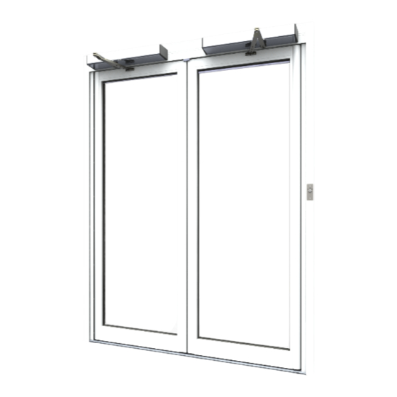
Summary of Contents for Horton 4100-PLUS
- Page 1 ORTON UTOMATICS 4100- P...
- Page 2 ORTON UTOMATICS 4100- P PUSH...
- Page 3 PF18.07 PF18.08 PF18.09 PF18.10 "B" 0 ~ 150mm Standard arm 150 ~ 300mm Extended arm Horton Automatics Ltd DWG NO: 4100 - Plus S Unit A - Hortonwood 31 Telford, Shropshire TF1 7YZ SHEET 1 OF 2 DESCRIPTION: Push Arm Section View...
- Page 4 Spindle + 5mm 25mm 292.5mm 55mm Pivot Horton Automatics Ltd DWG NO: 4100 - Plus S Unit A - Hortonwood 31 Telford, Shropshire TF1 7YZ SHEET 2 OF 2 DESCRIPTION: Push Arm Elevation View DO NOT SCALE DRAWING DIMENSIONS IN MM...
- Page 5 SECTION A-A Horton Automatics Ltd DWG NO: 0101.4100-Plus S Unit A - Hortonwood 31 Telford, Shropshire TF1 7YZ SHEET 1 OF 3 SECTION B-B DESCRIPTION: Frame Mounted Standard Push Arm Sht.1 DO NOT SCALE DRAWING DIMENSIONS IN MM DRAWN Adam Wiggans...
- Page 6 DETAIL C (spindle + 5) PF18.06 – Standard Push Arm Horton Automatics Ltd DWG NO: 0101.4100-Plus S Unit A - Hortonwood 31 Telford, Shropshire TF1 7YZ SHEET 2 OF 3 Sht.2 DESCRIPTION: Frame Mounted Standard Push Arm Sht.2 DO NOT SCALE DRAWING...
- Page 7 Pivot 292.5 362.5 Horton Automatics Ltd DWG NO: 0101.4100-Plus S Unit A - Hortonwood 31 Telford, Shropshire TF1 7YZ SHEET 3 OF 3 Sht.3 DESCRIPTION: Frame Mounted Standard Push Arm Sht.3 DO NOT SCALE DRAWING DIMENSIONS IN MM DRAWN Adam Wiggans...
- Page 8 SECTION A-A Horton Automatics Ltd DWG NO: 0102.4100-Plus S Unit A - Hortonwood 31 Telford, Shropshire TF1 7YZ SHEET 1 OF 3 Sht.1 DESCRIPTION: Lintel Mounted Push Arm Sht.1 SECTION B-B DO NOT SCALE DRAWING DIMENSIONS IN MM DRAWN Adam Wiggans...
- Page 9 DETAIL C (spindle + 5) PF18.09 70mm Spindle 150 max PF 18.08 Push Arm Horton Automatics Ltd DWG NO: 0102.4100-Plus S Unit A - Hortonwood 31 Telford, Shropshire TF1 7YZ SHEET 2 OF 3 Sht.2 DESCRIPTION: Lintel Mounted Push Arm Sht.2...
- Page 10 Pivot 292.5 Horton Automatics Ltd 362.5 DWG NO: 0102.4100-Plus S Unit A - Hortonwood 31 Telford, Shropshire TF1 7YZ SHEET 3 OF 3 Sht.3 DESCRIPTION: Lintel Mounted Push Arm Sht.3 DO NOT SCALE DRAWING DIMENSIONS IN MM DRAWN Adam Wiggans...
- Page 11 SECTION A-A Horton Automatics Ltd DWG NO: 0103.4100-Plus S Unit A - Hortonwood 31 Telford, Shropshire TF1 7YZ SHEET 1 OF 3 Sht.1 DESCRIPTION: Lintel Mounted Extended Push Arm Sht.1 SECTION B-B DO NOT SCALE DRAWING DIMENSIONS IN MM DRAWN...
- Page 12 DETAIL C (spindle + 5) PF18.09 70mm Spindle 300 max PF18.03 Extended Push Arm Horton Automatics Ltd DWG NO: 0103.4100-Plus S Unit A - Hortonwood 31 Telford, Shropshire TF1 7YZ SHEET 2 OF 3 Sht.2 DESCRIPTION: Lintel Mounted Extended Push Arm Sht.2...
- Page 13 Pivot 292.5 362.5 Horton Automatics Ltd DWG NO: 0103.4100-Plus S Unit A - Hortonwood 31 Telford, Shropshire TF1 7YZ SHEET 3 OF 3 Sht.3 DESCRIPTION: Lintel Mounted Extended Push Arm Sht.3 DO NOT SCALE DRAWING DIMENSIONS IN MM DRAWN Adam Wiggans...
- Page 14 SECTION A-A SECTION B-B Horton Automatics Ltd DWG NO: 0104.4100-Plus S Unit A - Hortonwood 31 Telford, Shropshire TF1 7YZ SHEET 1 OF 3 Sht.1 DESCRIPTION: CW Mount Push Sht.1 DO NOT SCALE DRAWING DIMENSIONS IN MM DRAWN Adam Wiggans...
- Page 15 Push Mounting Angle, KAS312 - 38x38x3 (spindle + 5) PF18.09 70mm Spindle PF18.08 Articulated Arm 150max (300 with extended arm) Horton Automatics Ltd DWG NO: 0104.4100-Plus S Unit A - Hortonwood 31 Telford, Shropshire TF1 7YZ SHEET 2 OF 3 Sht.2...
- Page 16 Pivot Push Mounting Angle, KAS312 - 38x38x3 64.5 292.5 362.5 Horton Automatics Ltd DWG NO: 0104.4100-Plus S Unit A - Hortonwood 31 Telford, Shropshire TF1 7YZ SHEET 3 OF 3 Sht.3 DESCRIPTION: CW Mount Push Sht.3 DO NOT SCALE DRAWING...
- Page 17 SECTION A-A Horton Automatics Ltd DWG NO: 0104P.4100-Plus S Unit A - Hortonwood 31 SECTION B-B Telford, Shropshire TF1 7YZ SHEET 1 OF 3 Sht.1 DESCRIPTION: Curtain Wall Mount Push Pair Sht.1 DO NOT SCALE DRAWING DIMENSIONS IN MM DRAWN...
- Page 18 Push Mounting Channel, KAS312 - 38x38x3 (spindle + 5) PF18.09 70mm Spindle PF18.08 Articulated Arm 150max (300 with extended arm) Horton Automatics Ltd DWG NO: 0104P.4100-Plus S Unit A - Hortonwood 31 Telford, Shropshire TF1 7YZ SHEET 2 OF 3 Sht.2...
- Page 19 Pivot Pivot Push Mounting Channel, KAS312 - 38x38x3 292.5 292.5 Horton Automatics Ltd DWG NO: 0104P.4100-Plus S Unit A - Hortonwood 31 Telford, Shropshire TF1 7YZ SHEET 3 OF 3 Sht.3 DESCRIPTION: Curtain Wall Mount Push Pair Sht.3 DO NOT SCALE DRAWING...
- Page 20 SECTION A-A SECTION B-B Horton Automatics Ltd DWG NO: 0104Pa.4100-Plus S Unit A - Hortonwood 31 Telford, Shropshire TF1 7YZ SHEET 1 OF 3 Sht.1 DESCRIPTION: 4100 CW Mount Push Pair with beam Sht.1 DO NOT SCALE DRAWING DIMENSIONS IN MM...
- Page 21 DETAIL D KAS364a - 100x25x2 Box (spindle + 5) PF18.09 70mm Spindle PF18.08 Articulated Arm 150max (300 with extended arm) Horton Automatics Ltd DWG NO: 0104Pa.4100-Plus S Unit A - Hortonwood 31 Telford, Shropshire TF1 7YZ SHEET 2 OF 3 Sht.2 DESCRIPTION: 4100 CW Mount Push Pair with beam Sht.2...
- Page 22 Pivot Pivot KAS364a - 100x25x2 Box 292.5 292.5 Horton Automatics Ltd DWG NO: 0104Pa.4100-Plus S Unit A - Hortonwood 31 Telford, Shropshire TF1 7YZ SHEET 3 OF 3 Sht.3 DESCRIPTION: 4100 CW Mount Push Pair with beam Sht.3 DO NOT SCALE DRAWING...
- Page 23 "A" Shaft Dimension [mm] PF18.07 PF18.08 PF18.09 PF18.10 Dimension "A" [mm] 10 30 700 ~ 1200 150 max Installation Articulated Push Arm (PF18.06 Standard) Maximum Reveal...
- Page 24 "A" Shaft Dimension [mm] PF18.07 PF18.08 PF18.09 PF18.10 Dimension "A" [mm] 10 30 Installation Articulated Push Arm (PF18.06 Standard) Minimum Reveal...
- Page 25 "A" 300 max Shaft Dimension [mm] PF18.07 PF18.08 PF18.09 PF18.10 Dimension "A" [mm] 10 30 300 max Installation Extended Articulated Push Arm (PF18.13) Maximum Reveal...
- Page 26 "A" 150 min Shaft Dimension [mm] PF18.07 PF18.08 PF18.09 PF18.10 Dimension "A" [mm] 10 30 150 min Installation Extended Articulated Push Arm (PF18.13) Minimum Reveal...
- Page 27 ORTON UTOMATICS 4100- P PULL...
- Page 28 PF18.09 PF18.10 "B" 100mm Max "C" As required to level slide arm flush with frame above Horton Automatics Ltd DWG NO: 4100 - Plus S Unit A - Hortonwood 31 Telford, Shropshire TF1 7YZ SHEET 1 OF 2 DESCRIPTION: Pull Arm Section View...
- Page 29 Spindle + 5mm 180mm 600mm Pivot Horton Automatics Ltd DWG NO: 4100 - Plus S Unit A - Hortonwood 31 Telford, Shropshire TF1 7YZ SHEET 2 OF 2 DESCRIPTION: Pull Arm Elevation View DO NOT SCALE DRAWING DIMENSIONS IN MM...
- Page 30 SECTION A-A Horton Automatics Ltd DWG NO: 0201.4100-Plus S Unit A - Hortonwood 31 Telford, Shropshire TF1 7YZ SHEET 1 OF 3 Sht.1 SECTION B-B DESCRIPTION: Frame Mounted - Pull Arm Sht.1 DO NOT SCALE DRAWING DIMENSIONS IN MM DRAWN...
- Page 31 DETAIL C (spindle + 5) PF18.05 Slide Arm Pack to align slide rail with face of frame Horton Automatics Ltd DWG NO: 0201.4100-Plus S Unit A - Hortonwood 31 Telford, Shropshire TF1 7YZ SHEET 2 OF 3 Sht.2 DESCRIPTION: Frame Mounted - Pull Arm Sht.2...
- Page 32 Pivot Horton Automatics Ltd DWG NO: 0201.4100-Plus S Unit A - Hortonwood 31 Telford, Shropshire TF1 7YZ SHEET 3 OF 3 Sht.3 DESCRIPTION: Frame Mounted - Pull Arm Sht.3 DO NOT SCALE DRAWING DIMENSIONS IN MM DRAWN Adam Wiggans DATE:...
- Page 33 SECTION A-A Horton Automatics Ltd DWG NO: 0202.4100-Plus S Unit A - Hortonwood 31 Telford, Shropshire TF1 7YZ SHEET 1 OF 3 Sht.1 SECTION B-B DESCRIPTION: Lintel Mounted Pull Arm Sht.1 DO NOT SCALE DRAWING DIMENSIONS IN MM DRAWN Adam Wiggans...
- Page 34 (spindle + 5) PF18.08 50mm Spindle PF18.05 Slide Arm Pack to align slide rail with face of frame 100 max. Horton Automatics Ltd DWG NO: 0202.4100-Plus S Unit A - Hortonwood 31 Telford, Shropshire TF1 7YZ SHEET 2 OF 3 Sht.2...
- Page 35 Pivot 780 min. 69.5 Horton Automatics Ltd DWG NO: 0202.4100-Plus S Unit A - Hortonwood 31 Telford, Shropshire TF1 7YZ SHEET 3 OF 3 Sht.3 DESCRIPTION: Lintel Mounted Pull Arm Sht.3 DO NOT SCALE DRAWING DIMENSIONS IN MM DRAWN Adam Wiggans...
- Page 36 SECTION A-A SECTION B-B Horton Automatics Ltd DWG NO: 0104.4100-Plus S Unit A - Hortonwood 31 Telford, Shropshire TF1 7YZ SHEET 1 OF 3 Sht.1 DESCRIPTION: CW Mount Pull Sht.1 DO NOT SCALE DRAWING DIMENSIONS IN MM DRAWN Adam Wiggans...
- Page 37 Pull Mounting Angle, KAS312 - 38x38x3 (spindle + 5) PF18.08 50mm Spindle PF18.05 Slide Arm Rail Packer 150 max Horton Automatics Ltd DWG NO: 0104.4100-Plus S Unit A - Hortonwood 31 Telford, Shropshire TF1 7YZ SHEET 2 OF 3 Sht.2 DESCRIPTION: CW Mount Pull Sht.2...
- Page 38 Pivot Pull Mounting Angle, KAS312 - 38x38x3 69.5 Horton Automatics Ltd DWG NO: 0104.4100-Plus S Unit A - Hortonwood 31 Telford, Shropshire TF1 7YZ SHEET 3 OF 3 Sht.3 DESCRIPTION: CW Mount Pull Sht.3 DO NOT SCALE DRAWING DIMENSIONS IN MM...
- Page 39 "A" Slide rail flush with frame Shaft Dimension [mm] PF18.07 PF18.08 PF18.09 PF18.10 Dimension "A" [mm] 35 55 Installation Slide Pull Arm (PF18.05) Flush Mount...
- Page 40 100 max "A" Pack to align Slide rail with door frame Shaft Dimension [mm] PF18.07 PF18.08 PF18.09 PF18.10 Dimension "A" [mm] 35 55 Installation Slide Pull Arm (PF18.05) Maximum Reveal (100mm)
- Page 41 50 max "A" Slide rail flush with frame Shaft Dimension [mm] PF18.07 PF18.08 PF18.09 PF18.10 Dimension "A" [mm] 35 55 Installation Slide Pull Arm (PF18.05) Negative Reveal (-50mm)
- Page 42 Horton 4100 Plus-S INSTALLATION INSTRUCTIONS FOR QUALIFIED PERSONS IN CONJUNCTION WITH PROJECT INSTRUCTIONS...
-
Page 43: Table Of Contents
4100-P ONTENTS Safety Instructions ...................... 3 Specifications ......................4 Parts List ......................5 Installation ........................6 Pull Arm ......................6 Push Arm ......................11 Commissioning Manual Operation ................16 Spring Closing Force Setting ..............16 Brake Adjustment ..................17 Commissioning Powered Operation ................. 18 Preliminary Checks .................. -
Page 44: Safety Instructions
NSTRUCTIONS General Installation & maintenance should only be carried out by competent persons accredited by Horton Automatics Ltd, for whom this manual is intended. For personal and user safety carefully read and follow the instructions within this manual. -
Page 45: Specifications
4100-P PECIFICATIONS Dimensions See Fig.1 Power Supply 230V ±10% AC 50/60Hz Nominal Power Auxiliary power output 15vdc - 12w max Opening Time 3s to 6s (70°/S to 20°/S) Closing Time 4s to 15s (40°/S to 10°/S) Manual Closer Rating (EN 1154) 4 to 6 Max Opening Angle 110°... -
Page 46: Parts List
Fig.3 Spindle Length Intended use The Horton 4100 Plus drive is an electro mechanical system for automation of pedestrian entrances in accordance with BS EN 16005. It has been designed and built exclusively for this application within a dry, internal location. -
Page 47: Installation
4100-P NSTALLATION Pull Arm Preparation Proceed as follows: remove cover (B) disconnect wiring from control board (C) release 2 captive screws and remove control board (C) remove 2 screws and transformer (G) remove 4 screws and motor/gear assembly (D) ... - Page 48 ORTON Setting out - Pull Arm Installation Fig.5 Pull arm setting out...
- Page 49 4100-P LH Pull RH Pull...
- Page 50 ORTON Installing Pull Arm Fig.7 Pull arm assembly...
- Page 51 4100-P Installing Pull Arm Tension the closing spring (Fig.17) to EN4 Remove guide cover (A) Drill 4 holes along “V” mark on guide profile (B) Position guide profile (B) horizontal to door leaf according to dimensions in Fig.5 ...
-
Page 52: Push Arm
ORTON Push Arm Preparation Proceed as follows: remove cover (B); disconnect wiring from control board (C); release the 2 captive screws and remove control board (C) remove the 2 screws and remove transformer (G); remove the 4 screws and remove gear motor (D); ... - Page 53 4100-P Setting out - Push Arm Installation Fig.11 Push arm setting out...
- Page 54 ORTON LH Push RH Push...
- Page 55 4100-P Installing Push Arm Fig.12 push arm assembly...
- Page 56 ORTON Installing Push Arm Tension the closing spring (Fig.17) to EN4 Remove screws (B) and cleat (A) from arm assembly Secure cleat to door leaf according to dimensions in Fig. 11 Insert washer (D) and screw (E) in spindle ...
-
Page 57: Commissioning Manual Operation
4100-P OMMISSIONING ANUAL PERATION 1. Spring Closing Force Setting The closing force should be set according to the width and weight of the door in accordance with EN 1154 within the range EN 4 to 6. Where wind and building over-pressure conditions that affect door movement exist, select a higher a value. -
Page 58: Brake Adjustment
ORTON 2. Brake Adjustment Adjust braking level to suit desired closing speed (without power) via jumper connections on terminal board. To increase closing speed – remove jumpers; To decrease closing speed – install jumpers. Minimum Braking Maximum Braking Fig.18 braking level Drives are supplied with all jumpers connected for max braking. -
Page 59: Commissioning Powered Operation
4100-P OMMISSIONING OWERED PERATION Preliminary Checks Before electrical wiring, complete following checks: Clear swarf and all other residual debris Verify security of all fixings Control Board Layout Fig.19 Control board layout A. Display Orientation J. Input connections B. Display and push buttons K. -
Page 60: Mains And Internal Plug Connections
ORTON Mains and Internal Plug Connections Mains Power Supply Before connecting supply wiring, ensure supply is safely isolated. Route supply cable to operator taking care not to damage insulation. Remove cover (A) Securely connect the power supply and ground via terminals (B) ... -
Page 61: Set Primary Function Settings
4100-P Set Primary Function Settings Primary functions and options of operator are set via dip-switches on control board (Fig 19 – C) Set switch according to desired operation and installation type. Parameter Option Default is shaded Push arm Arm selection Pull arm Full Power Operating Mode... -
Page 62: Initialise / Start Up
ORTON Initialise / Start Up Set power switch to OFF (O) Check Dip-switches (in particular 1&5) are correctly set Ensure KEY, SAFE CLOSE and SAFE OPEN elements linked to COM. Switch mains supply ON. Set power switch to ON (I). ... - Page 63 4100-P Learn Cycle (LP) A learn cycle is required to determine the limits of door movement. A physical stop is required to find opening angle, this may be temporary. Select LP via [+] & [‐] Push [ENT] briefly ...
-
Page 64: Set & Adjust Powered Operation
ORTON Set & Adjust Powered Operation Following a successful learn cycle, pressing [ENT] initiates a door cycle and is used to check operation whilst commissioning without peripheral devices connected. Adjust parameter values 1 through 8 according to installation requirements Parameter Range Default Opening speed... -
Page 65: Connect Peripheral Devices
4100-P Connect Peripheral Devices Activation Devices Activation devices wire to Start 1 input which is active in automatic modes Activation Device One-way Mode Selector For one-way mode or to isolate specific activation inputs a key operated NC switch contact is wired in series with device signal circuit. One Way / Isolator Key Switch Activation... - Page 66 ORTON Remote Mode Selector With key operated remote mode selector installed, the drive has three operating modes Automatic, Hold Open and Off. If installed the integral mode switch selector is disabled. In Off mode the drive can be configured to hold close by motor (engaging electric lock if fitted) or remain free with spring closer for manual use via parameter 15.
- Page 67 4100-P Fire Alarm. To interface with fire alarm system requires a volt free normally open command signal to drive control. The default connection for fire alarm signal is to Start 1 input terminal whereby activation of fire alarm causes door to open for the duration of signal when in ‘’Automatic’’...
- Page 68 ORTON Connecting & Powering Electric Lock Powered electric locks connect to terminal M (Fig19). Check lock power is within output limits (12/24Vdc, 15W) Set parameters 9/10/11/12/14 according to lock type Description Setting Default Lock voltage 0 = 12 VDC 1 = 24 VDC 0 = No Lock 1 = Strike fail secure without power...
- Page 69 4100-P Power Rating The lock output is 12 or 24Vdc, 15Watts. Since current (I) is equal to power (W) divided by Voltage (V) �� �� = Max current draw at 24V is 15W/24V = 0.625A (625mA) �� Max current draw at 12V is 15W/12V = 1.25A Providing a Lock Control signal for externally powered electric lock It is possible to configure the Aux Output 1 or 2 outputs to emulate a lock command signal via parameter settings.
-
Page 70: Connect Safety Sensors
ORTON Connect Safety Sensors Safety Sensors Wiring (Optex OA Edge) Remove links from safe-open and safe close terminals Fig 19 J. Connect opening and close safety sensors as below. Set Aux Out 1 output to PNP via adjacent jumper Closing face safety Opening face safety... - Page 71 4100-P Opening and closing face safety Optex OA Edge Sensor...
-
Page 72: Set-Up Safety Sensors
ORTON Set-up Safety Sensors Set DIP switches* Parameter Range Setting Master Non-detection zone (h) Off =15cm, On =35cm or to suit Frequency setting On =1, Off =2 or to suit Immunity Standard = Off, High = On or to suit Presence timer Detection time Off=60sec , On= infinite Not Used... -
Page 73: Initiate Safety Sensor Monitoring
4100-P Initialize Sensors Initialize sensors by pressing function switch until led turns off, then release Led will flash green indicating number of modules connected then flash alternate yellow/red when initialisation is complete Initiate Learn procedure Initiate a sensor learn by pressing function switch briefly, the Led indicator will flash yellow whilst it ‘learns’... -
Page 74: Paired Operation
ORTON OMMISSIONING AIRED PERATION Paired Operation To synchronise operation of a paired doorset: Initiate and commission each drive as described in preceding sections Wire synchronisation cable connecting drives Define each operator as either master or slave via parameter 13 o Conventionally master door is first to open and last to close Description Setting... -
Page 75: Inter-Lock Function
4100-P Inter-lock Function To set inter-lock function: Wire control signal connections below using 4x0,22 shielded cable Set Aux Out 2 to Relay form output by disconnecting jumper Set priority opening via parameters 16 and 17: For paired doorsets the interlock connection is between master boards... -
Page 76: Appendix
ORTON PPENDIX Operating Modes Integral Mode Switch Mode Switch Description I – Manual Manual operation, START 1 & 2 activation inputs are disabled Powered operation. START 1 & 2 activation inputs active O – Automatic Locking / hold by motor function active dependent on P.14 II –... -
Page 77: Parameters Table
4100-P Parameters Table Description Setting Default Opening speed 20°/s to 70°/s (5°/s steps) Closing speed 10°/s to 40°/s (5°/s steps) Hold open 0 to 60s. 62= 2min, 63=3min, 64=4min Hold open ‘low-energy’ 5 to 60s Closing speed 1 to 9 max Stop/reverse sensitivity 1 (sensitive) to 9, both directions Acceleration / deceleration... - Page 78 ORTON Description Setting Default 0 = Sensors monitoring 1 = Interlock 2 = Stop open condition Auxiliary output 1 3 = Stop closed condition 4 = Failure 5 = Repetition of lock command Auxiliary output 2 As Auxiliary output 1 configuration Multi-Master 1 to 15 (see specific instructions) Safety sensor blanking...
-
Page 79: Operator Functions
4100-P Operator Functions Function Description With AUX IN 1 or 2 parameter 15 set to DDA Opening (0) an input Low-Energy Activation initiates a low energy cycle. (except in Stop Close) Push & Go Activation Powered operation starts when pushed. Selectable by DIP 3. Closing Cycle Sensor ESPE If activated the door stops briefly and recycles open. -
Page 80: Inputs
ORTON Inputs Input Default Description Function Open Override Door opens on impulse Start 1 Open Activation Activates door in 2 radar logic mode only Start 2 Open Activation Activates door in 1 & 2 radar logic mode Safety Open Opening safety Input Stops door opening if activated Safety Close Closing safety Input... - Page 81 4100-P Horton Automatics Ltd Hortonwood 31 Telford Shropshire www.hortondoors.com sales@horton-automatics.ltd.uk 01952 670169 4100-Plus Installation Instructions Issue 1 Revision A 11/08/2016...
- Page 82 4100-Plus Swing Door Operator Operation & Maintenance Retain for reference...
- Page 83 4100-P ONTENTS Safety Instructions ...................... 3 General Safety Advice ................. 3 User Safety Advice ..................3 Specifications ......................4 Typical Layout..................... 5 Operation ........................6 Operating Mode Selector ................6 On/Off Isolator Switch................6 Manual Operation..................6 Automatic Activation.................. 6 First Entry / Open Override.
-
Page 84: Safety Instructions
Do not tamper or adjust operation of the drive or connected devices The Horton 4100 Plus drive is an electro mechanical system for automation of pedestrian entrances in accordance with BS EN 16005. It has been designed and built exclusively for this application. Use for any other purpose could affect the integrity of the product and result in hazardous operation. -
Page 85: Specifications
Intensive IP40 Fig.1 Dimensions The Horton 4100-Plus S is an automatic swing drive system for pedestrian use. Operating as fully automatic system or set to meet requirements of Low- Energy application according EN16005. The device is intended for installation in a dry, internally mounted position. -
Page 86: Typical Layout
O&M Typical Layout Activation Sensors Sensors Safety Sensors Power Switch Mode Switch (standard) Push Switch Activator (Option) Mode Switch (Option) Activation Zone Activation zone... -
Page 87: Operation
4100-P PERATION Operating Mode Selector A mode selector switch is mounted in operator end plate as standard: Door remains closed. Automatic Door opens automatically via connected activators Hold Open Door remains open A remotely key operated selector may be provided for convenience. On/Off Isolator Switch. -
Page 88: Owner Responsibilities
Should a doorset fail to operate as prescribed in the following checks, or at any other time for any other reason, do not attempt to repair or adjust the door. Call an ADSA accredited engineer trained to service Horton operators in accordance with mandatory and regulatory safety standards. -
Page 89: Safety Devices
4100-P Safety Devices According to risk assessment, doorsets are provided with safety devices to inhibit, stop or recycle movement when a person is detected within its path. To check function of safety sensor monitoring closing face of door: • Activate door to open •... -
Page 90: Service & Maintenance
O&M & M ERVICE AINTENANCE To ensure safe and reliable operation of a powered door installation, the installation and its environment should be subjected to a systematic service and maintenance program. The recommended service frequency for automatic pedestrian doors at least once a year. Additional service requirements should be assessed according frequency of use, doorset type and location. -
Page 91: Notes
4100-P Notes:... - Page 92 O&M...
- Page 93 4100-P Horton Automatics Ltd Hortonwood 31 Telford Shropshire www.hortondoors.com service@horton-automatics.ltd.uk Tel 01952 - 670169 Issued 05/08/2016...
- Page 94 Advanced Mode Selector PF01.72 Control board PR18.01 Motor & Encoder PR18.02 Toroidal Transformer PR18.03 Gearing & Closer Assembly (S PR18.04 Electronic brake board PR18.05 ON/OFF Switch with cable PR18.10 Mode Switch with cable PR18.11 PR18.12 PSU board 4100-Plus S Parts List.xlsx...
Need help?
Do you have a question about the 4100-PLUS and is the answer not in the manual?
Questions and answers