Table of Contents
Advertisement
Quick Links
Advertisement
Table of Contents

Related Manuals for Goome 4G05NO


Summary of Contents for Goome 4G05NO
- Page 1 Anti-Theft Car Tracking GPS Tracker 4G05NO (4G+2G) Product Using Manual...
-
Page 2: Table Of Contents
Directory 1. Product Features ..................3 2. Product appearance ................. 3 3. Product structure description ..............4 4. Product parameter ................... 4 5. Installation Instruction ................5 6. Product basic functions ................. 11 7. LED light working instruction ..............12 8. -
Page 3: Product Features
1. Product Features 9-90V wide voltage Real-time positioning tracking, history playback Support vibration, over speed, in and out Geo fence alarm Ultra-small size, the body is only the size of a lighter Easy installation, no need to press the power button, work ... -
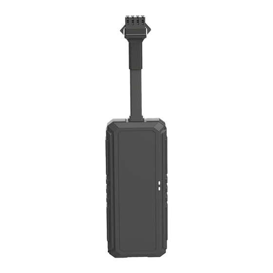
Page 4: Product Structure Description
Product structure description 4. Product parameter Specification content Specification Size 87(L)*35.5(W)*11(H)mm Weight Built-in battery 70mAH GSM module 850/900/1800/1900Mhz Chipsets ASR1603S/LAN/5311 Working temperature -20°C to +60°C Storage temperature -20°C to +70°C 32MB+32MB Frequency band LTE: B1/2/3/5/7/8/12/17/20/34/38/39/40/41 Phase error RMSPE<5, PPE<20... -
Page 5: Installation Instruction
Maximum output 22.5dBm Receiving sensitivity -102dBm Maximum frequency error ±0.1ppm Cold start: -145dBm Hot start: -156 dBm Sensitivity Warm start: -145 dBm Navigation: -160 dBm Tracking: -162 dBm positioning accuracy <1m First position time Cold start: 30 seconds on average GPS antenna Internal 25*25*4mm LED indicator... - Page 6 Second step: Insert the SIM card (the device must be cleaned before the SIM card is installed or removed) As shown in the picture below. ·Slowly lift the lid from the buckle ·OPEN the SIM card in the “OPEN” direction and put the SIM card in the correct direction.
- Page 7 2. Wiring diagram (Four-wire)
- Page 8 3. Power line and control interface The standard power supply of this equipment is 9v-36vdc, please choose the power line provided by the original factory, the red line is the positive pole of the power supply, and the black line is the negative pole of the power supply. When installing the power negative pole, please choose to ground or tie up the iron separately, do not connect with other ground wires.
- Page 9 4. Relay installation Cut off oil/engine Relay wiring method The terminals 86 and 85 are connected to the positive pole (+12V/+24V) of automobile/electric vehicle power supply and the control line of equipment relay respectively. Cut the positive connection wire of the oil pump/circuit, and connect the positive end of the oil pump to 87a end of the relay normally closed (87 end of the relay normally open), and connect the other end to 30 end of the relay, as shown in the picture: Note: be sure to pay attention to whether the locomotive battery voltage is...
- Page 10 The recommended installation location is as follows: Notice: 1. The product shall be installed face up to the sky. 2. If the windshield glass is pasted with metal heat insulation layer or heating layer, the satellite signal intensity will be reduced to receive, which may make it difficult for the satellite to locate.
-
Page 11: Product Basic Functions
Disconnect the external power supply and turn the backup battery switch to OFF position, then the terminal will shut down. After shutdown, the power indicator will go out and stop charging the internal battery. Note: before loading or unloading the SIM card, be sure to disconnect the external power supply and set the standby battery switch to OFF position! 6. -
Page 12: Led Light Working Instruction
7. LED light working instruction ·Status of satellite positioning signals... -
Page 13: Precautions
8. Precaution 1. Please pay attention to waterproof electronic products. 2. Please insert the SIM card before installation and make sure that the SIM card is not set with a password, otherwise the device will not work normally. 3. The USB port on the terminal device is dedicated for factory testing. It is not a charging port for the device and should not be used for charging or other purposes. -
Page 14: After-Sales Service
13. Do not connect the uninterruptible power supply without authorization, otherwise it may cause the car or the product to malfunction. For installation matters, please be sure to consult a professional. 14. Please do not subject the product to strong impact or vibration, so as to avoid damage to the product, resulting in malfunction or inoperability.
Need help?
Do you have a question about the 4G05NO and is the answer not in the manual?
Questions and answers