Advertisement
Quick Links
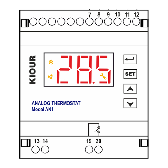
ANALOG THERMOSTAT Model ΑN1 V4
ATTENTION
Read carefully these instructions before installing and using this device and keep them for future reference. Attention to installation and electrical wiring. Use this device
only as described in this document and never use itself as a security device. The device must be disposed of in accordance with local standards for the collection of
electrical and electronic equipment.
DESCRIPTION
The analog thermostat AN1 Version 4 has the following technical characteristics:
1. One input, either for NTC temperature sensor of scale -50 ÷ +110 °C or PTC scale -50. ÷ +150 °C, and an input for signal 4-20mA, where the adjustment is made
through parameters. It analyzes 4-20 mA from 0 - 1000 units. This scale is defined by the parameter r nA, where if for example: r nA = 30, the scale of 4-20 mA will be
0 - 30.0 units (so 0 units = 4mA and 30.0 units = 20mA).
2. Output for 0-10 Volt signal. The signal settings are made through the parameters of the table below.
3. One relay controlled based on SET POINT and the corresponding differentials for cooling and heating, parameters diC and diH.
4. Power supply +12 Volt for transmitter
5. AS2 parameter. By parameter value:
AS2=1 the analog output works with the cooling set point SCo.
AS2=2 works with the heating set point SH1.
AS2=3 works with both set points, while the relay works only in the cooling area.
AS2=4 adjusts the analog voltage that drives the inverter / FAN so that the signal read by the differential pressostat is equal to SET POINT Sco.
The input to terminal blocks 7-11 works and when the contact is open the display shows OFF and the signal is reset.
AS2=5 adjusts the 0-10 Volts of the analog output based on the temperature from the temperature sensor and SET POINT SCo. And he tries to bears the measured
temperature equal to the value of SCo. By parameter IAO=0 the analog signal increases above the value of SCo and by parameter IAO=1 the analog signal is
reduced above the value of SCo. The input to terminal blocks 7-11 works as in option 4.
INDICATIONS AND BUTTONS FUNCTION
For more indications regarding the alarms please see the alarm's table at page 2.
INDUSTRIAL FACTORY SETTINGS
1.
Press
to display SCo. By pressing
2.
Press
to display its value and press
3.
Press
again to exit the parameter menu, 'YES' is displayed on the screen. All appropriate factory settings are now stored in the device.
4.
PROGRAMMING A PARAMETER
ATTENTION: to gain full access to the parameter's menu, the 3
1.
Press
to enter the parameter menu.
2.
Choose the parameter you want to adjust by pressing
3.
Press
or
to change its value and then press
4.
Press
to exit the parameter menu.
TECHNICAL SPECIFICATIONS
Power supply: 230VAC 50/60Hz / Maximum power consumption: 3W
It is recommended to use a power supply safety switch: fuse 0,5A (not included)
Temperature sensor PTC 1Κ 25
C with metal tube, temperature range -50÷+150°C (-58÷+302°F) or (NTC 10K 1% 25°C ΙΡ68 with temperature range -50÷+110°C
o
(-58÷+230°F) not included) / Accuracy: ±0.5°C
One input
4-20 mA
/ Relay
16A res. normally open contact / Serial input
Connections cable cross section
2.5 mm² for the relay /
Connections with terminal blocks 18A using cable with
The device is mounted on an Ω rail / IP20 protection
Operating temperature: -15÷+55°C / Storage temperature: -20÷+80°C
Firmware V4.0.0
SERIAL INPUT
AN1 can connect to the key programmer or to the data logger Mini Logger or to the KIOUR CAMIN network or to any modbus network.
Key programmer: controller's parameter values can be saved or retrieved from the programming key. Plug in the programming key to the controller and press at the same
time [SET]+[
]. The device connects to the key and the message "Eo" is displayed. By pressing [
"ro" = read O.K. or "rF" = read Fail is displayed. By pressing [
Indications
Relay 1 ON
alarm ΟΝ
malfunction ON
the parameter Cod is displayed.
to enter the value 31. Press
rd
parameter Cod must be adjusted to 22 (see parameter table next page)
or
and press
to store the new
cable cross section
from 0.25 to 1.0 mm² for the sensor
cable cross section
up to 2.5 mm². / It is recommended using a torque wrench with maximum torque 0.4Nm
] the device uploads the parameters to the key and the message "Yo" = Write O.K. or "YF" = Write Fail is
Keyboard
enter/exit the parameter's menu
display the parameter's value
SET
enter parameter's value
to store the value to parameter
Cod.
to display its value.
value.
] the device downloads the parameters from the key and the message
KIOUR
Firmware V4.0.0
up arrow
down arrow
1
Advertisement

Related Manuals for KIOUR AN1 V4


Summary of Contents for KIOUR AN1 V4
- Page 1 SERIAL INPUT AN1 can connect to the key programmer or to the data logger Mini Logger or to the KIOUR CAMIN network or to any modbus network. Key programmer: controller’s parameter values can be saved or retrieved from the programming key. Plug in the programming key to the controller and press at the same time [SET]+[ ].
- Page 2 In case of failure (rF or YF) reenter the key to the serial input and repeat the procedure from the beginning. The key can connect to all KIOUR devices. If you try to read the parameters of a different device, message “rF” is displayed. At any time, we can perform the aforesaid operation. After 10sec the key is disconnected.
- Page 3 The device is under two year’s guarantee. The guarantee is valid only if the manual instructions have been applied. The control and service of the device must be done by an authorized technician. The guarantee covers only the replacement or the service of the device. KIOUR PC implements a Quality Management System according to EN ISO 9001:2015 Standard with registration number 01013192.
Need help?
Do you have a question about the AN1 V4 and is the answer not in the manual?
Questions and answers