Advertisement
Quick Links
This instruction is valid for all standard low pressure pumps:
LPD, ACD, ACE, LPE, ACG/UCG, ACF/UCF, LPQ and ABQ
Contents
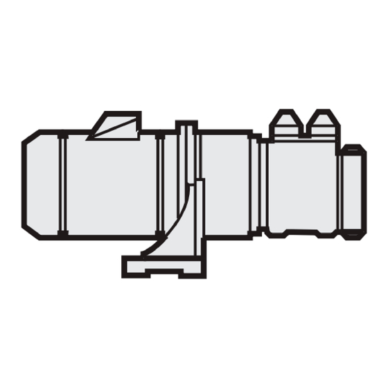
Pump identification
Installation
Start-up
Trouble shooting
Before commencing any work, read this instruction carefully! Failure to comply
with these instructions may cause damage and personal injury!
Page
2
3
8
10
Advertisement

Related Manuals for IMO LPD Series


Summary of Contents for IMO LPD Series
- Page 1 This instruction is valid for all standard low pressure pumps: LPD, ACD, ACE, LPE, ACG/UCG, ACF/UCF, LPQ and ABQ Contents Page Pump identification Installation Start-up Trouble shooting Before commencing any work, read this instruction carefully! Failure to comply with these instructions may cause damage and personal injury!
- Page 2 (3) E = Without valve A327 Pump with Tuning® G = Valve with external return A328 Pump with Tuning® O = Valve with internal return for reduced pressure A385 A101 + A327 range P = Valve with internal return for total pressure range www.imo.se...
- Page 3 Design limitations and technical data for each pump are found in the Product description. Installation of IMO AB low pressure pumps does not require special skills. However, these instructions presume that the work is carried out by experienced fi ers.
- Page 4 For other types of couplings, please refer to respective maker’s manual. Fig. 3 Alignment of the IMO AB standard coupling When fi ing the sha coupling, do not use a hammer or similar as this may damage the Outer diameter Distance between Outer diameter Distance between ball bearing and sha seal.
- Page 5 (2-3 mm recom mended) has to be installed. The deaeration pipe should be connected to the outlet pipe’s highest point. This must also be installed when the pump is used as an stand-by pump. Fig. 8 Deaeration www.imo.se...
- Page 6 In such installations the suction pipe should be arranged so it forms a liquid trap together with the pump, keeping the pump half filled with liquid. See fig. 11. Fig. 11 Liquid trap www.imo.se...
- Page 7 All systems with screw pumps must be equipped with a pressure relief valve installed immediately adjacent to the pump. In the standard versions of IMO AB low pressure pumps, this pressure relief valve is an integral part of the pump to protect the system against excess pressure.
- Page 8 The arrow is placed on different spots depending on the pump series. ATTENTION Don’t mix up with arrow for inlet and outlet! Fig. 17 Direction of rotation www.imo.se...
- Page 9 1. Before starting the se ing check that both se ing screws (8 mm socket head cap screw on the discharge side) are closed. 2. Turn the lower screw until the noise level obtains a minimum.(If turned too much the noise will increase again). www.imo.se...
- Page 10 See the chapter on Noise and significant amount of com - Vibration. ( Page 11). pressible gas, such as free air. (This would usually cause noise). A too small pump has been Contact your IMO AB chosen. representa tive. www.imo.se...
- Page 11 Free air in the liquid or gas For pumps with Tuning: cavitation. Adjust the Tuning. If this does not help or for pumps without Tuning: Contact your IMO representative or IMO service dept. Faulty electrical supply. Check all three phases of the supply.
Need help?
Do you have a question about the LPD Series and is the answer not in the manual?
Questions and answers