Table of Contents

Related Manuals for IMO OptiLine LPE4


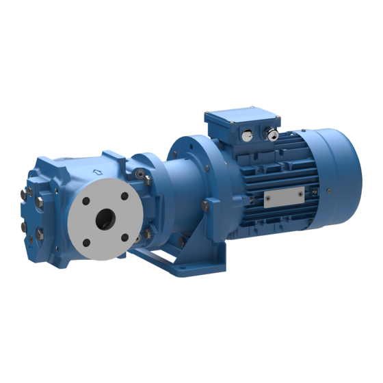
Summary of Contents for IMO OptiLine LPE4
-
Page 1: Table Of Contents
Screw pumps OptiLine LPE4 Original Operating Manual Contents Page Introduction Safety Installation Start-up Trouble shooting Maintenance and Service Service intervals List of components Exploded View/Ordering code Dismantling and reassembling the pump Dismantling Reassembly Before commencing any work, read this instruction carefully! Failure to comply with... -
Page 2: Introduction
• Only operate the pump if it is in perfect technical condition and only use it as intended, remaining aware of safety and risks, and adhere to the instructions in this manual. • Keep this manual and all other applicable documents complete, legible and accessible to personnel at all times. www.imo.se... - Page 3 • Reinstall the safety equipment on the pump as required by regulations after any work on the pump. • With an implanted pacemaker: – Stay at least 1 meter away from the pump with magnetic coupling or parts of the magnetic coupling. – Do not work with or on the magnetic parts. www.imo.se...
- Page 4 The magnetic field of the magnetic coupling can destroy products that are sensitive to magnets. These include: • Pacemakers • Plastic identity cards with magnetic strips • Credit and check cards • Electric, electronic and precision mechanical devices (such as mechanical and digital clocks, pocket calculators, hard disks) www.imo.se...
-
Page 5: Installation
Installation Design limitations and technical data for each pump are found in the Product description. Installation of IMO AB low pressure pumps does not require special skills. However, these instructions presume that the work is carried out by experienced fitters! - Page 6 Fig. 6 Deaeration When handling liquids that may harm skin use gloves and/or protective clothing When handling liquids shich may involve fire hazards appropriate precautions to avoid danger are to be taken. Fig. 7 Liquid trap www.imo.se...
- Page 7 All systems with screw pumps must be equipped with a pressure relief valve installed immediately adjacent to the pump. In the standard versions of IMO LPE Optiline pumps, this pressure relief valve is an integral part of the pump to protect the system against excess pressure.
-
Page 8: Startup
Air in the pumped fluid It is forbidden to use the LPE Optiline pump with fluids Fig. 13 Differential Pressure that contains more than 0,2% of air due to the risk of ignition during an eventual overheating of the pump. www.imo.se... -
Page 9: Trouble Shooting
(This would usually line (strainers, valves etc.). cause noise). - The pumped liquid contains a Go thru the system and determine if significant amount of compressible there are any leaks. gas, such as free air. (This would usually cause noise). www.imo.se... - Page 10 (This would usually cause noise). - A too small pump has been chosen. Contact your IMO AB representative. Pressure too high - The pressure relief valve is set too Readjust the pressure relief valve.
- Page 11 www.imo.se...
-
Page 12: Maintenance And Service
Introduction A screw pump from IMO is a quality product that is designed for a long problem free operation in tough environ- ments. As all other mechanical products they do however requires a certain grade of maintenance and service in order to guarantee a faultless and economic favourable operation. -
Page 13: Service Intervals
IMO does NOT take any responsibili- ties for damages caused by improper use or damages Oil leakage may make the floor slippery related to this. -
Page 14: List Of Components
Compl. Valve (605) O-ring (608) Valve spindle (608A) Tension pin 6120 Set screw (613) Tension pin (614) Valve piston (615) Valve spring Stud bolt 701A Washer 701B Screw 702A Washer Screw 703A Washer 703B Nuts Drive hub 998B Screw www.imo.se... -
Page 15: Exploded View/Ordering Code
Ball bearing Repair after break down G098 Magnetic xKxx 193370 193370 coupling " xLxx 193371 193371 193371 " xMxx 193372 193372 " xNxx 193373 Ball bearing 173765 173765 173591 Flange kit 193998 193999 194000 Flange gasket 193997 193996 158626 www.imo.se... -
Page 16: Dismantling And Reassembling The Pump
E = Screw driver 703B IEC B = Spanner 16 mm F = Plier 80-90 C = Plastic mallet G = Oil can 100-132 D = Allen keys (3 mm & 5 mm) 998B IEC 100-132 Sectional View Loctite 222 www.imo.se... -
Page 17: Dismantling
• Pull out the sealing can 005B coupling. Beware of the magnetic force! • Remove the o-ring 007B 005A • Remove the circlip 005A with a suitable plier. • Remove the inner magnetic rotor by means of a suitable puller. www.imo.se... - Page 18 • Remove the support washer 124A from the main rotor 1020. • Remove the ball bearing 122 from the main • Pull out the idlers 202 from the pump body. rotor 1020 with a suitable puller www.imo.se...
- Page 19 • Remove the relief valve and replace the o-ring 605. • Remove bolts 702 and pull out the motor from • Reassembly relief valve. the connection frame. • Unscrew the bolts 006A and remove the • Release the screw 998B. magnet 005D from the drive hub 998. www.imo.se...
-
Page 20: Reassembly
• Tight the screw 998B firmly. • Mount the magnet 005D onto the drive hub • Mount the electrical motor back into the con- 998 by tightening the bolts 006A. necting frame and tight the bolts 702. www.imo.se... - Page 21 • Mount the inner magnet 005C onto the shaft • Mount the circlip 005A with a plier. by using a stud bolt M6 with a suitable washer and nut, press the inner magnet into its final position by using hand force or distance ring. www.imo.se...
- Page 22 • Tight the bolts 453 with the correct torque that can be found in Tightening Torque table. • Mount the pump into the connection frame in a • Tighten the bolts 701 according to Tightening straight line. Torque table. www.imo.se...
- Page 23 www.imo.se...
- Page 24 Adress: IMO AB Solna Torg 19, 2tr 171 45 Solna, Sweden www.imo.se...
Need help?
Do you have a question about the OptiLine LPE4 and is the answer not in the manual?
Questions and answers