Table of Contents

Subscribe to Our Youtube Channel
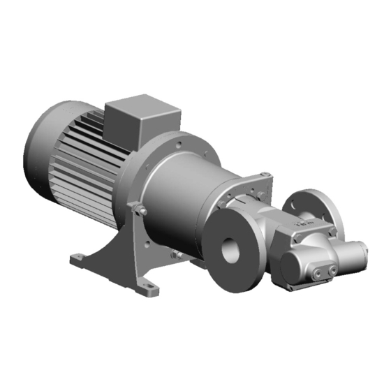
Related Manuals for IMO OptiLine ACG8


Summary of Contents for IMO OptiLine ACG8
-
Page 1: Table Of Contents
Screw pumps OptiLine ACG8 Original Operating Manual Contents Page Introduction Safety Installation Start-up Trouble shooting Maintenance and Service List of components Exploded View/Ordering code Service intervals Dismantling and reassembling the pump Dismantling Reassembly Before commencing any work, read this instruction carefully! Failure to comply with... -
Page 2: Introduction
• Only operate the pump if it is in perfect technical condition and only use it as intended, remaining aware of safety and risks, and adhere to the instructions in this manual. • Keep this manual and all other applicable documents complete, legible and accessible to personnel at all times. www.imo.se... - Page 3 • Reinstall the safety equipment on the pump as required by regulations after any work on the pump. • With an implanted pacemaker: – Stay at least 1 meter away from the pump with magnetic coupling or parts of the magnetic coupling. – Do not work with or on the magnetic parts. www.imo.se...
- Page 4 The magnetic field of the magnetic coupling can destroy products that are sensitive to magnets. These include: • Pacemakers • Plastic identity cards with magnetic strips • Credit and check cards • Electric, electronic and precision mechanical devices (such as mechanical and digital clocks, pocket calculators, hard disks) www.imo.se...
-
Page 5: Installation
Installation Design limitations and technical data for each pump are found in the Product description. Installation of IMO AB low pressure pumps does not require special skills. However, these instructions presume that the work is carried out by experienced fitters! - Page 6 Fig. 6 Deaeration When handling liquids that may harm skin use gloves and/or protective clothing When handling liquids shich may involve fire hazards appropriate precautions to avoid danger are to be taken. Fig. 7 Liquid trap www.imo.se...
- Page 7 All systems with screw pumps must be equipped with a pressure relief valve installed immediately adjacent to the pump. In the standard versions of IMO ACG Optiline pumps, this pressure relief valve is an integral part of the pump to protect the system against excess pressure.
-
Page 8: Startup
Air in the pumped fluid Fig. 13 Differential Pressure It is forbidden to use the ACG Optiline pump with fluids that contains more than 0,2% of air due to the risk of ignition during an eventual overheating of the pump. www.imo.se... -
Page 9: Trouble Shooting
- The pumped liquid contains a signif- See the chapter on Noise and Vibra- icant amount of compressible gas, tion. (Page 11). such as free air. (This would usually cause noise). - A too small pump has been chosen. Contact your IMO AB representative. www.imo.se... - Page 10 Check the suction line for air leakage. malfunction is - Free air in the liquid or gas cavita- For pumps with Tuning: noticed tion. Contact your IMO representative or IMO service department. - Faulty electrical supply. Check all three phases of the supply. www.imo.se...
-
Page 11: Maintenance And Service
Introduction A screw pump from IMO is a quality product that is designed for a long problem free operation in tough environ- ments. As all other mechanical products they do however requires a certain grade of maintenance and service in order to guarantee a faultless and economic favourable operation. -
Page 12: List Of Components
Sealing washer Valve housing 5010 Front cover Plug Gasket Retaining ring Gasket Valve cover Sealing washer O-ring Valve spindle 608A Retaining ring Regulating nut Valve piston Valve spring Screw 701A Washer Screw 702A Washer Screw 703B Drive hub 998B Screw www.imo.se... -
Page 13: Exploded View/Ordering Code
L 193038 193038 193041 193044 the pump M 193039 193039 193042 193045 193131 Guide pins For dismantling Ball bearing 192855 192855 192827 192827 pump size 070 and assembly of Valve housing 191022 191025 191028 191031 the pump www.imo.se... -
Page 14: Service Intervals
In case of failure for system with elevated pling or its components are not to be allowed under any pressure, fluid jets may cause injury and/ circumstances. IMO does NOT take any responsibili- or damage. ties for damages caused by improper use or damages related to this. -
Page 15: Dismantling And Reassembling The Pump
G = Circlip pliers C = Plastic mallet H = Guide Pins (for ordering code, see table page 5) D = Allen keys various sizes J = Oil can E = Mounting Sleeve for ball bearing (sizes - see table) Sectional View www.imo.se... -
Page 16: Dismantling
• The use of a strap or similar devices on the electrical motor in order to stabilize and secure the package from the magnetic force is recom- mended. www.imo.se... - Page 17 • Remove the inner magnetic rotor with a suita- ble three arm puller • Pull out the sealing can 005B with its o-ring 007B • Remove the circlip 005A with a suitable plier. • Remove the key 113 from the pump shaft. www.imo.se...
- Page 18 • Pull out the power rotor 1020 with its ball bear- • Unscrew the bolts 451 from the front cover ing 122 by hand force from the pump body. 5010 • Separate the front cover 5010 with its gasket 506 from the pump house 401. www.imo.se...
- Page 19 • Unscrew the 4 bolts 702 with a suitable span- means of a suitable open spanner and pull it ner and separate the connecting frame 003 out from the rear cover 480 together with its from the electrical motor 002 seal ring 602. www.imo.se...
- Page 20 998 • Measure the distance on the shaft coupling and • Use a three arm legged puller and remove the note the value so that it can used during the coupling 998 from the electrical motor. assembly later on. www.imo.se...
-
Page 21: Reassembly
NOTE: Do not use a hammer as this can Dam- age the shaft! • Measure the distance in order to get the same • Tight the looking bolt 998B with a suitable hex- as before the coupling was removed. agon key www.imo.se... - Page 22 124 with a suitable plier on the power rotor cal motor 002 by means of tightening the bolts 1020. 702 according to the tightening torque table on page 17 in this manual. • Mount the key 113 on the power rotor 1020. www.imo.se...
- Page 23 Note: do not forget to lubricate the rotor washer, push it into its final position by means of prior to the mounting. a suitable socket. NOTE: DO NOT USE A HAMMER AS THIS CAN DAMAGE THE PARTS! www.imo.se...
- Page 24 • Mount the sealing can 005B with its o-ring pump body 007B onto the pump and tight the bolts 007A according to the tightening torque table on • Make sure that the lubrication slots are pointing page 17 in this manual. backwards www.imo.se...
- Page 25 • Tight the nut accordingly with a suitable span- ner. • Attach 4 bolts in the pumps front cover in order to avoid a to rapid mounting due the magnetic forces that will take place when the pump pack- age is joined. www.imo.se...
- Page 26 FRAME AND THE PUMP AS AN ACCI- HANDS BETWEEN THE CONNECTING DENTAL SLIP DOWNWARDS EASILY CAN FRAME AND THE PUMP AS AN ACCI- CRUSH A HAND OR EVEN CUT A FINGER. DENTAL SLIP DOWNWARDS EASILY CAN CRUSH A HAND OR EVEN CUT A FINGER. www.imo.se...
- Page 27 Tightening torque (Nm) Size Pos.No 006A 007A 702/IEC 100-132 702/IEC 160-225 703B/IEC 100-132 703B/IEC 160-225 998B • Tight the bolts 701 with its washers 701A with a suitable spanner according to the torque tightening table on this page. www.imo.se...
- Page 28 Adress: IMO AB Solna Torg 19, 2tr 171 45 Solna, Sweden www.imo.se...
Need help?
Do you have a question about the OptiLine ACG8 and is the answer not in the manual?
Questions and answers