Table of Contents
Advertisement
Original Operating Manual
Contents
Before commencing any work, read this instruction carefully! Failure to comply with
!
these instructions may cause damage and personal injury!
Tel: +44 (0) 1773 302 660 | Email: sales@northridgepumps.com | Website: www.northridgepumps.com
X-Cel House, Chrysalis Way, Langley Bridge, Eastwood, Nottinghamshire NG16 3RY
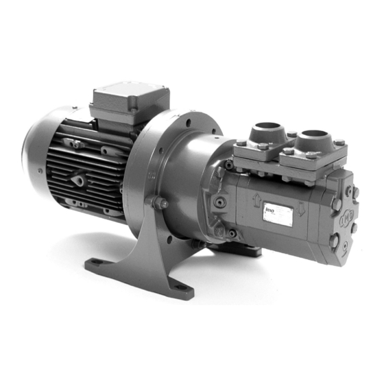
Screw pumps
ACE3
Page
2
2
4
5
10
12
14
14
15
16
17
18
19
23
Advertisement
Table of Contents

Subscribe to Our Youtube Channel
Related Manuals for IMO ACE3 Series


Summary of Contents for IMO ACE3 Series
-
Page 1: Table Of Contents
Screw pumps ACE3 Original Operating Manual Contents Page Introduction Safety Pump identification Installation Start-up Trouble shooting Maintenance and Service List of components Exploded View Ordering code/Service intervals Sectional view Useful tools/Shaft seal-assembly drawing Dismantling/Reassembly Pressure relief valve Before commencing any work, read this instruction carefully! Failure to comply with these instructions may cause damage and personal injury! X-Cel House, Chrysalis Way, Langley Bridge, Eastwood, Nottinghamshire NG16 3RY Tel: +44 (0) 1773 302 660 | Email: sales@northridgepumps.com | Website: www.northridgepumps.com... -
Page 2: Introduction
Introduction Other applicable documents Document Purpose Order data sheet Technical specifications, conditions of operation Technical description Technical specifications, operating limits Supplier documentation Technical documentation for parts supplied by subcontractors, e.g. drive system, coupling or auxiliary operating system. Spare parts list Ordering spare parts Declaration of conformity Conformity with standards,... - Page 3 • Keep this manual and all other applicable documents complete, legible and accessible to personnel at all times. • Refrain from any procedures and actions that would pose a risk to personnel or third parties. • In the event of any safety-relevant malfunctions, shut down the pump immediately and have the malfunc- tion corrected by the personnel responsible.
-
Page 4: Pump Identification
Specific hazards Hazardous pumped liquids • Observe the safety regulations for handling hazardous substances (e.g. hot, flammable, poisonous or po- tentially harmful) when handling hazardous pumped liquids. • Use personal protective equipment when carrying out any work on the pump. •... -
Page 5: Installation
BEFORE COMMENCING ANY WORK, READ THIS INSTRUCTION CAREFULLY! Design limitations and technical data for each pump are found in the Product description. Installation of IMO AB low pressure pumps does not require special skills. However, these instructions presume that the work is carried out by experienced fitters. - Page 6 For other types of couplings, please refer to respective maker’s manual. Fig. 3 Alignment of the IMO AB standard coupling When fitting the shaft coupling, do not use a hammer or similar as this may Outer diameter Distance between Outer diameter Distance between damage the ball bearing and shaft seal.
- Page 7 For direct driven pumps the alignment between Measures shall be provided to avoid pump and motor shafts must be kept within the accidental contact with the rotating shaft following limits: coupling. Any installed coupling guard shall permit easy access to the pump Max run-out Max angular shaft for maintenance and inspection of...
- Page 8 Strainer The pump has to be protected from foreign matter, such as weld slag, pipe scale, etc., that could enter the pump via the suction line. If the cleanliness of the system cannot be guaranteed, a strainer must be installed in the inlet pipe near the pump. For practical reasons a suction strainer with 0.6 mm mesh openings is recommended: The size of the strainer should be selected so that...
- Page 9 All systems with screw pumps should be equipped with a pressure relief valve installed immediately adjacent to the pump. In the standard versions of IMO AB low pressure Fig. 12 Gauges pumps, this pressure relief valve is an integral part of the pump to protect the pump against excess pressure.
-
Page 10: Start-Up
Start-up Before starting After installation and whenever it can be assumed that the pump has been emptied, the pump must be thoroughly filled with liquid. See fig 15. For ACE Generation 3, LPE Generation 3, ACG Generation 7 and ACF Generation 4 delivered after 1997, ACF Generation 5 and LPQ the pumps have been fitted with deaeration plugs making venting of the shaft seal compartment easy before start-up. - Page 11 Starting Setting of tuning of the LPQ: 1. Before starting the setting check that both setting Check that all valves necessary for the operation screws (8 mm socket head cap screw on the are fully opened in both discharge and suction lines. discharge side) are closed.
-
Page 12: Trouble Shooting
- -pressible gas, such as free air. (This would usually cause noise). Contact your IMO AB A too small pump has been representa tive. chosen. X-Cel House, Chrysalis Way, Langley Bridge, Eastwood, Nottinghamshire NG16 3RY... - Page 13 Free air in the liquid or gas For pumps with Tuning: cavitation. Adjust the Tuning. If this does not help or for pumps without Tuning: Contact your IMO representative or IMO service dept. Faulty electrical supply. Check all three phases of the supply.
-
Page 14: Maintenance And Service
Maintenance and Service List of components Valid for all pumps in sizes: ACE 025/032/038 Rotor diameter and Generation: D3/K3/L3/N3 With version codes: Also valid for pump options: A101 The version code is composed of the letters in the 4 columns. Example of pump designations std: ACE 025L3 NTBP;... -
Page 15: Exploded View
Exploded view 1020 462A xVxx xTxx 537A (608A) 463 463A (605) (608) 537A (6120) (613) 557A (615) (614) Removed from August xTxx 2011 Fig. 1 When handling liquids which may involve All work carried out on the pump has to be fire hazards appropriate precautions to performed in such a manner that risks for avoid danger are to be taken. -
Page 16: Ordering Code/Service Intervals
190525 190714 190522 Joint kit-xTxx 190524 190713 190523 Ordering example: G070 Valve element 189873 189873 189873 For IMO-pump ACE 032N3 NVBP, Secondary seal xTxx 190469 190469 190468 serial number 456789: Shaft seal pos G050 p/n 194030 Valve element pos G070 p/n 189873... -
Page 17: Sectional View
Sectional view 125 (xTxx) Removed from August 2011 C - C E - E 463A 537A Fig. 2 X-Cel House, Chrysalis Way, Langley Bridge, Eastwood, Nottinghamshire NG16 3RY Tel: +44 (0) 1773 302 660 | Email: sales@northridgepumps.com | Website: www.northridgepumps.com... -
Page 18: Useful Tools/Shaft Seal-Assembly Drawing
16 mm Puller Tool 2 Tool 1 Sliding calliper For dimension and material, please contact IMO AB Service. Fig. 3 Shaft seal - assembly drawing Shaft seal G050 (509) Seat slot Version code xVxx S1 Seat Front S2 O-ring... -
Page 19: Dismantling/Reassembly
Dismantling • Turn the electricity OFF. • Close the valves. • Remove the pump from the system. ATTENTION Use appropriate vessels to collect oil • Note the position of the shaft coupling. spillage when removing and opening the pump. • Release the stop screw. - Page 20 xTxx 1020 • Separate the front cover 501 and the power rotor 1020. • Remove the secondary seal 125 with a suitable screw driver. Fig. 11 Fig. 12 xVxx xTxx xQxx xVxx • Place the front cover 501 on a pair of wood- en pieces.
- Page 21 Reassembly • Un-pack a new shaft seal 509. • Check that the O-ring S6 is in place. xVxx xTxx • Lubricate the idler rotors 202 S4 S7 and fit them into the pump body 401. Lubrication groves turning downwards. Fig. 17 Fig.
- Page 22 xVxx xTxx Tool 1 Tool 1 • Fit the spring unit S7 in place. • Fit the retainer S3 Note the position for the Seat in place. Note the slots and lugs. position for the (See fig 4.) retainer lugs and cover slots.
-
Page 23: Pressure Relief Valve
Reassemble the parts in reverse order. Be care- ful to tighten the screws 453 crosswise. • Readjust the valve pressure according to the ”Installation and Start-up Instruction for IMO Low Fig. 29 pressure pumps”. X-Cel House, Chrysalis Way, Langley Bridge, Eastwood, Nottinghamshire NG16 3RY...
Need help?
Do you have a question about the ACE3 Series and is the answer not in the manual?
Questions and answers